EP0066262A1 - Procédé de fabrication d'une ferrure d'extrémité d'isolateur électrique - Google Patents
Procédé de fabrication d'une ferrure d'extrémité d'isolateur électrique Download PDFInfo
- Publication number
- EP0066262A1 EP0066262A1 EP82104642A EP82104642A EP0066262A1 EP 0066262 A1 EP0066262 A1 EP 0066262A1 EP 82104642 A EP82104642 A EP 82104642A EP 82104642 A EP82104642 A EP 82104642A EP 0066262 A1 EP0066262 A1 EP 0066262A1
- Authority
- EP
- European Patent Office
- Prior art keywords
- fitting
- complementary parts
- complementary
- hoop
- parts
- Prior art date
- Legal status (The legal status is an assumption and is not a legal conclusion. Google has not performed a legal analysis and makes no representation as to the accuracy of the status listed.)
- Withdrawn
Links
- 229910052751 metal Inorganic materials 0.000 title claims description 9
- 239000002184 metal Substances 0.000 title claims description 9
- 238000004519 manufacturing process Methods 0.000 title claims description 5
- 239000000615 nonconductor Substances 0.000 title claims description 4
- 230000000295 complement effect Effects 0.000 claims abstract description 17
- 238000000034 method Methods 0.000 claims description 17
- 238000003466 welding Methods 0.000 claims description 8
- 239000000463 material Substances 0.000 claims description 6
- 238000004873 anchoring Methods 0.000 claims description 5
- 238000005266 casting Methods 0.000 claims description 5
- 239000002131 composite material Substances 0.000 claims description 3
- 238000002788 crimping Methods 0.000 claims description 2
- 238000000465 moulding Methods 0.000 abstract description 2
- 229910000831 Steel Inorganic materials 0.000 description 3
- 239000010959 steel Substances 0.000 description 3
- 229910000838 Al alloy Inorganic materials 0.000 description 2
- 229910001018 Cast iron Inorganic materials 0.000 description 2
- 239000012212 insulator Substances 0.000 description 2
- 238000005304 joining Methods 0.000 description 2
- 229910000906 Bronze Inorganic materials 0.000 description 1
- RYGMFSIKBFXOCR-UHFFFAOYSA-N Copper Chemical compound [Cu] RYGMFSIKBFXOCR-UHFFFAOYSA-N 0.000 description 1
- 229910000881 Cu alloy Inorganic materials 0.000 description 1
- 229910045601 alloy Inorganic materials 0.000 description 1
- 239000000956 alloy Substances 0.000 description 1
- 229910052782 aluminium Inorganic materials 0.000 description 1
- XAGFODPZIPBFFR-UHFFFAOYSA-N aluminium Chemical compound [Al] XAGFODPZIPBFFR-UHFFFAOYSA-N 0.000 description 1
- 239000010974 bronze Substances 0.000 description 1
- 239000010949 copper Substances 0.000 description 1
- 229910052802 copper Inorganic materials 0.000 description 1
- KUNSUQLRTQLHQQ-UHFFFAOYSA-N copper tin Chemical compound [Cu].[Sn] KUNSUQLRTQLHQQ-UHFFFAOYSA-N 0.000 description 1
- 238000007872 degassing Methods 0.000 description 1
- 230000000694 effects Effects 0.000 description 1
- 230000009969 flowable effect Effects 0.000 description 1
- 239000003365 glass fiber Substances 0.000 description 1
- 230000006698 induction Effects 0.000 description 1
- 239000004576 sand Substances 0.000 description 1
- 238000007789 sealing Methods 0.000 description 1
Images

Classifications
-
- H—ELECTRICITY
- H01—ELECTRIC ELEMENTS
- H01B—CABLES; CONDUCTORS; INSULATORS; SELECTION OF MATERIALS FOR THEIR CONDUCTIVE, INSULATING OR DIELECTRIC PROPERTIES
- H01B17/00—Insulators or insulating bodies characterised by their form
- H01B17/38—Fittings, e.g. caps; Fastenings therefor
- H01B17/40—Cementless fittings
Definitions
- the present invention relates to a method for manufacturing an electrical insulator fitting and relates to fittings intended, in particular but not exclusively, to equip the ends of composite insulators.
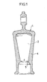
- Such a fitting schematically has a cavity open on one side to receive the end of a rod made of agglomerated glass fibers which is immobilized by sealing or shrinking. It is generally made of cast iron, steel, aluminum alloy or copper alloy and is produced by casting.
- FIG. 1 schematically illustrates in section a fitting 1 of this kind and its cavity 2.
- a side wall 4 is generally provided, forming an internal narrowing 5 of diameter d.
- the only usable process is casting on a core of sand.
- This process has many drawbacks.
- the sand cores leave a rough surface state; in addition they are slightly porous and the degassing which appears at high temperature, and which cannot be released since the cavity is blind, further deteriorates the surface condition.
- this surface condition must have a quality which allows relative sliding of the anchoring material on the interior surface of the cavity of the fitting in order to obtain a "self-locking" action by a wedging effect. A high specific resistance is thus obtained from the anchoring of the rod thus produced.
- the object of the present invention is to propose a method of manufacturing a fitting making it possible to obtain a satisfactory internal surface condition.
- the present invention relates to a method of manufacturing an end fitting of a composite electrical insulator, fitting having an internal cavity with a predetermined surface state to receive the sealed end of an insulating rod; for this, two complementary parts are produced separately having said surface condition by a process chosen from casting on a metal core, or stamping, stamping, stamping of a sheet metal; then said complementary parts are joined to one another by an assembly process of the welding, crimping, riveting type, the joining connector being sufficiently fine so as not to alter said surface condition and to leave the possibility of sliding for " self-locking "explained above.
- the complementary parts can therefore be made of any flowable material, for example cast iron, steel, aluminum alloy or copper.
- the complementary parts can be identical, and their contact zone is then located in a plane of symmetry of the fitting.
- the contact faces may have more or less crenellated or wavy zones favoring their joining or mutual interlocking.
- a metal hoop at least around the portion of the fitting capable of undergoing the most mechanical stresses.
- This hoop is put in place by a process known per se. It can be welded to the fitting. Its material is chosen so as to have a coefficient of expansion compatible with that of the complementary parts of the fitting.
- Means may also be provided for consolidating the assembled zones, external to the complementary parts.
- the latter may include anchoring grooves for safety keys.
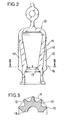
- FIGS. 2 and 3 show a half-fitting 10 according to the invention. This half-fitting was molded and its surface condition could be perfectly checked. After welding the facing faces 14 of the two half-fittings, the part of the fitting between its upper part and the throttle 15 is surrounded by a one-piece cylindrical hoop 11. The hooped part is capable of withstanding significant mechanical stresses.
- the hoop is put in place by a process known per se on ribs 12 molded with the wall of the half-fitting 10. These ribs each have a shoulder 16 which serves as a stop for the hoop 11. The latter can be welded locally at the wall of the fitting. We see in Figure 3 the polygonal shape taken by the hoop 11 after its shrinking.
- Figures 4 and 5 show another variant of half-fitting 20 according to the invention, which is not molded but made from a sheet of a deformable metal.
- the end 22 of the half-fitting 20 is pierced or cut at 21 after the latter has been formed.
- a hoop 23 is made around the most mechanically stressed zone 23 by casting in a mold of which a half-shell 24 can be seen in FIG. 4.
- the material of the hoop 23 is chosen from an appropriate alloy which causes pre-stress on the half-fittings when it cools, by shrinking.
- FIG. 5 shows a section of the two half-fittings 20 and 30 welded together and provided with their hoop 23.
- the weld zone has been identified and it will be noted that the half-fittings 20 and 30 are thicker at this zone.
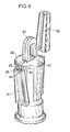
- FIG. 6 illustrates another embodiment without using a hoop.
- the two half-fittings 41 and 42 are welded according to a surface, the outer line 40 of which can be seen; in the vicinity of the weld, the conical walls of the half-fittings have angled edges 43 and 44 defining two housings for the edges 45 and 46 of a key 51.
- a second key 52 is provided to reinforce the opposite weld surface. The upper part of the keys can be optionally closed.
Landscapes
- Insulators (AREA)
- Connection Of Plates (AREA)
Applications Claiming Priority (2)
| Application Number | Priority Date | Filing Date | Title |
|---|---|---|---|
| FR8110772A FR2506998A1 (fr) | 1981-06-01 | 1981-06-01 | Procede de fabrication d'une ferrure d'extremite d'isolateur electrique |
| FR8110772 | 1981-06-01 |
Publications (1)
| Publication Number | Publication Date |
|---|---|
| EP0066262A1 true EP0066262A1 (fr) | 1982-12-08 |
Family
ID=9259043
Family Applications (1)
| Application Number | Title | Priority Date | Filing Date |
|---|---|---|---|
| EP82104642A Withdrawn EP0066262A1 (fr) | 1981-06-01 | 1982-05-27 | Procédé de fabrication d'une ferrure d'extrémité d'isolateur électrique |
Country Status (2)
| Country | Link |
|---|---|
| EP (1) | EP0066262A1 (enExample) |
| FR (1) | FR2506998A1 (enExample) |
Cited By (1)
| Publication number | Priority date | Publication date | Assignee | Title |
|---|---|---|---|---|
| WO2000011685A1 (de) * | 1998-08-18 | 2000-03-02 | Siemens Aktiengesellschaft | Vorrichtung zur verbindung eines ersten oberleitungsbauteils, das ein axiales abschlussteil aufweist, mit wenigstens einem zweiten oberleitungsbauteil |
Citations (3)
| Publication number | Priority date | Publication date | Assignee | Title |
|---|---|---|---|---|
| CH152055A (de) * | 1930-10-31 | 1932-01-15 | Matthey Charles | Isolator. |
| CH504085A (de) * | 1970-02-12 | 1971-02-28 | Dietz Alfred | Hängeisolator |
| GB1233310A (enExample) * | 1969-08-04 | 1971-05-26 |
-
1981
- 1981-06-01 FR FR8110772A patent/FR2506998A1/fr active Granted
-
1982
- 1982-05-27 EP EP82104642A patent/EP0066262A1/fr not_active Withdrawn
Patent Citations (3)
| Publication number | Priority date | Publication date | Assignee | Title |
|---|---|---|---|---|
| CH152055A (de) * | 1930-10-31 | 1932-01-15 | Matthey Charles | Isolator. |
| GB1233310A (enExample) * | 1969-08-04 | 1971-05-26 | ||
| CH504085A (de) * | 1970-02-12 | 1971-02-28 | Dietz Alfred | Hängeisolator |
Cited By (1)
| Publication number | Priority date | Publication date | Assignee | Title |
|---|---|---|---|---|
| WO2000011685A1 (de) * | 1998-08-18 | 2000-03-02 | Siemens Aktiengesellschaft | Vorrichtung zur verbindung eines ersten oberleitungsbauteils, das ein axiales abschlussteil aufweist, mit wenigstens einem zweiten oberleitungsbauteil |
Also Published As
| Publication number | Publication date |
|---|---|
| FR2506998B1 (enExample) | 1984-01-06 |
| FR2506998A1 (fr) | 1982-12-03 |
Similar Documents
| Publication | Publication Date | Title |
|---|---|---|
| EP0799722B1 (fr) | Roue pour véhicules automobiles et procédé de fabrication d'une telle roue | |
| EP0335781A1 (fr) | Corps à structure composite pour joint de transmission et son procédé de réalisation | |
| FR2627821A1 (fr) | Dispositif de fixation anti-vibratoire, notamment d'une plaque porte-charbons sur le flasque porte palier d'un moteur electrique | |
| FR2925896A1 (fr) | Procede de fabrication d'une piece metallique renforcee de fibres ceramiques | |
| EP2307587B1 (fr) | Procédé de fabrication d'une pièce métallique renforcée de fibres céramiques | |
| EP3766715B1 (fr) | Insert de renfort muni d'orifices traversants | |
| EP1075929B1 (fr) | Noyau rigide en deux parties, pour la fabrication de pneumatiques | |
| EP2554080B1 (fr) | Procédé de fabrication d'un récipient de cuisson à déformation contrôlée et récipient obtenu | |
| FR2691219A1 (fr) | Coussinet de palier. | |
| FR2732155A1 (fr) | Dispositif de moule a compression pour la fabrication d'un isolateur composite | |
| WO2016162633A1 (fr) | Utilisation d'une bague de frettage étagée pour assembler un moteur d'assistance de direction dans un carter de direction | |
| FR2677723A1 (fr) | Dispositif de liaison elastique entre deux pieces, procede de fabrication de ce dispositif, et installation pour la mise en óoeuvre de ce procede. | |
| EP0066262A1 (fr) | Procédé de fabrication d'une ferrure d'extrémité d'isolateur électrique | |
| EP0562949A1 (fr) | Procédé d'assemblage de deux extrémités d'éléments en vis à vis et maillons démontables réalisés par ce procédé | |
| EP2310547B1 (fr) | Procédé de fabrication d'une pièce métallique comportant des renforts internes formés de fibres céramiques. | |
| CH677250A5 (enExample) | ||
| FR2772662A1 (fr) | Piece en materiau composite a insert de repartition d'efforts, procede de fabrication d'une telle piece, moule pour la mise en oeuvre du procede et agencement d'application d'efforts a la piece | |
| EP1383141A1 (fr) | Fabrication d'un corps d'isolateur composite | |
| FR2913916A1 (fr) | Pneumatique creux. | |
| EP0836539B1 (fr) | Ensemble plaque-busette interne comportant une zone de moindre resistance | |
| EP0119467A1 (fr) | Procédé pour fixer un manchon métallique malléable sur un jonc en matériau composite et isolateur obtenu par la mise en oeuvre de ce procédé | |
| EP0814221B1 (fr) | Procédé de fabrication d'un mât en beton, dispositif pour la mise en oeuvre de ce procédé et mât obtenu par ce procédé | |
| FR2752769A1 (fr) | Panneau composite renforce notamment pour l'ancrage d'une piece, vehicule automobile equipe de ce panneau et son procede de fabrication | |
| EP0570303A1 (fr) | Procédé de coulee en charge permettant d'eviter la fissuration de la rehausse | |
| EP0881397B1 (fr) | Assemblage de deux pièces emmanchées |
Legal Events
| Date | Code | Title | Description |
|---|---|---|---|
| PUAI | Public reference made under article 153(3) epc to a published international application that has entered the european phase |
Free format text: ORIGINAL CODE: 0009012 |
|
| AK | Designated contracting states |
Designated state(s): AT BE CH DE FR GB IT LU NL SE |
|
| 17P | Request for examination filed |
Effective date: 19830530 |
|
| STAA | Information on the status of an ep patent application or granted ep patent |
Free format text: STATUS: THE APPLICATION IS DEEMED TO BE WITHDRAWN |
|
| 18D | Application deemed to be withdrawn |
Effective date: 19841201 |
|
| RIN1 | Information on inventor provided before grant (corrected) |
Inventor name: KACZERGINSKI, ALEXANDRE Inventor name: PARGAMIN, LAURENT |