EP0066262A1 - Method of making a metal end fitting for an electrical insulator - Google Patents
Method of making a metal end fitting for an electrical insulator Download PDFInfo
- Publication number
- EP0066262A1 EP0066262A1 EP82104642A EP82104642A EP0066262A1 EP 0066262 A1 EP0066262 A1 EP 0066262A1 EP 82104642 A EP82104642 A EP 82104642A EP 82104642 A EP82104642 A EP 82104642A EP 0066262 A1 EP0066262 A1 EP 0066262A1
- Authority
- EP
- European Patent Office
- Prior art keywords
- fitting
- complementary parts
- complementary
- hoop
- parts
- Prior art date
- Legal status (The legal status is an assumption and is not a legal conclusion. Google has not performed a legal analysis and makes no representation as to the accuracy of the status listed.)
- Withdrawn
Links
Images

Classifications
-
- H—ELECTRICITY
- H01—ELECTRIC ELEMENTS
- H01B—CABLES; CONDUCTORS; INSULATORS; SELECTION OF MATERIALS FOR THEIR CONDUCTIVE, INSULATING OR DIELECTRIC PROPERTIES
- H01B17/00—Insulators or insulating bodies characterised by their form
- H01B17/38—Fittings, e.g. caps; Fastenings therefor
- H01B17/40—Cementless fittings
Abstract
Description
La présente invention concerne un procédé de fabrication d'une ferrure d'isolateur électrique et se rapporte aux ferrures destinées, notamment mais non exclusivement, à équiper les extrémités des isolateurs composites.The present invention relates to a method for manufacturing an electrical insulator fitting and relates to fittings intended, in particular but not exclusively, to equip the ends of composite insulators.
Une telle ferrure présente schématiquement une cavité ouverte d'un côté pour recevoir l'extrémité d'un jonc en fibres de verre agglomérées que l'on immobilise par scellement ou rétreint. Elle est généralement en fonte, en acier, en alliage d'aluminium ou en alliage cuivreux et elle est fabriquée par coulée.Such a fitting schematically has a cavity open on one side to receive the end of a rod made of agglomerated glass fibers which is immobilized by sealing or shrinking. It is generally made of cast iron, steel, aluminum alloy or copper alloy and is produced by casting.
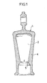
La figure 1 illustre schématiquement en coupe une ferrure 1 de ce genre et sa cavité 2. Afin de faciliter l'ancrage d'un jonc dans cette ferrure on prévoit généralement une paroi latérale 4 formant un rétrécissement intérieur 5 de diamètre d.FIG. 1 schematically illustrates in section a fitting 1 of this kind and its
On conçoit que le moulage d'une telle ferrure est d'autant plus délicat que le rapport du diamètre d a la hauteur de la cavité est plus faible. En outre, une telle géométrie rend presque impossible un contrôle de l'état de surface de la cavité 2.It will be appreciated that the molding of such a fitting is all the more delicate the lower the ratio of the diameter d to the height of the cavity. In addition, such a geometry makes it almost impossible to control the surface condition of the
Pour certains isolateurs ce rapport peut atteindre 1/5. Il est alors pratiquement impossible d'utiliser un noyau en plusieurs parties amovibles pour réaliser la cavité 2.For some insulators this ratio can reach 1/5. It is then practically impossible to use a core in several removable parts to produce the
Le seul procédé utilisable est la coulée sur un noyau de sable. Ce procédé présente de nombreux inconvénients. Tout d'abord, les noyaux de sable laissent un état de surface rugueux ; en outre ils sont légèrement poreux et le dégazage qui apparaît à haute température, et qui ne peut être libéré puisque la cavité est borgne, altère encore l'état de surface. Or cet état de surface doit avoir une qualité qui permet un glissement relatif du matériau d'ancrage sur la surface intérieure de la cavité de la ferrure afin d'obtenir un "auto-blocage" par un effet de coincement. On obtient ainsi une résistance spécifique élevée de l'ancrage du jonc ainsi réalisé.The only usable process is casting on a core of sand. This process has many drawbacks. First, the sand cores leave a rough surface state; in addition they are slightly porous and the degassing which appears at high temperature, and which cannot be released since the cavity is blind, further deteriorates the surface condition. However, this surface condition must have a quality which allows relative sliding of the anchoring material on the interior surface of the cavity of the fitting in order to obtain a "self-locking" action by a wedging effect. A high specific resistance is thus obtained from the anchoring of the rod thus produced.
La présente invention a pour but de proposer un procédé de fabrication d'une ferrure permettant l'obtention d'un état de surface interne satisfaisant.The object of the present invention is to propose a method of manufacturing a fitting making it possible to obtain a satisfactory internal surface condition.
La présente invention a pour objet un procédé de fabrication d'une ferrure d'extrémité d'un isolateur électrique composite, ferrure comportant une cavité interne à état de surface prédéterminé pour recevoir l'extrémité scellée d'un jonc isolant ; pour cela on réalise séparément deux parties complémentaires présentant ledit état de surface par un procédé choisi parmi la coulée sur un noyau métallique, ou l'estampage, le matriçage, l'emboutissage d'une tôle ; puis on solidarise l'une à l'autre lesdites parties complémentaires par un procédé d'assemblage du type soudure, sertissage, rivetage, le raccord de solidarisation étant suffisamment fin pour ne pas altérer ledit état de surface et laisser la possibilité de glissement pour "l'auto-blocage" explicité plus haut.The present invention relates to a method of manufacturing an end fitting of a composite electrical insulator, fitting having an internal cavity with a predetermined surface state to receive the sealed end of an insulating rod; for this, two complementary parts are produced separately having said surface condition by a process chosen from casting on a metal core, or stamping, stamping, stamping of a sheet metal; then said complementary parts are joined to one another by an assembly process of the welding, crimping, riveting type, the joining connector being sufficiently fine so as not to alter said surface condition and to leave the possibility of sliding for " self-locking "explained above.
Les parties complémentaires peuvent donc être en tout matériau coulable, par exemple en fonte, acier, alliage d'aluminium ou de cuivre.The complementary parts can therefore be made of any flowable material, for example cast iron, steel, aluminum alloy or copper.
Elles peuvent être obtenues à partir d'une tôle, en acier, en aluminium, en bronze ou équivalent.They can be obtained from sheet metal, steel, aluminum, bronze or equivalent.
On peut mettre en oeuvre pour le soudage tout moyen du type soudage par induction puis pression, soudage par "ultra-pression" ou analogue.Any means such as induction welding and pressure welding, welding by "ultra-pressure" or the like can be used for welding.
Les parties complémentaires peuvent être identiques, et leur zone de contact est alors située dans un plan de symétrie de la ferrure. Mais les faces de contact peuvent présenter des zones plus ou moins crénelées ou ondulées favorisant leur solidarisation ou emboîtement mutuel.The complementary parts can be identical, and their contact zone is then located in a plane of symmetry of the fitting. However, the contact faces may have more or less crenellated or wavy zones favoring their joining or mutual interlocking.
Il est particulièrement avantageux de prévoir en outre une frette métallique au moins autour de la portion de la ferrure susceptible de subir le plus de contraintes mécaniques.
Cette frette est mise en place par un procédé connu en soi. Elle peut être soudée à la ferrure. Son matériau est choisi de manière à avoir un coefficient de dilatation compatible avec celui des parties complémentaires de la ferrure.It is particularly advantageous to further provide a metal hoop at least around the portion of the fitting capable of undergoing the most mechanical stresses.
This hoop is put in place by a process known per se. It can be welded to the fitting. Its material is chosen so as to have a coefficient of expansion compatible with that of the complementary parts of the fitting.
On pourra prévoir également des moyens de consolidation des zones assemblées, extérieurs aux parties complémentaires. Ces dernières peuvent comporter des rainures d'ancrage pour des clavettes de sécurité.Means may also be provided for consolidating the assembled zones, external to the complementary parts. The latter may include anchoring grooves for safety keys.
D'autres caractéristiques et avantages de l'invention apparaîtront au cours de la description qui sera faite à l'aide (1.. dessin annexé donné à titre illustratif mais nullement limitatif et dans lequel :
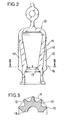
- - la figure 2 montre en élévation une partie complémentaire d'une ferrure selon l'invention,
- - la figure 3 est une vue en coupe selon la ligne III-III de la figure 2,
- - la figure 4 montre en élévation une variante de réalisation de la ferrure de la figure 2,
- - la figure 5 est une vue en coupe selon la ligne V-V de la figure 4,
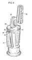
- - la figure 6 est une vue en perspective d'une autre variante de réalisation.
- FIG. 2 shows in elevation a complementary part of a fitting according to the invention,
- FIG. 3 is a sectional view along line III-III of FIG. 2,
- FIG. 4 shows in elevation an alternative embodiment of the fitting of FIG. 2,
- FIG. 5 is a sectional view along the line VV in FIG. 4,
- - Figure 6 is a perspective view of another alternative embodiment.
On voit sur les figures 2 et 3 une demi-ferrure 10 selon l'invention. Cette demi-ferrure a été moulée et son état de surface a pu être parfaitement contrôlé. Après soudage des faces en regard 14 des deux demi-ferrures, on entoure la partie de la ferrure comprise entre sa partie supérieure et l'étranglement 15 d'une frette cylindrique monobloc 11. La partie frettée est susceptible de supporter des contraintes mécaniques importantes.FIGS. 2 and 3 show a half-fitting 10 according to the invention. This half-fitting was molded and its surface condition could be perfectly checked. After welding the facing
La frette est mise en place par un procédé connu en soi sur des nervures 12 venues de moulage avec la paroi de la demi-ferrure 10. Ces nervures présentent chacune un épaulement 16 qui sert de butée à la frette 11. Cette dernière peut être soudée localement à la paroi de la ferrure. On voit sur la figure 3 la forme polygonale prise par la frette 11 après son rétreint.The hoop is put in place by a process known per se on
Les figures 4 et 5 montrent une autre variante de demi-ferrure 20 selon l'invention, qui n'est pas moulée mais réalisée à partir d'une tôle en un métal déformable. L'extrémité 22 de la demi-ferrure 20 est percée ou découpée en 21 après le formage de cette dernière.Figures 4 and 5 show another variant of half-fitting 20 according to the invention, which is not molded but made from a sheet of a deformable metal. The
Pour renforcer l'ensemble formé par les demi-ferrures soudées, on réalise autour de la zone la plus sollicitée mécaniquement une frette 23 par coulée dans un moule dont on voit une demi-coquille 24 dans la figure 4. Le matériau de la frette 23 est choisi en un alliage approprié qui provoque une pré-contrainte sur les demi-ferrures au moment de son refroidissement, par retrait.To reinforce the assembly formed by the welded half-fittings, a
On voit sur la figure 5 une coupe des deux demi-ferrures 20 et 30 soudées entre elles et munies de leur frette 23.FIG. 5 shows a section of the two half-
On a repéré 25 la zone de soudure et on remarquera que les demi-ferrures 20 et 30 sont plus épaisses au niveau de cette zone.The weld zone has been identified and it will be noted that the half-
La figure 6 illustre un autre mode de réalisation sans mise en oeuvre de frette. Les deux demi-ferrures 41 et 42 sont soudées suivant une surface, dont on voit la ligne extérieure 40 ; au voisinage de la soudure, les parois coniques des demi-ferrures présentent des rebords en équerre 43 et 44 définissant deux logements pour les bords 45 et 46 d'une clavette 51. Une seconde clavette 52 est prévue pour renforcer la surface de soudure opposée. La partie supérieure des clavettes peut être éventuellement obturée.FIG. 6 illustrates another embodiment without using a hoop. The two half-
Bien entendu, l'invention n'est pas limitée aux modes de réalisation qui viennent d'être décrits. Au lieu de souder les faces en contact des deux demi-ferrures, on peut les sertir ou les riveter, ou utiliser tout autre mode d'assemblage équivalent sans sortir du cadre de l'invention.Of course, the invention is not limited to the embodiments which have just been described. Instead of welding the contacting faces of the two half-fittings, they can be crimped or riveted, or use any other equivalent assembly method without departing from the scope of the invention.
Claims (6)
Applications Claiming Priority (2)
| Application Number | Priority Date | Filing Date | Title |
|---|---|---|---|
| FR8110772 | 1981-06-01 | ||
| FR8110772A FR2506998A1 (en) | 1981-06-01 | 1981-06-01 | METHOD FOR MANUFACTURING AN ELECTRIC INSULATOR END FITTING |
Publications (1)
| Publication Number | Publication Date |
|---|---|
| EP0066262A1 true EP0066262A1 (en) | 1982-12-08 |
Family
ID=9259043
Family Applications (1)
| Application Number | Title | Priority Date | Filing Date |
|---|---|---|---|
| EP82104642A Withdrawn EP0066262A1 (en) | 1981-06-01 | 1982-05-27 | Method of making a metal end fitting for an electrical insulator |
Country Status (2)
| Country | Link |
|---|---|
| EP (1) | EP0066262A1 (en) |
| FR (1) | FR2506998A1 (en) |
Cited By (1)
| Publication number | Priority date | Publication date | Assignee | Title |
|---|---|---|---|---|
| WO2000011685A1 (en) * | 1998-08-18 | 2000-03-02 | Siemens Aktiengesellschaft | Device for connecting a first overhead line component comprising an axial end part, to at least one second overhead line component |
Citations (3)
| Publication number | Priority date | Publication date | Assignee | Title |
|---|---|---|---|---|
| CH152055A (en) * | 1930-10-31 | 1932-01-15 | Matthey Charles | Insulator. |
| CH504085A (en) * | 1970-02-12 | 1971-02-28 | Dietz Alfred | Suspension isolator |
| GB1233310A (en) * | 1969-08-04 | 1971-05-26 |
-
1981
- 1981-06-01 FR FR8110772A patent/FR2506998A1/en active Granted
-
1982
- 1982-05-27 EP EP82104642A patent/EP0066262A1/en not_active Withdrawn
Patent Citations (3)
| Publication number | Priority date | Publication date | Assignee | Title |
|---|---|---|---|---|
| CH152055A (en) * | 1930-10-31 | 1932-01-15 | Matthey Charles | Insulator. |
| GB1233310A (en) * | 1969-08-04 | 1971-05-26 | ||
| CH504085A (en) * | 1970-02-12 | 1971-02-28 | Dietz Alfred | Suspension isolator |
Cited By (1)
| Publication number | Priority date | Publication date | Assignee | Title |
|---|---|---|---|---|
| WO2000011685A1 (en) * | 1998-08-18 | 2000-03-02 | Siemens Aktiengesellschaft | Device for connecting a first overhead line component comprising an axial end part, to at least one second overhead line component |
Also Published As
| Publication number | Publication date |
|---|---|
| FR2506998A1 (en) | 1982-12-03 |
| FR2506998B1 (en) | 1984-01-06 |
Similar Documents
| Publication | Publication Date | Title |
|---|---|---|
| EP0335781B1 (en) | Composite material body for a transmission joint, and method of manufacturing same | |
| EP3766715B1 (en) | Reinforcing insert provided with through-holes | |
| EP2307587B1 (en) | Method for producing a metallic part reinforced by ceramic fibres | |
| FR2627821A1 (en) | ANTI-VIBRATION FIXING DEVICE, ESPECIALLY A CARBON PLATE ON THE BEARING DOOR FLANGE OF AN ELECTRIC MOTOR | |
| EP1075929B1 (en) | Rigid core in two parts, for manufacturing tires | |
| EP2554080B1 (en) | A method of manufacturing a cooking vessel with controlled deformation and cooking vessel obtained | |
| CA2201524A1 (en) | Automobile wheel and process for manufacturing it | |
| FR2691219A1 (en) | Bearing bearing. | |
| FR2732155A1 (en) | COMPRESSION MOLD DEVICE FOR MANUFACTURING A COMPOSITE INSULATOR | |
| FR2677723A1 (en) | Device for elastic connection between two components, method for manufacturing this device, and installation for implementing this method | |
| EP0066262A1 (en) | Method of making a metal end fitting for an electrical insulator | |
| EP2310547B1 (en) | Method for producing a metallic part comprising inner reinforcements consisting of ceramic fibres | |
| EP3280563B1 (en) | Assembly method for attaching a first part to a second part | |
| EP0562949A1 (en) | Method for assembling the extremities of two elements placed in front of each other and dismountable chain link produced with such method | |
| CH677250A5 (en) | ||
| FR2772662A1 (en) | Force distribution insert | |
| EP1383141A1 (en) | Manufacturing of a composite insulator body | |
| EP0887810B1 (en) | Metal fitting for composite insulator | |
| FR2913916A1 (en) | HOLLOW PNEUMATIC. | |
| EP0340083A1 (en) | Ignition coil for internal combustion engines of automobile vehicles and process of fabrication | |
| EP0836539B1 (en) | Internal nozzle/plate assembly comprising a weakened portion | |
| FR2706096A1 (en) | Method of manufacturing a rotor in a magneto-generator | |
| EP0119467A1 (en) | Process for fixing a malleable metallic jacket to a rod of composite material, and insulator produced by carrying out this process | |
| FR2752769A1 (en) | Composite, sandwich panel with reinforced anchorage point for automobile construction | |
| FR2536848A1 (en) | HOLLOW LOAD |
Legal Events
| Date | Code | Title | Description |
|---|---|---|---|
| PUAI | Public reference made under article 153(3) epc to a published international application that has entered the european phase |
Free format text: ORIGINAL CODE: 0009012 |
|
| AK | Designated contracting states |
Designated state(s): AT BE CH DE FR GB IT LU NL SE |
|
| 17P | Request for examination filed |
Effective date: 19830530 |
|
| STAA | Information on the status of an ep patent application or granted ep patent |
Free format text: STATUS: THE APPLICATION IS DEEMED TO BE WITHDRAWN |
|
| 18D | Application deemed to be withdrawn |
Effective date: 19841201 |
|
| RIN1 | Information on inventor provided before grant (corrected) |
Inventor name: KACZERGINSKI, ALEXANDRE Inventor name: PARGAMIN, LAURENT |