EP0065870B1 - Sitzlehne mit verstellbarer Lendenstütze - Google Patents
Sitzlehne mit verstellbarer Lendenstütze Download PDFInfo
- Publication number
- EP0065870B1 EP0065870B1 EP82302547A EP82302547A EP0065870B1 EP 0065870 B1 EP0065870 B1 EP 0065870B1 EP 82302547 A EP82302547 A EP 82302547A EP 82302547 A EP82302547 A EP 82302547A EP 0065870 B1 EP0065870 B1 EP 0065870B1
- Authority
- EP
- European Patent Office
- Prior art keywords
- cam
- lumbar support
- follower
- support position
- cam surface
- Prior art date
- Legal status (The legal status is an assumption and is not a legal conclusion. Google has not performed a legal analysis and makes no representation as to the accuracy of the status listed.)
- Expired
Links
- 230000001105 regulatory effect Effects 0.000 claims description 22
- 230000003319 supportive effect Effects 0.000 claims description 5
- 239000002184 metal Substances 0.000 description 2
- 238000006073 displacement reaction Methods 0.000 description 1
- 210000005069 ears Anatomy 0.000 description 1
- 239000000463 material Substances 0.000 description 1
- 230000002787 reinforcement Effects 0.000 description 1
- 238000003466 welding Methods 0.000 description 1
Images

Classifications
-
- B—PERFORMING OPERATIONS; TRANSPORTING
- B60—VEHICLES IN GENERAL
- B60N—SEATS SPECIALLY ADAPTED FOR VEHICLES; VEHICLE PASSENGER ACCOMMODATION NOT OTHERWISE PROVIDED FOR
- B60N2/00—Seats specially adapted for vehicles; Arrangement or mounting of seats in vehicles
- B60N2/64—Back-rests or cushions
- B60N2/66—Lumbar supports
Definitions
- This invention relates generally to vehicle seats and more particularly to a seat backrest which includes a lumbar support regulating apparatus which is manually adjustable to provide a particular lumbar contour for the occupant of the seat.
- a support plate is located at the lower end of a retaining leaf spring.
- a pin extends transversely from the upper end of the spring and is adapted to sit in a selected of transverse grooves disposed one below the other in a mounting.
- the plate is adjusted vertically relatively to the back of a seat by locating the pin in an appropriate groove.
- the leaf spring, and hence the plate, is adjusted with respect to the depth of the seat by a screw bolt located in a block slidably mounted in the mounting.
- the screw bolt is screwed into the block, and the forward end of the screw bolt is attached to the leaf spring.
- By rotating a knob the screw bolt is advanced or withdrawn with respect to the mounting, so as to vary the inclination of the leaf spring, and hence adjust the position of the plate with respect to the depth of the seat.
- the cam On rotating a handle the cam is rotated causing the spring central portion to move to an appropriate one of the aforementioned cam faces, thereby rotating the spring about the shaft to adjust the lumbar plate relative to the depth of the seat.
- the invention as claimed is intended to alleviate these disadvantages. It includes a cam- lever mechanism providing an appreciable mechanical advantage over the screw threaded system of GB-A-849798. It also includes a coacting finger and protuberance which limits excessive rotation of a cam and incorrect adjustment of the lumbar support plate.
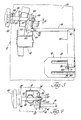
- a lumbar support regulating apparatus constructed according to the present invention is indicated collectively by reference numeral 10 and includes a seat back 12 having a rigid frame 14.
- a bar 16 is povitally mounted on the frame 14.
- a lumbar support plate 18, a cantilevered rigid or resilient element which may take the form of a leaf spring 20, a rigid follower 22 and a manually operated regulating means are also mounted on the frame 14.
- the seat back 12 may be pivotally connected in a conventional fashion to the seat portion of a vehicle seat or the seat back 12 may be fixedly mounted relative to the seat portion of the vehicle seat.
- the lumbar support plate 18 is located in position at the lumbar area of the seat back 12 in moving relation thereto and behind a cushioned backrest portion 26 of the seat back 12 whereby the backrest portion 26 can be adjusted in the lumbar area to accommodate the support needs of any particular user of the vehicle seat by a greater or lesser projection of the backrest. portion 26 in the lumbar area after movement of the lumbar support plate 18 as will be described in greater detail hereinafter.
- the regulating apparatus 10 further maintains the selected comfort contour by preventing the lumbar support plate 18 from moving out of its selected position.
- the lumbar support plate 18 comprises a plate member 28 which may be either flexible or rigid.
- the plate member 28 is provided with a pair of outwardly curved ridges 30 and 32.
- Material struck from a pair of apertures in the plate member 28, only one of which is shown at 34 in Figure 3, provides rearwardly projecting pairs of parallel attachment ears 36 between and through which extend a connecting rod or pivot 38 also received through flanges 40 on the lower end portion of the downwardly extending spring leaf member 20.
- the upper end portion of the spring leaf member 20 is formed with an upwardly extending groove 42 and receives therein a central portion of the bent rod 16 and is fixedly secured thereto, such as by welding.
- the frame 16 and, in particular, a sheet metal plate 44 thereof, pivotally supports one end portion 46 of the bar 16.
- the opposite end portion of the bent rod 16 is also supported for pivotal movement but is not shown for the sake of simplicity.
- the supported end portion 46 of the bent rod 16 is secured to the plate 44 by a transversely extending pin 48 which extends through the bent rod 16 at the end portion 46.
- a lower end portion 50 of the follower 22 is fixedly secured to the end portion 46 of the bent rod 16 by a pin 52 which extends through the end portion 50 and the end portion 48.
- An upper end portion of tongue 54 of the follower 22 is adapted to ride upon or follow the outer circumferential surface of a cam 56 of the regulating mechanism 24.
- the cam 56 which may be made of any suitable plastic or metal, is secured on a keyed portion 59 of a shaft 68 between an enlarged shoulder portion 60 of the shaft and a bearing 62.
- the operating shaft 58 has a handle 64 mounted on the opposite end thereof and is fixedly secured thereto by a pin 66.
- the shaft 58 is rotatably supported in an aperture 68 extending through a front collar portion 70 of the frame 14.
- the shaft 58 is also rotatably supported in a rear collar . portion 72 of the frame 14.
- the cam 56 is rotated by turning the handle 64 which rotates the shaft 58.
- a retaining ring 74 holds the shaft
- the cam 56 is provided with a single cam face 76 which is adapted to engage the tongue 54 of the follower 22.
- the cam surface 76 is provided with recesses 77, 78, 79, 80 and 81 in which the tongue 54 of the follower 22 will rest in each adjusted position. Those portions of the cam surface between adjacent recesses are gradually sloping except for that portion between the recesses 81 and 84.
- the recesses 77 through 80 are formed in the cam surface 76 such that when the tongue 54 is disposed in any one of the recesses 77 through 80, the force transmitted to the follower 22 from the leaf spring 20 is directed towards the center of the axis of rotation of the cam 56 so as not to create any forces which would rotate the cam 56.
- the tongue 54 Upon rotation of the cam 56 in a first counterclockwise direction, the tongue 54 will move upwardly out of an indented portion 84 of the cam 56 to place the tongue 54 in a first recess 77 which represents a first lumbar support position. As long as the tongue 54 is in the indented portion 84, the support plate 18 is in its free, non-supportive position as shown in Figure 1. Thereafter, further rotation of the cam 56 causes the tongue 54 to smoothly ride along the cam surface 76 to one of the intermediate recesses 78, 79 or 80.
- the recesses 77 through 81 are spaced along the cam surface 76 so that as the cam 56 rotates in a counterclockwise direction as shown in Figure 2, the tongue 54 of the follower 22 travels a greater and greater distance along the cam surface 76 in order to obtain the same increase in distance that the tongue is from the axis of rotation of the cam 56.
- the tongue 54 must travel a greater and greater distance along the surface 76 in order to displace the tongue 54 a given distance away from the axis of the rotation of the cam 56. This, in turn, causes the bent bar or rod 16 to rotate and thereby vary the position of the lumbar support plate 18.
- the cam 56 also includes a nose or protuberance 86 which extends radially above the cam surface 76 immediately adjacent the last lumbar support position indicated by the recess 81.
- the protuberance 86 prevents movement of the tongue 54 from the last lumbar support position towards the first lumbar support position indicated by the recess 77 as the cam 56 rotates in a counterclockwise direction. Consequently, the cam 56 must be rotated in a clockwise position from the last lumbar support position indicated by the recess 81 in order to move the tonque 54 in any one of the other recesses 77 through 80 or to place the tongue 54 in the indented portion 84.
- the spring force from the leaf spring 20 and through the follower 22 will be directed away from the axis of rotation of the cam 56 thereby tending to cause the cam 56 to rotate in a clockwise direction. Because of this, the cam 56 will be more securely held in the last lumbar support position to counteract the relatively large force exerted through the leaf spring 20.
- the lumbar support regulating apparatus 10 is operated by rotating the handle 24 in a counterclockwise position as shown in Figures 1 or 2 to progressively adjust the firmness of the backrest 26 from soft, to medium and to hard. Consequently, the cam 56 will also be rotated in a counterclockwise direction about the axis of the shaft 58 so that the tongue 54 of the follower 22 will be sequentially engaged on the cam surface 76 between the recesses 77 and 78, between the recesses 78 and 79, between the recesses 79 and 80 and between the recesses 80 and 81.
- the distances on the cam face 76 from the center of rotation of the shaft 58 progressively increase which will tend to rotate the follower 22 away from the axis of rotation of the cam 56 and, consequently, rotate the bar 16.
- the bar 16 causes the leaf spring 20 to act with increasing force on the lumbar support plate 18 as the cam 56 is rotated.
- the specific configuration of the cam surface 76 provides a greater mechanical advantage for the user of the apparatus 10 which is necessary to overcome the greater and greater force exerted by the leaf spring 20 on the lumbar support plate 18.
- the engagement of the tongue 54 with the recesses 77 through 81 will secure pull the cam 56 in its adjusted position.
- the indented portion 84 of the cam 56 provides the apparatus 10 with a rest or non-supportive position.
- the protuberance 86 of the cam 56 allows substantially the entire cam surface 76 to be utilized to cam the tongue 54 of the follower 22 and also allow the recess 81 to be formed in such a fashion that force exerted by the leaf spring 20 through the tongue 54 will be directed away from the center of the axis of rotation of the cam 56 to more securely hold the cam 56 in the last lumbar support position.
Landscapes
- Engineering & Computer Science (AREA)
- Aviation & Aerospace Engineering (AREA)
- Transportation (AREA)
- Mechanical Engineering (AREA)
- Chair Legs, Seat Parts, And Backrests (AREA)
Claims (4)
Applications Claiming Priority (2)
| Application Number | Priority Date | Filing Date | Title |
|---|---|---|---|
| US06/267,127 US4449751A (en) | 1981-05-26 | 1981-05-26 | Seat backrest having an adjustable lumbar support |
| US267127 | 1981-05-26 |
Publications (2)
| Publication Number | Publication Date |
|---|---|
| EP0065870A1 EP0065870A1 (de) | 1982-12-01 |
| EP0065870B1 true EP0065870B1 (de) | 1986-04-16 |
Family
ID=23017424
Family Applications (1)
| Application Number | Title | Priority Date | Filing Date |
|---|---|---|---|
| EP82302547A Expired EP0065870B1 (de) | 1981-05-26 | 1982-05-19 | Sitzlehne mit verstellbarer Lendenstütze |
Country Status (5)
| Country | Link |
|---|---|
| US (1) | US4449751A (de) |
| EP (1) | EP0065870B1 (de) |
| AU (1) | AU543373B2 (de) |
| CA (1) | CA1190467A (de) |
| MX (1) | MX158894A (de) |
Families Citing this family (39)
| Publication number | Priority date | Publication date | Assignee | Title |
|---|---|---|---|---|
| DE3306994A1 (de) * | 1983-02-28 | 1984-08-30 | P.A. Rentrop Hubbert & Wagner Fahrzeugausstattungen GmbH & Co KG, 3060 Stadthagen | Sitz, insbesondere kraftfahrzeugsitz |
| JPS59137151U (ja) * | 1983-03-03 | 1984-09-13 | アイシン精機株式会社 | ランバ−サポ−ト |
| JPS60207614A (ja) * | 1984-03-29 | 1985-10-19 | 株式会社タチエス | ランバ−サポ−ト装置 |
| JPS6266810A (ja) * | 1985-09-19 | 1987-03-26 | アイシン精機株式会社 | ランバ−サポ−ト装置 |
| US4725095A (en) * | 1986-07-11 | 1988-02-16 | Johnson Service Company | Vehicle seat with mechanical lumbar support having two degrees of freedom |
| GB2196530B (en) * | 1986-11-01 | 1990-01-17 | Jmh Holdings Ltd | A seat with a movable lumbar support device |
| AT394829B (de) | 1989-08-04 | 1992-06-25 | Schuster Wilhelm | Rueckenlehne fuer einen fahrzeugsitz, mit einer verstellbaren lendenstuetze |
| US5286087A (en) * | 1992-11-09 | 1994-02-15 | Hoover Universal, Inc. | Seat assembly with lumbar support mechanism |
| DE4320105C1 (de) * | 1993-06-17 | 1994-10-13 | Ameu Management Corp | Verstellvorrichtung für ein biegeelastisches Stützelement einer Rückenlehne |
| US5609394A (en) * | 1996-02-23 | 1997-03-11 | Ligon Brothers Manufacturing Company | Four-way lumbar support |
| US6007150A (en) * | 1998-03-08 | 1999-12-28 | Milsco Manufacturing Company | Motorcycle seat with adjustable backrest |
| US6616227B2 (en) | 2001-02-21 | 2003-09-09 | Schukra North America | Powered actuator for lumbar unit |
| US6619739B2 (en) * | 2001-03-01 | 2003-09-16 | L & P Property Management Company | Universal ergonomic support with self-contained actuator |
| US6758522B2 (en) | 2001-03-29 | 2004-07-06 | L&P Property Management Company | Apparatus and method for varying coefficients of friction in a variable apex back support |
| CN100486837C (zh) | 2001-10-11 | 2009-05-13 | L&P产权管理公司 | 装有动力的腰部机构 |
| US6652028B2 (en) * | 2001-11-02 | 2003-11-25 | L & P Property Management | Apparatus and method for lumbar support with variable apex |
| US6676214B2 (en) | 2001-11-16 | 2004-01-13 | L & P Property Management Company | Method and apparatus for lumbar support with integrated actuator housing |
| US6908152B2 (en) | 2001-12-14 | 2005-06-21 | L & P Property Management Company | Push lumbar support with flexible pressure surface |
| US6779844B2 (en) | 2001-12-14 | 2004-08-24 | L&P Propety Maqnagement Company | Arching lumbar support with weight distribution surface |
| US6652029B2 (en) | 2001-12-20 | 2003-11-25 | L & P Property Management Company | Unitized back plate and lumbar support |
| US6908153B2 (en) | 2002-12-02 | 2005-06-21 | L&P Property Management Company | Power lumbar support cable apparatus and method |
| US7052087B2 (en) | 2002-12-09 | 2006-05-30 | L&P Property Management Company | Method and apparatus for a scissors ergonomic support |
| US7137664B2 (en) * | 2003-01-22 | 2006-11-21 | L&P Property Management Company | Automatically actuating ergonomic support system for a fold down seat |
| US6905170B2 (en) * | 2003-01-22 | 2005-06-14 | L & P Property Management Company | Fold down seat lumbar support apparatus and method |
| US7140680B2 (en) * | 2003-01-22 | 2006-11-28 | L&P Property Management Company | Fold down seat lumbar support apparatus and method |
| US7775595B2 (en) * | 2004-02-06 | 2010-08-17 | Schukra Of North America | Drive mechanism |
| EP1771315B1 (de) | 2004-07-30 | 2008-12-10 | L&P Property Management Company | Modulare lumbalstützvorrichtung |
| EP1680983B1 (de) * | 2005-01-12 | 2012-11-28 | L&P Swiss Holding Company | Sitzstruktur umfassend eine Kupplungseinheit |
| EP1680984B1 (de) | 2005-01-12 | 2007-08-15 | L&P Swiss Holding Company | Lendenstützvorrichtung und entsprechende Sitzstruktur |
| US20060267382A1 (en) * | 2005-05-18 | 2006-11-30 | Schukra Of North America | Arm rest return |
| WO2007112564A1 (en) * | 2006-03-30 | 2007-10-11 | Schukra Of North America, Ltd. | Combination lumbar-bolster system |
| US7614696B2 (en) | 2006-12-11 | 2009-11-10 | Schukra Of North America | Lumbar system for climate seating |
| US7984949B2 (en) * | 2007-04-24 | 2011-07-26 | Schukra Of North America | Lumbar and bolster support for second row seat |
| US7997650B2 (en) | 2008-02-22 | 2011-08-16 | Schukra Of North America | Constant pressure retreating lumbar system |
| WO2011149957A2 (en) * | 2010-05-24 | 2011-12-01 | Banyan Licensing, L.L.C. | Adjustable support apparatus |
| USD697726S1 (en) | 2012-09-20 | 2014-01-21 | Steelcase Inc. | Chair |
| US11304528B2 (en) | 2012-09-20 | 2022-04-19 | Steelcase Inc. | Chair assembly with upholstery covering |
| KR101672718B1 (ko) * | 2015-02-27 | 2016-11-04 | (주) 현대기업 | 4-방향 럼버 서포트 |
| US11246420B1 (en) | 2019-03-01 | 2022-02-15 | Ashley Furniture Industries, Llc | Adjustable lumbar support |
Family Cites Families (12)
| Publication number | Priority date | Publication date | Assignee | Title |
|---|---|---|---|---|
| US2139028A (en) * | 1937-09-29 | 1938-12-06 | Elizabeth M Mensendicck | Seat |
| DE1121944B (de) * | 1958-09-26 | 1962-01-11 | Johann Schwarz | Rueckenlehne, insbesondere fuer Kraftfahrzeugsitze |
| AU5853373A (en) * | 1972-10-24 | 1975-01-30 | Ford Motor Canada | Reclining car seat |
| US3807794A (en) * | 1972-12-29 | 1974-04-30 | Ford Motor Co | Lumbar support mechanism |
| US3890000A (en) * | 1973-12-03 | 1975-06-17 | Dura Corp | Adjustable lumbar area support for vehicle seatbacks |
| US3973797A (en) * | 1975-03-31 | 1976-08-10 | Deere & Company | Seat backrest having an adjustable lumbar support |
| JPS5357620A (en) * | 1976-11-01 | 1978-05-25 | Aisin Seiki Co Ltd | Lumber support adjusting apparatus |
| JPS53145778A (en) * | 1977-05-25 | 1978-12-19 | Nissan Motor | Seat with huckleback supporting device |
| JPS5521906A (en) * | 1978-07-31 | 1980-02-16 | Nissan Motor | Seat provided with lumbar support device |
| GB2035071A (en) * | 1978-11-18 | 1980-06-18 | Uop Inc | Seat having a movable lumbar support |
| US4182533A (en) * | 1978-12-26 | 1980-01-08 | Uop Inc. | Seat backrest having an adjustable lumbar support |
| FR2465442A1 (fr) * | 1979-09-25 | 1981-03-27 | Faure Bertrand | Perfectionnements aux dossiers de sieges, notamment pour vehicules |
-
1981
- 1981-05-26 US US06/267,127 patent/US4449751A/en not_active Expired - Fee Related
-
1982
- 1982-02-02 AU AU80130/82A patent/AU543373B2/en not_active Ceased
- 1982-02-11 CA CA000396104A patent/CA1190467A/en not_active Expired
- 1982-04-07 MX MX192194A patent/MX158894A/es unknown
- 1982-05-19 EP EP82302547A patent/EP0065870B1/de not_active Expired
Also Published As
| Publication number | Publication date |
|---|---|
| EP0065870A1 (de) | 1982-12-01 |
| US4449751A (en) | 1984-05-22 |
| MX158894A (es) | 1989-03-29 |
| CA1190467A (en) | 1985-07-16 |
| AU8013082A (en) | 1982-12-02 |
| AU543373B2 (en) | 1985-04-18 |
Similar Documents
| Publication | Publication Date | Title |
|---|---|---|
| EP0065870B1 (de) | Sitzlehne mit verstellbarer Lendenstütze | |
| US4469374A (en) | Automotive seat | |
| US6511130B2 (en) | Head restraint for a vehicle seat | |
| US4531779A (en) | Automotive seat with lumbar support | |
| JP2000517200A (ja) | 座席用背中サポート構造 | |
| US20110163574A1 (en) | Automatically Adjustable Head Restraint | |
| US4811986A (en) | Adjustable lumbar support | |
| US4682817A (en) | Adjustable head restraint for vehicular seats | |
| GB2106380A (en) | Head-rest for use in passenger motor vehicles | |
| AU2002335941A1 (en) | Pivotable boat seat | |
| WO2003039945A1 (en) | Pivotable boat seat | |
| EP0185536B1 (de) | Verstellbare Fahrzeugsitze | |
| US5078449A (en) | Lumbar support device | |
| US4550949A (en) | Lumbar support device | |
| JP7405830B2 (ja) | シート旋回制限装置 | |
| JPH07315088A (ja) | 車両用シート | |
| US4335917A (en) | Reclining arrangement | |
| GB1573254A (en) | Controllably adjustable hinge fittings | |
| KR100228089B1 (ko) | 헤드 레스트 틸트 어셈블리 | |
| JPH10262776A (ja) | 自動車用シート | |
| JP4315333B2 (ja) | 車両用シートのヘッドレスト | |
| JPH0729003Y2 (ja) | 車両用シート | |
| JPH1080338A (ja) | 自動車用シート | |
| US20220063465A1 (en) | Adjustment mechanism and headrest | |
| JPS6315063Y2 (de) |
Legal Events
| Date | Code | Title | Description |
|---|---|---|---|
| PUAI | Public reference made under article 153(3) epc to a published international application that has entered the european phase |
Free format text: ORIGINAL CODE: 0009012 |
|
| AK | Designated contracting states |
Designated state(s): CH FR GB |
|
| 17P | Request for examination filed |
Effective date: 19830518 |
|
| GRAA | (expected) grant |
Free format text: ORIGINAL CODE: 0009210 |
|
| AK | Designated contracting states |
Kind code of ref document: B1 Designated state(s): CH FR GB LI |
|
| ET | Fr: translation filed | ||
| PLBE | No opposition filed within time limit |
Free format text: ORIGINAL CODE: 0009261 |
|
| STAA | Information on the status of an ep patent application or granted ep patent |
Free format text: STATUS: NO OPPOSITION FILED WITHIN TIME LIMIT |
|
| 26N | No opposition filed | ||
| PGFP | Annual fee paid to national office [announced via postgrant information from national office to epo] |
Ref country code: GB Payment date: 19900511 Year of fee payment: 9 |
|
| PGFP | Annual fee paid to national office [announced via postgrant information from national office to epo] |
Ref country code: FR Payment date: 19900525 Year of fee payment: 9 |
|
| PGFP | Annual fee paid to national office [announced via postgrant information from national office to epo] |
Ref country code: CH Payment date: 19900528 Year of fee payment: 9 |
|
| PG25 | Lapsed in a contracting state [announced via postgrant information from national office to epo] |
Ref country code: GB Effective date: 19910519 |
|
| PG25 | Lapsed in a contracting state [announced via postgrant information from national office to epo] |
Ref country code: LI Effective date: 19910531 Ref country code: CH Effective date: 19910531 |
|
| GBPC | Gb: european patent ceased through non-payment of renewal fee | ||
| PG25 | Lapsed in a contracting state [announced via postgrant information from national office to epo] |
Ref country code: FR Effective date: 19920131 |
|
| REG | Reference to a national code |
Ref country code: CH Ref legal event code: PL |
|
| REG | Reference to a national code |
Ref country code: FR Ref legal event code: ST |