EP0065736A2 - Procédé et appareil pour la fabrication d'une botte d'armature - Google Patents
Procédé et appareil pour la fabrication d'une botte d'armature Download PDFInfo
- Publication number
- EP0065736A2 EP0065736A2 EP82104307A EP82104307A EP0065736A2 EP 0065736 A2 EP0065736 A2 EP 0065736A2 EP 82104307 A EP82104307 A EP 82104307A EP 82104307 A EP82104307 A EP 82104307A EP 0065736 A2 EP0065736 A2 EP 0065736A2
- Authority
- EP
- European Patent Office
- Prior art keywords
- feed
- reinforcement
- wires
- reinforcing
- bundle
- Prior art date
- Legal status (The legal status is an assumption and is not a legal conclusion. Google has not performed a legal analysis and makes no representation as to the accuracy of the status listed.)
- Granted
Links
- 230000003014 reinforcing effect Effects 0.000 title claims abstract description 36
- 238000000034 method Methods 0.000 title claims description 11
- 238000004519 manufacturing process Methods 0.000 claims abstract description 23
- 238000003466 welding Methods 0.000 claims abstract description 15
- 238000005452 bending Methods 0.000 claims abstract description 5
- 230000002787 reinforcement Effects 0.000 claims description 91
- 238000005520 cutting process Methods 0.000 claims description 11
- 238000003860 storage Methods 0.000 claims description 2
- 239000011150 reinforced concrete Substances 0.000 claims 2
- 230000008901 benefit Effects 0.000 description 5
- 230000008859 change Effects 0.000 description 3
- 238000013461 design Methods 0.000 description 3
- 238000012545 processing Methods 0.000 description 3
- 229910000746 Structural steel Inorganic materials 0.000 description 2
- 230000002349 favourable effect Effects 0.000 description 2
- 241001136792 Alle Species 0.000 description 1
- 229910000831 Steel Inorganic materials 0.000 description 1
- 230000004913 activation Effects 0.000 description 1
- 230000006978 adaptation Effects 0.000 description 1
- 238000013459 approach Methods 0.000 description 1
- 238000006243 chemical reaction Methods 0.000 description 1
- 230000006835 compression Effects 0.000 description 1
- 238000007906 compression Methods 0.000 description 1
- 230000002950 deficient Effects 0.000 description 1
- 238000006073 displacement reaction Methods 0.000 description 1
- 239000000203 mixture Substances 0.000 description 1
- 230000004048 modification Effects 0.000 description 1
- 238000012986 modification Methods 0.000 description 1
- 230000008569 process Effects 0.000 description 1
- 230000000284 resting effect Effects 0.000 description 1
- 239000010959 steel Substances 0.000 description 1
Images


Classifications
-
- B—PERFORMING OPERATIONS; TRANSPORTING
- B21—MECHANICAL METAL-WORKING WITHOUT ESSENTIALLY REMOVING MATERIAL; PUNCHING METAL
- B21F—WORKING OR PROCESSING OF METAL WIRE
- B21F45/00—Wire-working in the manufacture of other particular articles
- B21F45/006—Wire-working in the manufacture of other particular articles of concrete reinforcement fibres
-
- B—PERFORMING OPERATIONS; TRANSPORTING
- B21—MECHANICAL METAL-WORKING WITHOUT ESSENTIALLY REMOVING MATERIAL; PUNCHING METAL
- B21F—WORKING OR PROCESSING OF METAL WIRE
- B21F23/00—Feeding wire in wire-working machines or apparatus
- B21F23/002—Feeding means specially adapted for handling various diameters of wire or rod
-
- B—PERFORMING OPERATIONS; TRANSPORTING
- B21—MECHANICAL METAL-WORKING WITHOUT ESSENTIALLY REMOVING MATERIAL; PUNCHING METAL
- B21F—WORKING OR PROCESSING OF METAL WIRE
- B21F45/00—Wire-working in the manufacture of other particular articles
-
- E—FIXED CONSTRUCTIONS
- E04—BUILDING
- E04C—STRUCTURAL ELEMENTS; BUILDING MATERIALS
- E04C5/00—Reinforcing elements, e.g. for concrete; Auxiliary elements therefor
- E04C5/01—Reinforcing elements of metal, e.g. with non-structural coatings
- E04C5/02—Reinforcing elements of metal, e.g. with non-structural coatings of low bending resistance
Definitions
- the invention relates to a method for producing a reinforcement bundle, which consists of at least two mutually parallel reinforcement bars that touch each other over the entire length, and a device for carrying it out.
- the bundling of reinforcing bars is particularly favorable for the replacement of single bars of larger diameter, for example from a diameter of 18 mm, whereby the bundling of two, three or four bars brings particular advantages. Since the diameter graduation is generally 1 mm, for larger diameters 2 mm is, a large number of single bars of larger diameter must be replaced by reinforcement bundles.
- the invention has now set itself the task of creating a method which is suitable by means of a simple, rationally usable device for producing reinforcement bundles of any number of bars and any diameter, in preferred embodiments the diameter of the bars also within the bundle are different. and their lengths can be adapted to the course of the bending moment line.
- bundles of two, three or four bars of the same and different diameters and the same or different lengths should be able to be produced in a single automatic production system without significant downtimes, the overall system, in particular the number of reels, being economically justifiable on the reinforcement bundles moved about adjusted extent.
- this object is achieved in that from a number of reinforcement wires wound on reels, which is at least one larger than the number of bars in the bundle of reinforcements to be produced, a number of reinforcement wires corresponding to the number of bars in the bundle is selected by feed devices, a welding device fed, welded together at least some places and cut to the desired length.
- a device suitable for this purpose is characterized by a supply part with reinforcement wires wound on reels and with straightening devices assigned to them, by a selection unit, by a feed unit with controlled selectable feed devices, by an immediately adjoining cutting unit and by a welding unit, the number of reels being at least one is greater than the number of reinforcing bars of the bundle and the ends of all reinforcing wires constantly protrude into the selection unit in which the selected reinforcing wires can be grasped by the feed devices, each feed device preferably consisting of a drive roller and a pinch roller, each drive roller on its own , drivable drive shaft is arranged.
- all reinforcement wires are therefore constantly available in the device, of which only those are selected and processed which are required for the reinforcement bundle to be produced. If, for example, two-bar reinforcement bundles are required, Two of four reinforcement wires inserted into the selection device can be gripped and welded together. The changeover to the production of three-bar bundles is therefore limited to the activation of an additional existing reinforcement wire, which is integrated into the processing process. In order to produce a four-bar bundle, the fourth reinforcing bar resting in the selection device is also included in the production.
- a device with four reinforcement wires of the same thickness is therefore already able to produce three different types of bundles with bars of the same length in any length. If the reinforcement bundles are to be approximated to the torque curve, so that the lengths of the reinforcement bars are staggered, this can be achieved in that the selected reinforcement wires are fed from the individually controllable feed devices to the welding device at the same feed rate and the feed of the selected reinforcement wires is interrupted in reverse order in time, each reinforcement wire being cut off immediately after the interruption of its feed.
- the cutting unit has a number of cutting devices which corresponds to the maximum number of reinforcing bars of the reinforcement bundle and which can be actuated individually in a controlled manner.
- the same device is therefore capable of bundles of two, three or four bars of any length to generate, with the rod lengths adapted to the torque curve from bundle to bundle and therefore different.
- the reinforcement bars have different diameters in the individual bundle.
- three different two-bar bundles, two different three-bar bundles and one four-bar bundle i.e. a total of six different types of bundles, each in any length adapted to the course of the moment, can be produced if only reinforcement wires with successive diameters Diameters can be combined.
- the method suitable for this purpose provides, according to the invention, that the reinforcement wires wound on reels are assigned to the feed devices according to increasing diameter, that from the row of reinforcement wires a group of adjacent reinforcement wires corresponding to the number of bars of the bundle is detected by the feed devices and fed to the welding device, whereby no significant design change of the device described above is required. If the diameters are combined as desired, six different two-bar, four three-bar and one four-bar, i.e. a total of eleven different bundles can be produced, each in any length. The resulting advantage is multiplied particularly when the number of reels is increased.
- the reinforcement wires are provided in the common mean diameters between five and sixteen millimeters, each with a difference of one millimeter, reinforcement bundles are produced, which can replace all the usual single rods, the extent of the stock part being less than the usual width of mesh welding machines.
- the feed unit can have a number of feed devices corresponding to the total number of reinforcing wires, which can be used individually controlled. So only those are switched on, which should convey the desired reinforcement wires.
- a further embodiment of a device provides that the feed unit has a number of feed devices corresponding to the maximum number of reinforcement bars of the reinforcement bundle, all drive rollers and all pinch rollers being combined to form a feed block. and both feed blocks can be displaced in two directions in a plane perpendicular to the working direction and groups of selected reinforcing wires, which project into the selection device next to one another in an ordered manner according to increasing diameter, can be assigned. In this embodiment, significantly fewer feed devices are required, which can be adjusted jointly between the individual feed positions. If, for example, the production of a maximum of four-bar bundles is planned, four feed devices are provided in the feed block, each of which in turn can preferably be driven individually in order to also be able to produce two- and three-bar bundles.
- the ends of the reinforcement wires have two common tangential planes which enclose an angle and each feed block can be displaced parallel to a tangential plane. If the center plane of all reinforcement wires runs horizontally, the displacement paths of the feed blocks to the horizontal each include half the angle of the two tangential planes.
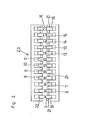
- the device according to FIG. 1 is equipped with a storage part 1, in which twelve reels for reinforcing wires 5 to 16, each of which has a different diameter, are arranged in two rows.
- Each reel is equipped with a conventional balancer arm, not shown or shown, and a spring-loaded brake that is released when the balancer arm is actuated.
- the reels for the reinforcement wires with a diameter from 12 mm, i.e. for the wires 12 - 16, are additionally equipped with a hydraulic driver.
- the selection unit 2 is assigned a feed unit 3, which has a plurality of feed devices 19, 20, each consisting of a drive roller 19 and a pinch roller 20, each of which, individually controlled, can move one of the ends of the reinforcing wires 5 to 16 projecting into the selection unit (Fig. 2,3).
- a cutting unit 17 which consists of the maximum number of rods of the bundle corresponding, individually controlled scissors. The design of these scissors essentially corresponds to that used in the manufacture of lattice girders or structural steel mats, and is therefore not shown in more detail.
- the cutting unit 17 is followed by a welding unit 4 which combines the rods into bundles and ejects them at the end of the device.
- the direction of work corresponds to arrow A.
- the number of reels and thus the reinforcement wires 5-16 in the illustrated embodiment is three times the maximum number of bars to be bundled. Generally it is at least one bigger. This means that more and more reinforcement wires 5 - 16 are available in the selection device 2 than are required for the production of a bundle.
- the number and the diameter of the reinforcing wires 5 to 16 can therefore be selected with the aid of the feed devices 19, 20.
- twelve reinforcement wires 5 to 16 are shown, the ends of which protrude into the selection unit 2.
- a feed device 19, 20 is assigned to each of these reinforcement wires, the drive shafts 21 of the drive rollers 19 being individually drivable.
- the reinforcing wires 5 to 16 are arranged in one plane with increasing diameter, starting from the left in the drawing. Since bars with adjacent diameters are usually bundled, for example to produce a bundle according to FIG. 4, the feed devices are set in motion, between which the reinforcement wires 7, 8, 9 are clamped. If the bundle of staggered bars according to FIG. 6 is to approach the course of the bending moment, the feed device assigned to the reinforcement wire 8 begins with the feed.
- the feed device assigned to the reinforcement wire 7 and finally the feed device assigned to the reinforcement wire 9 are set in motion, all feed devices 19, 20 running at the same speeds, in particular using the cycle method.
- the on this Reinforcement wires reaching the welding unit 4 are welded to one another at least in some places.
- the advance of the reinforcement wire 9 is first stopped and at the same time cut off by a pair of scissors of the cutting unit 17 assigned to it.
- the feed of the wires 7 and 8 is continued, as is the welding.
- the feed of the wire 7 is stopped as soon as its pre-calculated length is reached and another pair of scissors assigned to it cuts it off.
- the feed of the wire 8 is continued up to the total length of the bundle, missing welds being carried out.
- the reinforcement wire 8 is also cut by a further, individually controlled pair of scissors and the finished bundle is ejected from the device.
- the procedure for producing a bundle according to FIG. 5 is the same, except that a total of four reinforcement wires 7, 8, 9, 10 are processed.
- This version is also suitable for bundling non-adjacent reinforcement wires, since any feed device can be set in motion by the individual control.
- the feed unit shown in FIG. 3 shows three feed devices 19, 20, which are combined in two feed blocks 22.
- This feed unit can be used for production systems in which only two- or three-bar bundles are to be produced, in which adjacent diameters are used. If the production of four-bar bundles according to FIG. 5 is also provided, each feed block 22 is equipped with four rollers, so that four feed devices 19, 20 can be used.
- the reinforcement wires 5 to 16 are in turn arranged with increasing diameter in the selection unit 2, starting from the left, the common center plane running horizontally.
- the reinforcement wires 5 to 16 are aligned so that they have two common tangential planes, which enclose the angle plate with each other.
- Each feed block 22 is displaceable in the direction of arrow B on a guide track 23 which is height-adjustable in the direction of arrow C, each guide track 23 running parallel to a tangential plane and therefore the angle with the horizontal includes.
- the feed devices 19, 20 therefore each grip a group of adjacent reinforcement wires 5 to 16, and because of the oblique guideways 23, no individual adaptation to the different diameters of the reinforcement wires is necessary.
- the drive rollers 19 of the feed devices can in turn be driven individually, so that any combination of reinforcement wires is again possible within each group.
- the guideways 23 are moved apart, the feed blocks 22 are moved to the desired position and the guideways 23 are brought closer together again, whereupon the feed of the changed group of reinforcement wires can be started in the manner described for FIG. 2.
- the method according to the invention enables, by means of a relatively simple device, the automatic production of reinforcement bundles in a large number of different combinations of bars, lengths and diameters without time-consuming changes the system are necessary.
- the system is advantageously controlled by means of electronic data processing, by means of which the reinforcement wires are automatically selected, the feed devices assigned to these selected wires are used, and the shears of the cutting unit assigned to the selected wires are used.
- the preferred embodiment of the invention in which only reinforcement wires with different diameters are used, provides a further advantage of great importance.
- about a third of the total reinforcement runs up to the support, since the reinforcement wire 8 with the middle cross section is the longest. If a higher proportion is required, wire 9 becomes necessary; if a lower proportion is required, wire 7 is provided in its entire length and the others are shortened.
Landscapes
- Engineering & Computer Science (AREA)
- Mechanical Engineering (AREA)
- Architecture (AREA)
- Civil Engineering (AREA)
- Structural Engineering (AREA)
- Wire Processing (AREA)
Applications Claiming Priority (2)
| Application Number | Priority Date | Filing Date | Title |
|---|---|---|---|
| AT2327/81 | 1981-05-25 | ||
| AT232781A AT382803B (de) | 1981-05-25 | 1981-05-25 | Verfahren und vorrichtung zur herstellung eines bewehrungsbuendels |
Publications (3)
| Publication Number | Publication Date |
|---|---|
| EP0065736A2 true EP0065736A2 (fr) | 1982-12-01 |
| EP0065736A3 EP0065736A3 (en) | 1983-08-03 |
| EP0065736B1 EP0065736B1 (fr) | 1985-09-25 |
Family
ID=3532297
Family Applications (1)
| Application Number | Title | Priority Date | Filing Date |
|---|---|---|---|
| EP19820104307 Expired EP0065736B1 (fr) | 1981-05-25 | 1982-05-17 | Procédé et appareil pour la fabrication d'une botte d'armature |
Country Status (3)
| Country | Link |
|---|---|
| EP (1) | EP0065736B1 (fr) |
| AT (1) | AT382803B (fr) |
| DE (1) | DE3266500D1 (fr) |
Cited By (3)
| Publication number | Priority date | Publication date | Assignee | Title |
|---|---|---|---|---|
| WO2015149088A1 (fr) * | 2014-04-01 | 2015-10-08 | Evg Entwicklungs- U. Verwertungs-Gesellschaft M.B.H. | Dispositif d'avance et de dressage |
| US20170349645A1 (en) * | 2015-01-01 | 2017-12-07 | Navya Biologicals Pvt Ltd. | Novel method for efficient purification of human serum albumin |
| IT202000023467A1 (it) * | 2020-10-06 | 2022-04-06 | M E P Macch Elettroniche Piegatrici Spa | Gruppo e relativo metodo di traino per prodotti metallici |
Families Citing this family (1)
| Publication number | Priority date | Publication date | Assignee | Title |
|---|---|---|---|---|
| AT404566B (de) * | 1993-07-23 | 1998-12-28 | Filzmoser Maschinenbau Ges M B | Richt- und schneidmaschine zur bearbeitung von betonstahl |
Citations (4)
| Publication number | Priority date | Publication date | Assignee | Title |
|---|---|---|---|---|
| DE1113740B (de) * | 1958-05-22 | 1961-09-14 | Standard Elektrik Lorenz Ag | Einrichtung zum Herstellen von Kabelbaeumen |
| AT230074B (de) * | 1958-11-05 | 1963-11-11 | Hufnagl Walter | Bewehrungsanordnung für die Bewehrung von Stahlbeton |
| US3119536A (en) * | 1961-05-16 | 1964-01-28 | Berkeley Davis Inc | Wire feeding apparatus |
| US4192207A (en) * | 1977-01-17 | 1980-03-11 | Amp Incorporated | Method for feeding a plurality of wires |
-
1981
- 1981-05-25 AT AT232781A patent/AT382803B/de not_active IP Right Cessation
-
1982
- 1982-05-17 DE DE8282104307T patent/DE3266500D1/de not_active Expired
- 1982-05-17 EP EP19820104307 patent/EP0065736B1/fr not_active Expired
Patent Citations (4)
| Publication number | Priority date | Publication date | Assignee | Title |
|---|---|---|---|---|
| DE1113740B (de) * | 1958-05-22 | 1961-09-14 | Standard Elektrik Lorenz Ag | Einrichtung zum Herstellen von Kabelbaeumen |
| AT230074B (de) * | 1958-11-05 | 1963-11-11 | Hufnagl Walter | Bewehrungsanordnung für die Bewehrung von Stahlbeton |
| US3119536A (en) * | 1961-05-16 | 1964-01-28 | Berkeley Davis Inc | Wire feeding apparatus |
| US4192207A (en) * | 1977-01-17 | 1980-03-11 | Amp Incorporated | Method for feeding a plurality of wires |
Cited By (4)
| Publication number | Priority date | Publication date | Assignee | Title |
|---|---|---|---|---|
| WO2015149088A1 (fr) * | 2014-04-01 | 2015-10-08 | Evg Entwicklungs- U. Verwertungs-Gesellschaft M.B.H. | Dispositif d'avance et de dressage |
| US20170349645A1 (en) * | 2015-01-01 | 2017-12-07 | Navya Biologicals Pvt Ltd. | Novel method for efficient purification of human serum albumin |
| IT202000023467A1 (it) * | 2020-10-06 | 2022-04-06 | M E P Macch Elettroniche Piegatrici Spa | Gruppo e relativo metodo di traino per prodotti metallici |
| WO2022074692A1 (fr) * | 2020-10-06 | 2022-04-14 | M.E.P. Macchine Elettroniche Piegatrici S.P.A. | Unité d'étirage et procédé correspondant pour produits métalliques |
Also Published As
| Publication number | Publication date |
|---|---|
| AT382803B (de) | 1987-04-10 |
| EP0065736B1 (fr) | 1985-09-25 |
| EP0065736A3 (en) | 1983-08-03 |
| ATA232781A (de) | 1986-09-15 |
| DE3266500D1 (en) | 1985-10-31 |
Similar Documents
| Publication | Publication Date | Title |
|---|---|---|
| DE69202679T2 (de) | Biege-Schermaschine mit mehreren Arbeitsebenen. | |
| AT405621B (de) | Anlage zum kontinuierlichen herstellen von bauelementen | |
| DE4323009C2 (de) | Vorrichtung zum Erzeugen der Steigung einer Feder in einer Federwindeinrichtung | |
| EP1009559A1 (fr) | Installation pour le dressage, l'ecrouissage et le traitement ulterieur de fil metallique | |
| DE3010923A1 (de) | Verfahren zum kontinuierlichen verarbeiten von stahlstaeben fuer bewehrten beton und vorrichtung zur durchfuehrung des verfahrens | |
| EP0241449A1 (fr) | Machine à souder par résistance par points nombreuses | |
| EP0065736B1 (fr) | Procédé et appareil pour la fabrication d'une botte d'armature | |
| AT395386B (de) | Verfahren und anlage zum herstellen zweilagiger geschweisster gitterkoerper | |
| EP0538232A1 (fr) | Procédé de fabrication de treillis de fil | |
| DE10048104B4 (de) | Vorrichtung zum Verarbeiten von Bewehrungsdrähten zu wenigstens zwei Gruppen unterschiedlich langer Stäbe für eine Bewehrung | |
| EP1371430A2 (fr) | Procédé et dispositif de fabrication d'un profil creux | |
| DE10064888B4 (de) | Verfahren und Vorrichtung zum Schneiden von Blechplatinen | |
| AT382804B (de) | Verfahren und vorrichtung zur herstellung eines bewehrungsbuendels | |
| EP0081618B1 (fr) | Procédé de fabrication d'un élément d'armature composé de barres longitudinales disposées parallèlement l'une à l'autre et de barres transversales espacées le long des barres longitudinales | |
| EP0981414B1 (fr) | Procede et installation de fabrication de mats en treillis | |
| DE1552135A1 (de) | Verfahren zur Herstellung gitterfoermiger Bewehrungen od.dgl. fuer Eisenbetontraeger und Vorrichtung zur Durchfuehrung dieses Verfahrens | |
| AT405796B (de) | Verfahren und anlage zum herstellen von drahtgittermatten | |
| EP0094929B1 (fr) | Procédé et dispositif pour subdiviser par coupe une nappe de treillis composée de fils croisés rectangulaires | |
| EP0216154B1 (fr) | Machine à souder avec dispositif d'avancement de fil longitudinal pour des grilles en fils composées de fils longitudinaux et de fils transversaux | |
| DE2742026C3 (de) | Rohrformmaschine | |
| DE2704814C2 (de) | Fräsmaschine zum gleichzeitigen Planfräsen der Oberseite und der Unterseite eines bandförmigen Gußstranges | |
| DE3413786C2 (de) | Vorrichtung zum Beschicken einer Preß- und/oder Schweißmaschine mit Längsdrähten bzw. -stäben zum Herstellen von Gittern oder Matten | |
| DE2535480C2 (de) | Verfahren und Vorrichtung zum Aussortieren von Unterlängen und/oder zum Schneiden vorbestimmter Längen aus Stabmaterial unterschiedlicher Längen | |
| DE2414530B2 (de) | Verfahren und vorrichtung zum herstellen von gitterartigen flaechenbewehrungen | |
| EP0814922A1 (fr) | Installation pour le sectionnement de plusieurs longueurs de fils dans un echeveau de fil |
Legal Events
| Date | Code | Title | Description |
|---|---|---|---|
| PUAI | Public reference made under article 153(3) epc to a published international application that has entered the european phase |
Free format text: ORIGINAL CODE: 0009012 |
|
| AK | Designated contracting states |
Designated state(s): BE CH DE FR GB IT NL |
|
| PUAL | Search report despatched |
Free format text: ORIGINAL CODE: 0009013 |
|
| AK | Designated contracting states |
Designated state(s): BE CH DE FR GB IT LI NL |
|
| 17P | Request for examination filed |
Effective date: 19830722 |
|
| ITF | It: translation for a ep patent filed | ||
| GRAA | (expected) grant |
Free format text: ORIGINAL CODE: 0009210 |
|
| AK | Designated contracting states |
Designated state(s): BE CH DE FR GB IT LI NL |
|
| REF | Corresponds to: |
Ref document number: 3266500 Country of ref document: DE Date of ref document: 19851031 |
|
| ET | Fr: translation filed | ||
| PLBE | No opposition filed within time limit |
Free format text: ORIGINAL CODE: 0009261 |
|
| STAA | Information on the status of an ep patent application or granted ep patent |
Free format text: STATUS: NO OPPOSITION FILED WITHIN TIME LIMIT |
|
| 26N | No opposition filed | ||
| PGFP | Annual fee paid to national office [announced via postgrant information from national office to epo] |
Ref country code: NL Payment date: 19870531 Year of fee payment: 6 |
|
| PG25 | Lapsed in a contracting state [announced via postgrant information from national office to epo] |
Ref country code: GB Effective date: 19880517 |
|
| PG25 | Lapsed in a contracting state [announced via postgrant information from national office to epo] |
Ref country code: NL Effective date: 19881201 |
|
| NLV4 | Nl: lapsed or anulled due to non-payment of the annual fee | ||
| GBPC | Gb: european patent ceased through non-payment of renewal fee | ||
| PGFP | Annual fee paid to national office [announced via postgrant information from national office to epo] |
Ref country code: CH Payment date: 19890508 Year of fee payment: 8 |
|
| ITTA | It: last paid annual fee | ||
| PG25 | Lapsed in a contracting state [announced via postgrant information from national office to epo] |
Ref country code: BE Effective date: 19890531 |
|
| PGFP | Annual fee paid to national office [announced via postgrant information from national office to epo] |
Ref country code: DE Payment date: 19890617 Year of fee payment: 8 |
|
| PG25 | Lapsed in a contracting state [announced via postgrant information from national office to epo] |
Ref country code: FR Free format text: LAPSE BECAUSE OF NON-PAYMENT OF DUE FEES Effective date: 19900131 |
|
| REG | Reference to a national code |
Ref country code: FR Ref legal event code: ST |
|
| PG25 | Lapsed in a contracting state [announced via postgrant information from national office to epo] |
Ref country code: LI Effective date: 19900531 Ref country code: CH Effective date: 19900531 |
|
| REG | Reference to a national code |
Ref country code: CH Ref legal event code: PL |
|
| PG25 | Lapsed in a contracting state [announced via postgrant information from national office to epo] |
Ref country code: DE Effective date: 19910201 |