EP0065736A2 - Method and apparatus for making a reinforcing bundle - Google Patents
Method and apparatus for making a reinforcing bundle Download PDFInfo
- Publication number
- EP0065736A2 EP0065736A2 EP82104307A EP82104307A EP0065736A2 EP 0065736 A2 EP0065736 A2 EP 0065736A2 EP 82104307 A EP82104307 A EP 82104307A EP 82104307 A EP82104307 A EP 82104307A EP 0065736 A2 EP0065736 A2 EP 0065736A2
- Authority
- EP
- European Patent Office
- Prior art keywords
- feed
- reinforcement
- wires
- reinforcing
- bundle
- Prior art date
- Legal status (The legal status is an assumption and is not a legal conclusion. Google has not performed a legal analysis and makes no representation as to the accuracy of the status listed.)
- Granted
Links
Images


Classifications
-
- B—PERFORMING OPERATIONS; TRANSPORTING
- B21—MECHANICAL METAL-WORKING WITHOUT ESSENTIALLY REMOVING MATERIAL; PUNCHING METAL
- B21F—WORKING OR PROCESSING OF METAL WIRE
- B21F45/00—Wire-working in the manufacture of other particular articles
- B21F45/006—Wire-working in the manufacture of other particular articles of concrete reinforcement fibres
-
- B—PERFORMING OPERATIONS; TRANSPORTING
- B21—MECHANICAL METAL-WORKING WITHOUT ESSENTIALLY REMOVING MATERIAL; PUNCHING METAL
- B21F—WORKING OR PROCESSING OF METAL WIRE
- B21F23/00—Feeding wire in wire-working machines or apparatus
- B21F23/002—Feeding means specially adapted for handling various diameters of wire or rod
-
- B—PERFORMING OPERATIONS; TRANSPORTING
- B21—MECHANICAL METAL-WORKING WITHOUT ESSENTIALLY REMOVING MATERIAL; PUNCHING METAL
- B21F—WORKING OR PROCESSING OF METAL WIRE
- B21F45/00—Wire-working in the manufacture of other particular articles
-
- E—FIXED CONSTRUCTIONS
- E04—BUILDING
- E04C—STRUCTURAL ELEMENTS; BUILDING MATERIALS
- E04C5/00—Reinforcing elements, e.g. for concrete; Auxiliary elements therefor
- E04C5/01—Reinforcing elements of metal, e.g. with non-structural coatings
- E04C5/02—Reinforcing elements of metal, e.g. with non-structural coatings of low bending resistance
Definitions
- the invention relates to a method for producing a reinforcement bundle, which consists of at least two mutually parallel reinforcement bars that touch each other over the entire length, and a device for carrying it out.
- the bundling of reinforcing bars is particularly favorable for the replacement of single bars of larger diameter, for example from a diameter of 18 mm, whereby the bundling of two, three or four bars brings particular advantages. Since the diameter graduation is generally 1 mm, for larger diameters 2 mm is, a large number of single bars of larger diameter must be replaced by reinforcement bundles.
- the invention has now set itself the task of creating a method which is suitable by means of a simple, rationally usable device for producing reinforcement bundles of any number of bars and any diameter, in preferred embodiments the diameter of the bars also within the bundle are different. and their lengths can be adapted to the course of the bending moment line.
- bundles of two, three or four bars of the same and different diameters and the same or different lengths should be able to be produced in a single automatic production system without significant downtimes, the overall system, in particular the number of reels, being economically justifiable on the reinforcement bundles moved about adjusted extent.
- this object is achieved in that from a number of reinforcement wires wound on reels, which is at least one larger than the number of bars in the bundle of reinforcements to be produced, a number of reinforcement wires corresponding to the number of bars in the bundle is selected by feed devices, a welding device fed, welded together at least some places and cut to the desired length.
- a device suitable for this purpose is characterized by a supply part with reinforcement wires wound on reels and with straightening devices assigned to them, by a selection unit, by a feed unit with controlled selectable feed devices, by an immediately adjoining cutting unit and by a welding unit, the number of reels being at least one is greater than the number of reinforcing bars of the bundle and the ends of all reinforcing wires constantly protrude into the selection unit in which the selected reinforcing wires can be grasped by the feed devices, each feed device preferably consisting of a drive roller and a pinch roller, each drive roller on its own , drivable drive shaft is arranged.
- all reinforcement wires are therefore constantly available in the device, of which only those are selected and processed which are required for the reinforcement bundle to be produced. If, for example, two-bar reinforcement bundles are required, Two of four reinforcement wires inserted into the selection device can be gripped and welded together. The changeover to the production of three-bar bundles is therefore limited to the activation of an additional existing reinforcement wire, which is integrated into the processing process. In order to produce a four-bar bundle, the fourth reinforcing bar resting in the selection device is also included in the production.
- a device with four reinforcement wires of the same thickness is therefore already able to produce three different types of bundles with bars of the same length in any length. If the reinforcement bundles are to be approximated to the torque curve, so that the lengths of the reinforcement bars are staggered, this can be achieved in that the selected reinforcement wires are fed from the individually controllable feed devices to the welding device at the same feed rate and the feed of the selected reinforcement wires is interrupted in reverse order in time, each reinforcement wire being cut off immediately after the interruption of its feed.
- the cutting unit has a number of cutting devices which corresponds to the maximum number of reinforcing bars of the reinforcement bundle and which can be actuated individually in a controlled manner.
- the same device is therefore capable of bundles of two, three or four bars of any length to generate, with the rod lengths adapted to the torque curve from bundle to bundle and therefore different.
- the reinforcement bars have different diameters in the individual bundle.
- three different two-bar bundles, two different three-bar bundles and one four-bar bundle i.e. a total of six different types of bundles, each in any length adapted to the course of the moment, can be produced if only reinforcement wires with successive diameters Diameters can be combined.
- the method suitable for this purpose provides, according to the invention, that the reinforcement wires wound on reels are assigned to the feed devices according to increasing diameter, that from the row of reinforcement wires a group of adjacent reinforcement wires corresponding to the number of bars of the bundle is detected by the feed devices and fed to the welding device, whereby no significant design change of the device described above is required. If the diameters are combined as desired, six different two-bar, four three-bar and one four-bar, i.e. a total of eleven different bundles can be produced, each in any length. The resulting advantage is multiplied particularly when the number of reels is increased.
- the reinforcement wires are provided in the common mean diameters between five and sixteen millimeters, each with a difference of one millimeter, reinforcement bundles are produced, which can replace all the usual single rods, the extent of the stock part being less than the usual width of mesh welding machines.
- the feed unit can have a number of feed devices corresponding to the total number of reinforcing wires, which can be used individually controlled. So only those are switched on, which should convey the desired reinforcement wires.
- a further embodiment of a device provides that the feed unit has a number of feed devices corresponding to the maximum number of reinforcement bars of the reinforcement bundle, all drive rollers and all pinch rollers being combined to form a feed block. and both feed blocks can be displaced in two directions in a plane perpendicular to the working direction and groups of selected reinforcing wires, which project into the selection device next to one another in an ordered manner according to increasing diameter, can be assigned. In this embodiment, significantly fewer feed devices are required, which can be adjusted jointly between the individual feed positions. If, for example, the production of a maximum of four-bar bundles is planned, four feed devices are provided in the feed block, each of which in turn can preferably be driven individually in order to also be able to produce two- and three-bar bundles.
- the ends of the reinforcement wires have two common tangential planes which enclose an angle and each feed block can be displaced parallel to a tangential plane. If the center plane of all reinforcement wires runs horizontally, the displacement paths of the feed blocks to the horizontal each include half the angle of the two tangential planes.
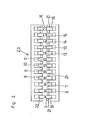
- the device according to FIG. 1 is equipped with a storage part 1, in which twelve reels for reinforcing wires 5 to 16, each of which has a different diameter, are arranged in two rows.
- Each reel is equipped with a conventional balancer arm, not shown or shown, and a spring-loaded brake that is released when the balancer arm is actuated.
- the reels for the reinforcement wires with a diameter from 12 mm, i.e. for the wires 12 - 16, are additionally equipped with a hydraulic driver.
- the selection unit 2 is assigned a feed unit 3, which has a plurality of feed devices 19, 20, each consisting of a drive roller 19 and a pinch roller 20, each of which, individually controlled, can move one of the ends of the reinforcing wires 5 to 16 projecting into the selection unit (Fig. 2,3).
- a cutting unit 17 which consists of the maximum number of rods of the bundle corresponding, individually controlled scissors. The design of these scissors essentially corresponds to that used in the manufacture of lattice girders or structural steel mats, and is therefore not shown in more detail.
- the cutting unit 17 is followed by a welding unit 4 which combines the rods into bundles and ejects them at the end of the device.
- the direction of work corresponds to arrow A.
- the number of reels and thus the reinforcement wires 5-16 in the illustrated embodiment is three times the maximum number of bars to be bundled. Generally it is at least one bigger. This means that more and more reinforcement wires 5 - 16 are available in the selection device 2 than are required for the production of a bundle.
- the number and the diameter of the reinforcing wires 5 to 16 can therefore be selected with the aid of the feed devices 19, 20.
- twelve reinforcement wires 5 to 16 are shown, the ends of which protrude into the selection unit 2.
- a feed device 19, 20 is assigned to each of these reinforcement wires, the drive shafts 21 of the drive rollers 19 being individually drivable.
- the reinforcing wires 5 to 16 are arranged in one plane with increasing diameter, starting from the left in the drawing. Since bars with adjacent diameters are usually bundled, for example to produce a bundle according to FIG. 4, the feed devices are set in motion, between which the reinforcement wires 7, 8, 9 are clamped. If the bundle of staggered bars according to FIG. 6 is to approach the course of the bending moment, the feed device assigned to the reinforcement wire 8 begins with the feed.
- the feed device assigned to the reinforcement wire 7 and finally the feed device assigned to the reinforcement wire 9 are set in motion, all feed devices 19, 20 running at the same speeds, in particular using the cycle method.
- the on this Reinforcement wires reaching the welding unit 4 are welded to one another at least in some places.
- the advance of the reinforcement wire 9 is first stopped and at the same time cut off by a pair of scissors of the cutting unit 17 assigned to it.
- the feed of the wires 7 and 8 is continued, as is the welding.
- the feed of the wire 7 is stopped as soon as its pre-calculated length is reached and another pair of scissors assigned to it cuts it off.
- the feed of the wire 8 is continued up to the total length of the bundle, missing welds being carried out.
- the reinforcement wire 8 is also cut by a further, individually controlled pair of scissors and the finished bundle is ejected from the device.
- the procedure for producing a bundle according to FIG. 5 is the same, except that a total of four reinforcement wires 7, 8, 9, 10 are processed.
- This version is also suitable for bundling non-adjacent reinforcement wires, since any feed device can be set in motion by the individual control.
- the feed unit shown in FIG. 3 shows three feed devices 19, 20, which are combined in two feed blocks 22.
- This feed unit can be used for production systems in which only two- or three-bar bundles are to be produced, in which adjacent diameters are used. If the production of four-bar bundles according to FIG. 5 is also provided, each feed block 22 is equipped with four rollers, so that four feed devices 19, 20 can be used.
- the reinforcement wires 5 to 16 are in turn arranged with increasing diameter in the selection unit 2, starting from the left, the common center plane running horizontally.
- the reinforcement wires 5 to 16 are aligned so that they have two common tangential planes, which enclose the angle plate with each other.
- Each feed block 22 is displaceable in the direction of arrow B on a guide track 23 which is height-adjustable in the direction of arrow C, each guide track 23 running parallel to a tangential plane and therefore the angle with the horizontal includes.
- the feed devices 19, 20 therefore each grip a group of adjacent reinforcement wires 5 to 16, and because of the oblique guideways 23, no individual adaptation to the different diameters of the reinforcement wires is necessary.
- the drive rollers 19 of the feed devices can in turn be driven individually, so that any combination of reinforcement wires is again possible within each group.
- the guideways 23 are moved apart, the feed blocks 22 are moved to the desired position and the guideways 23 are brought closer together again, whereupon the feed of the changed group of reinforcement wires can be started in the manner described for FIG. 2.
- the method according to the invention enables, by means of a relatively simple device, the automatic production of reinforcement bundles in a large number of different combinations of bars, lengths and diameters without time-consuming changes the system are necessary.
- the system is advantageously controlled by means of electronic data processing, by means of which the reinforcement wires are automatically selected, the feed devices assigned to these selected wires are used, and the shears of the cutting unit assigned to the selected wires are used.
- the preferred embodiment of the invention in which only reinforcement wires with different diameters are used, provides a further advantage of great importance.
- about a third of the total reinforcement runs up to the support, since the reinforcement wire 8 with the middle cross section is the longest. If a higher proportion is required, wire 9 becomes necessary; if a lower proportion is required, wire 7 is provided in its entire length and the others are shortened.
Abstract
Description
Die Erfindung bezieht sich auf ein Verfahren zur Herstellung eines Bewehrungsbündels, das aus mindestens zwei zueinander parallelen Bewehrungsstäben besteht, die einander über die gesamte Länge berühren, und eine Vorrichtung zu dessen Durchführung.The invention relates to a method for producing a reinforcement bundle, which consists of at least two mutually parallel reinforcement bars that touch each other over the entire length, and a device for carrying it out.
Es ist bekannt, Bewehrungsstäbe durch Bündel von zumindest drei gleich langen dünneren, einander berührenden Bewehrungsstäben zu ersetzen (AT-PS 230 074), wobei eine Verbindung der Stäbe zumindest an einigen Stellen vorgesehen ist. Die Aufteilung des Einzelstabes in verschweißte Bündel aus gleich langen Stäben bringt verschiedene Vorteile mit sich: Oberflächenvergrößerung, Knickfestigkeitserhöhung, günstigeres Trägheits- und Widerstandsmoment, Beschränkung auf wenige Durchmesser, sowie, beim Ersatz von Stäben mit großen Durchmessern, auch geringere Gestehungskosten, da diese gegenüber mehreren Stäben des mittleren Durchmesserbereiches beträchtliche Preiszuschläge aufweisen. Der letztgenannte Vorteil tritt bei Bewehrungsstäben mit hoher Stahlqüalität besonders in Erscheinung. Die Bewehrungsstäbe können - je nach zu erzielendem Gesamtquerschnitt oder nach den zur Verfügung stehenden Stäben - gleiche oder unterschiedliche Durchmesser aufweisen.It is known to replace reinforcing bars with bundles of at least three equally long, thinner, contacting reinforcing bars (AT-PS 230 074), a connection of the bars being provided at least in some places. The division of the individual rod into welded bundles of rods of the same length has various advantages: surface enlargement, increased resistance to buckling, more favorable moment of inertia and resistance, limitation to a few diameters, and, when replacing rods with large diameters, also lower production costs, since these cost more than several Bars in the medium diameter range have considerable price surcharges. The latter advantage is particularly evident in reinforcement bars with high steel quality. The Reinforcing bars can have the same or different diameters, depending on the overall cross-section to be achieved or the bars available.
Es ist weiters bekannt (NL-PS 67478), Bewehrungsbündel dieser Art in Anpassung an den Momentenverlauf herzustellen, in dem die Enden der Stäbe in der Länge abgestuft sind. Es ist weiters bekannt (DE-OS 25 18 133), ein derartiges Bündel aus Stäben gleicher Länge zu erzeugen, die gegeneinander verschoben sind.It is also known (NL-PS 67478) to produce reinforcement bundles of this type in line with the torque curve in which the ends of the bars are stepped in length. It is also known (DE-OS 25 18 133) to produce such a bundle of rods of the same length, which are shifted against each other.
In keiner der vorgenannten Druckschriften ist ein Herstellungsverfahren für derartige Bewehrungsbündel aus mindestens zwei, vorzugsweise drei oder vier Bewehrungsstäben, in einer automatischen Fertigungsanlage beschrieben, wofür folgende Gründe maßgeblich sind:
- In üblichen automatischen Fertigungsanlagen für Gitterträger, Baustahlmatten, usw. werden alle zur Verarbeitung vorgesehenen, im allgemeinen auf Haspeln angeordneten Bewehrungsdrähte in die Fertigungsanlage eingeführt und auch verarbeitet. Die Fertigungsanlagen sind für eine, gegebenenfalls auch umstellbar für andere Ausführungen der zu erzeugenden Bewehrungselemente vorgesehen, wobei die Umstellung, bedingt durch Wechsel der Haspel, Veränderung der Drahtabstände, Schweißzeitabstände, usw. verhältnismäßig lange Stillstandszeiten der Fertigungsanlage bedingt.
- In conventional automatic production systems for lattice girders, structural steel mats, etc., all reinforcement wires intended for processing, generally arranged on reels, are introduced into the production system and also processed. The production plants are provided for one, possibly also convertible for other designs of the reinforcement elements to be produced, the conversion, due to changing the reel, changing the wire spacing, welding time spacing, etc., resulting in relatively long downtimes of the production plant.
Die Bündelung von Bewehrungsstäben ist vor allem für den Ersatz von Einzelstäben größeren Durchmessers, etwa ab einem Durchmesser von 18 mm günstig, wobei die Bündelung von zwei, drei oder vier Stäben besondere Vorteile bringt. Da die Durchmesserstaffelung im allgemeinen 1 mm, bei größeren Durchmessern 2 mm beträgt, sind also eine große Anzahl von Einzelstäben größeren Durchmessers durch Bewehrungsbündel zu ersetzen.The bundling of reinforcing bars is particularly favorable for the replacement of single bars of larger diameter, for example from a diameter of 18 mm, whereby the bundling of two, three or four bars brings particular advantages. Since the diameter graduation is generally 1 mm, for
Der Bedarf an Einzelstäben größerer Durchmesser ist jedoch nicht in einem derartig großen Ausmaß gegeben,.daß herkömmliche Fertigungsanlagen nach entsprechender Änderung rationell eingesetzt werden können, da sowohl die zu häufige Umstellung zur Erzeugung der großen Anzahl verschiedener Bewehrungsbündel unwirtschaftlich ist als auch der Einsatz mehrerer Fertigungsanlagen mangels Auslastung unwirtschaftlich ist.However, the need for single bars of larger diameter is not so great that conventional manufacturing plants can be used rationally after a corresponding change, since both the too frequent changeover to produce the large number of different reinforcement bundles is uneconomical and the use of several manufacturing plants is deficient Utilization is uneconomical.
Es werden daher, wie beispielsweise in der DE-OS 25 18 133 erwähnt, gerade Stabstücke der benötigten Längen und Durchmesser einzeln gebündelt, um wenigstens bei deren Verlegung Arbeitszeit einzusparen.Therefore, as mentioned for example in DE-OS 25 18 133, straight rod pieces of the required lengths and diameters are bundled individually in order to save working time at least when they are being laid.
Die Erfindung hat es sich nun zur Aufgabe gestellt, ein Verfahren zu schaffen, das mittels einer einfachen, rationell einsetzbaren Vorrichtung zur Herstellung von Bewehrungsbündeln beliebiger Stabanzahl und be-' liebiger Durchmesser geeignet ist, wobei in bevorzugten Ausführungen die Durchmesser der Stäbe auch innerhalb des Bündels unterschiedlich sind.und deren Längen an den Verlauf der Biegemomentenlinie angepaßt werden können. Es sollen also insbesondere Bündel aus zwei, drei oder vier Stäben gleichen und unterschiedlichen Durchmessers und gleicher oder unterschiedlicher Länge in einer einzigen automatischen Fertigungsanlage ohne wesentliche Stillstandszeiten gefertigt werden können, wobei die Gesamtanlage, insbesondere die Anzahl von Haspeln sich in einem wirtschaftlich vertretbaren, dem Bedarf an Bewehrungsbündeln etwa angepaßten Ausmaß bewegt.The invention has now set itself the task of creating a method which is suitable by means of a simple, rationally usable device for producing reinforcement bundles of any number of bars and any diameter, in preferred embodiments the diameter of the bars also within the bundle are different. and their lengths can be adapted to the course of the bending moment line. In particular, bundles of two, three or four bars of the same and different diameters and the same or different lengths should be able to be produced in a single automatic production system without significant downtimes, the overall system, in particular the number of reels, being economically justifiable on the reinforcement bundles moved about adjusted extent.
Erfindungsgemäß wird diese Aufgabe dadurch gelöst, daß aus einer Anzahl von auf Haspeln gewickelten Bewehrungsdrähten, die zumindest um eins größer ist als die Zahl der Stäbe im herzustellenden Bewehrungsbündel, eine der Stabanzahl im Bündel entsprechende Anzahl von Bewehrungsdrähten ausgewählt wird, durch Vorschubeinrichtungen erfaßt, einer Schweißeinrichtung zugeführt, miteinander an zumindest einigen Stellen verschweißt und auf die gewünschte Länge zugeschnitten werden.According to the invention, this object is achieved in that from a number of reinforcement wires wound on reels, which is at least one larger than the number of bars in the bundle of reinforcements to be produced, a number of reinforcement wires corresponding to the number of bars in the bundle is selected by feed devices, a welding device fed, welded together at least some places and cut to the desired length.
Eine hiezu geeignete Vorrichtung ist gekennzeichnet durch einen Vorratsteil mit auf Haspeln gewickelten Bewehrungsdrähten und mit diesen zugeordneten Richteinrichtungen, durch eine Auswahleinheit, durch eine Vorschubeinheit mit gesteuert selektierenden Vorschubeinrichtungen, durch eine unmittelbar anschließende Schneideeinheit und durch eine Verschweißungseinheit, wobei die Zahl der Haspeln um mindestens eins größer ist als die Zahl der Bewehrungsstäbe des Bündels und wobei die Enden aller Bewehrungsdrähte ständig in die Auswahleinheit ragen, in der die ausgewählten Bewehrungsdrähte von den Vorschubeinrichtungen erfaßbar sind, wobei bevorzugt jede Vorschubeinrichtung aus einer Treibrolle und einer Klemmrolle besteht, wobei jede Treibrolle auf einer eigenen, antreibbaren Antriebswelle angeordnet.ist.A device suitable for this purpose is characterized by a supply part with reinforcement wires wound on reels and with straightening devices assigned to them, by a selection unit, by a feed unit with controlled selectable feed devices, by an immediately adjoining cutting unit and by a welding unit, the number of reels being at least one is greater than the number of reinforcing bars of the bundle and the ends of all reinforcing wires constantly protrude into the selection unit in which the selected reinforcing wires can be grasped by the feed devices, each feed device preferably consisting of a drive roller and a pinch roller, each drive roller on its own , drivable drive shaft is arranged.
Nach dem erfindungsgemäßen Vorschlag stehen also in der Vorrichtung ständig alle Bewehrungsdrähte zur Verfügung, von denen nur diejenigen ausgesucht und bearbeitet werden, die für das gerade herzustellende Bewehrungsbündel benötigt werden. Werden beispielsweise zweistäbige Bewehrungsbündel benötigt, können von vier in die Auswahleinrichtung eingeführten Bewehrungsdrähten zwei erfaßt und miteinander verschweißt werden. Die Umstellung auf die Erzeugung dreistäbiger Bündel beschränkt sich daher auf die Aktivierung eines weiteren vorhandenen Bewehrungsdrahtes, der in den Verarbeitungsprozeß eingegliedert wird. Zur Herstellung eines vierstäbigen Bündels wird auch der vierte, in der Auswahleinrichtung ruhende Bewehrungsstab in die Fertigung eingeschlossen.According to the proposal according to the invention, all reinforcement wires are therefore constantly available in the device, of which only those are selected and processed which are required for the reinforcement bundle to be produced. If, for example, two-bar reinforcement bundles are required, Two of four reinforcement wires inserted into the selection device can be gripped and welded together. The changeover to the production of three-bar bundles is therefore limited to the activation of an additional existing reinforcement wire, which is integrated into the processing process. In order to produce a four-bar bundle, the fourth reinforcing bar resting in the selection device is also included in the production.
Eine Vorrichtung mit vier Bewehrungsdrähten gleicher Dicke ist daher bereits in der Lage, drei verschiedene Arten von Bündeln mit gleich langen Stäben in beliebigen Längen zu erzeugen. Sollen die Bewehrungsbündel an den Momentenverlauf angenähert werden, sodaß also die Längen der Bewehrungsstäbe gestaffelt sind, so kann dies dadurch erreicht werden, daß die ausgewählten Bewehrungsdrähte von den einzeln steuerbaren Vorschubeinrichtungen zeitlich versetzt der Schweißeinrichtung mit gleicher Vorschubgeschwindigkeit zugeführt werden und daß der Vorschub der ausgewählten Bewehrungsdrähte in umgekehrter Reihenfolge zeitlich versetzt unterbrochen wird, wobei jeder Bewehrungsdraht unmittelbar nach der Unterbrechung seines Vorschubs abgeschnitten wird.A device with four reinforcement wires of the same thickness is therefore already able to produce three different types of bundles with bars of the same length in any length. If the reinforcement bundles are to be approximated to the torque curve, so that the lengths of the reinforcement bars are staggered, this can be achieved in that the selected reinforcement wires are fed from the individually controllable feed devices to the welding device at the same feed rate and the feed of the selected reinforcement wires is interrupted in reverse order in time, each reinforcement wire being cut off immediately after the interruption of its feed.
Gegenüber der zuvor erwähnten Vorrichtung ist zur Durchführung dieses Verfahrens ergänzend vorgesehen, daß die Schneideeinheit eine der maximalen Anzahl der Bewehrungsstäbe des Bewehrungsbündels entsprechende Zahl von Schneideeinrichtungen aufweist, die einzeln gesteuert betätigbar sind.Compared to the aforementioned device, it is additionally provided for carrying out this method that the cutting unit has a number of cutting devices which corresponds to the maximum number of reinforcing bars of the reinforcement bundle and which can be actuated individually in a controlled manner.
Dieselbe Vorrichtung, ergänzt um getrennt steuerbare Schneideeinrichtungen, ist daher in der Lage, zwei-, drei- oder vierstäbige Bündel in beliebigen Längen zu erzeugen, wobei von Bündel zu Bündel die Stablängen an den Momentenverlauf angepaßt und daher unterschiedlich sind.The same device, supplemented by separately controllable cutting devices, is therefore capable of bundles of two, three or four bars of any length to generate, with the rod lengths adapted to the torque curve from bundle to bundle and therefore different.
Besonders vorteilhaft erweist sich in weiterer Folge, wenn die Bewehrungsstäbe im einzelnen Bündel unterschiedliche Durchmesser aufweisen. Beispielsweise lassen sich mit wiederum nur vier Bewehrungsdrähten in aufeinanderfolgenden Durchmessern drei verschiedene zweistäbige Bündel, zwei verschiedene dreistäbige Bündel und ein vierstäbiges Bündel, insgesamt also sechs verschiedene Arten von Bündeln, jeweils in beliebigen, an den Momentenverlauf angepaßten Längen, herstellen, wenn nur Bewehrungsdrähte mit aufeinanderfolgenden Durchmessern kombiniert werden. Das hiezu geeignete Verfahren sieht erfindungsgemäß vor, daß die auf Haspeln gewickelten Bewehrungsdrähte nach steigendem Durchmesser gereiht den Vorschubeinrichtungen zugeordnet werden, daß aus der Reihe von Bewehrungsdrähten eine der Stabanzahl des Bündels entsprechende Gruppe von nebeneinanderliegenden Bewehrungsdrähten von den Vorschubeinrichtungen erfaßt und der Schweißeinrichtung zugeführt wird, wobei keine wesentliche konstruktive Änderung der zuvor beschriebenen Vorrichtung erforderlich ist. Werden die Durchmesser beliebig kombiniert, so sind sechs verschiedene zweistäbige, vier dreistäbige und ein vierstäbiges, also insgesamt elf verschiedene Bündel herstellbar, jeweils in beliebigen Längen. Der sich daraus ergebende Vorteil wird insbesondere bei einer Erhöhung der Haspelanzahl vervielfacht. Werden beispielsweise zwölf Haspeln vorgesehen, die Bewehrungsdrähte in den gängigen mittleren Durchmessern zwischen fünf und sechzehn Millimetern mit jeweils einem Millimeter Unterschied vorgesehen, können Bewehrungsbündel hergestellt werden, die alle üblichen Einzelstäbe ersetzen können, wobei das Ausmaß des Vorratsteils unter dem von Gitterschweißmaschinen üblicher Breite liegt.Subsequently, it proves to be particularly advantageous if the reinforcement bars have different diameters in the individual bundle. For example, with only four reinforcement wires in successive diameters, three different two-bar bundles, two different three-bar bundles and one four-bar bundle, i.e. a total of six different types of bundles, each in any length adapted to the course of the moment, can be produced if only reinforcement wires with successive diameters Diameters can be combined. The method suitable for this purpose provides, according to the invention, that the reinforcement wires wound on reels are assigned to the feed devices according to increasing diameter, that from the row of reinforcement wires a group of adjacent reinforcement wires corresponding to the number of bars of the bundle is detected by the feed devices and fed to the welding device, whereby no significant design change of the device described above is required. If the diameters are combined as desired, six different two-bar, four three-bar and one four-bar, i.e. a total of eleven different bundles can be produced, each in any length. The resulting advantage is multiplied particularly when the number of reels is increased. If, for example, twelve reels are provided, the reinforcement wires are provided in the common mean diameters between five and sixteen millimeters, each with a difference of one millimeter, reinforcement bundles are produced, which can replace all the usual single rods, the extent of the stock part being less than the usual width of mesh welding machines.
Die Vorschubeinheit kann in einer ersten Ausführung eine der gesamten Zahl der Bewehrungsdrähte entsprechende Zahl von Vorschubeinrichtungen aufweisen, die einzeln gesteuert einsetzbar sind. Es werden also nur jene eingeschaltet, die die gewünschten Bewehrungsdrähte befördern sollen.In a first embodiment, the feed unit can have a number of feed devices corresponding to the total number of reinforcing wires, which can be used individually controlled. So only those are switched on, which should convey the desired reinforcement wires.
Eine weitere Ausführung einer Vorrichtung sieht vor, daß die Vorschubeinheit eine der maximalen Zahl der Bewehrungsstäbe des Bewehrungsbündels entsprechende Zahl von Vorschubeinrichtungen aufweist, wobei alle Treibrollen und alle Klemmrollen jeweils zu einem Vorschubblock zusammengefaßt sind. und beide Vorschubblöcke in einer Ebene senkrecht zur Arbeitsrichtung in zwei Richtungen verschiebbar und Gruppen von ausgewählten Bewehrungsdrähten, die nach steigendem Durchmesser geordnet nebeneinander in die Auswahleinrichtung ragen, zuordenbar sind. Bei dieser Ausführung werden also wesentlich weniger Vorschubeinrichtungen benötigt, die gemeinsam zwischen den einzelnen Vorschubpositionen verstellbar sind. Ist beispielsweise die Herstellung von maximal vierstäbigen Bündeln geplant, werden vier Vorschubeinrichtungen im Vorschubblock vorgesehen, wobei jede wiederum vorzugsweise einzeln antreibbar ist, um auch zwei- und dreistäbige Bündel erzeugen zu können.A further embodiment of a device provides that the feed unit has a number of feed devices corresponding to the maximum number of reinforcement bars of the reinforcement bundle, all drive rollers and all pinch rollers being combined to form a feed block. and both feed blocks can be displaced in two directions in a plane perpendicular to the working direction and groups of selected reinforcing wires, which project into the selection device next to one another in an ordered manner according to increasing diameter, can be assigned. In this embodiment, significantly fewer feed devices are required, which can be adjusted jointly between the individual feed positions. If, for example, the production of a maximum of four-bar bundles is planned, four feed devices are provided in the feed block, each of which in turn can preferably be driven individually in order to also be able to produce two- and three-bar bundles.
Anstelle eines Einzelantriebes der Vorschubeinrichtungen ist es'im übrigen denkbar, einen gemeinsamen Antrieb vorzusehen, wobei jedoch nur die benötigten Vorschubeinrichtungen an den Bewehrungsdrähten angreifen und die übrigen beispielsweise geöffnet gehalten werden. Werden die Rollen der Vorschubeinrichtungen federnd gelagert, können die Vorschubblöcke parallel zueinander verschoben werden, wobei die unterschiedlichen Durchmesser der Bewehrungsdrähte durch verschieden starke Kompression der Federn ausgeglichen werden.Instead of a single drive of the feed devices, it is also conceivable to have a common one Provide drive, but only the required feed devices attack the reinforcement wires and the others are kept open, for example. If the rollers of the feed devices are spring-mounted, the feed blocks can be moved parallel to one another, the different diameters of the reinforcement wires being compensated for by different compression of the springs.
In einer anderen Ausführung ist vorgesehen, daß die Enden der Bewehrungsdrähte zwei gemeinsame Tangentialebenen aufweisen, die einen Winkel einschließen und jeder Vorschubblock parallel zu einer Tangentialebene verschiebbar ist. Wenn die Mittelebene aller Bewehrungsdrähte horizontal verläuft, schließen die Verschiebe-_ bahnen der Vorschubblöcke zur Horizontalen jeweils den halben Winkel der beiden Tangentialebenen ein.In another embodiment it is provided that the ends of the reinforcement wires have two common tangential planes which enclose an angle and each feed block can be displaced parallel to a tangential plane. If the center plane of all reinforcement wires runs horizontally, the displacement paths of the feed blocks to the horizontal each include half the angle of the two tangential planes.
Nachstehend wird nun die Erfindung an Hand der Figuren der beiliegenden Zeichnungen näher beschrieben, ohne darauf beschränkt zu sein.The invention will now be described in more detail below with reference to the figures in the accompanying drawings, without being limited thereto.
Es zeigen:
- Fig. 1 schematisch eine Draufsicht auf eine erfindungsgemäße Vorrichtung,
- Fig. 2 und 3 Schnitte nach der Linie II-II bzw. III-III der Fig. 1,
- Fig. 4 und 5 Stirnansichten erfindungsgemäßer Bewehrungsbündel,und
- Fig. 6 eine Endansicht eines Bewehrungsbündels.
- 1 schematically shows a top view of a device according to the invention,
- 2 and 3 sections along the line II-II and III-III of Fig. 1,
- 4 and 5 end views of reinforcement bundles according to the invention, and
- Fig. 6 is an end view of a reinforcement bundle.
Die Vorrichtung gemäß Fig. 1 ist mit einem Vorratsteil 1 ausgestattet, in dem zwölf Haspeln für Bewehrungsdrähte 5 bis 16, von denen jeder einen anderen Durchmesser aufweist, in zwei Reihen angeordnet sind. Die Bewehrungsdrähte 5 bis 16 weisen beispielsweise jeweils um 1 mm unterschiedliche Durchmesser auf, von 5 mm steigend, und entsprechen den gängigen, auf Haspeln wickelbaren Bewehrungsdrähten. Jede Haspel ist mit einer nicht näher bezeichneten bzw. dargestellten, üblichen Ausgleichsschwinge und einer federbelasteten Bremse ausgestattet, die beim Betätigen der Ausgleichsschwinge gelüftet wird. Die Haspeln für die Bewehrungsdrähte mit einem Durchmesser ab 12 mm, also für die Drähte 12 - 16, sind zusätzlich mit einem hydraulischen Treiber versehen. Vor jeder Haspel ist der Bewehrungsdraht 5 bis 16 durch eine separate Richteinrichtung 18 zur Auswahleinheit 2 geführt, in die die Enden der Bewehrungsdrähte 5 bis 16 ragen. Der Auswahleinheit 2 ist eine Vorschubeinheit 3 zugeordnet, die mehrere Vorschubeinrichtungen 19,20, jeweils aus einer Treibrolle 19 und einer Klemmrolle 20 bestehend, aufweist, von denen jede, einzeln gesteuert, eines der in die Auswahleinheit ragenden Enden der Bewehrungsdrähte 5 bis 16 weiterbewegen kann (Fig. 2,3). Unmittelbar nach der Vorschubeinheit 3 folgt eine Schneideeinheit 17, die aus der maximalen Anzahl der Stäbe des Bündels entsprechenden, einzeln gesteuerten Scheren besteht. Die Ausbildung dieser Scheren entspricht im wesentlichen der bei der Gitterträger-oder Baustahlmattenherstellung verwendeten, und ist daher nicht näher gezeigt. Im Anschluß an die Schneideeinheit 17 folgt eine Verschweißungseinheit 4, die die Stäbe zu Bündeln vereinigt und am Ende der Vorrichtung ausstößt. Die Arbeitsrichtung entspricht also dem Pfeil A.The device according to FIG. 1 is equipped with a storage part 1, in which twelve reels for reinforcing
Die Zahl der Haspeln und damit der Bewehrungsdrähte 5 - 16 beträgt im dargestellten Ausführungsbeispiel das Dreifache der maximal zu bündelnden Stäbe. Allgemein ist sie um zumindest eins größer. Dies bedeutet, daß in der Auswahleinrichtung 2 immer mehr Bewehrungsdrähte 5 - 16 zur Verfügung stehen als für die Herstellung eines Bündels benötigt werden.The number of reels and thus the reinforcement wires 5-16 in the illustrated embodiment is three times the maximum number of bars to be bundled. Generally it is at least one bigger. This means that more and more reinforcement wires 5 - 16 are available in the
Es können daher mit Hilfe der Vorschubeinrichtungen 19,20 die Zahl und die Durchmesser der Bewehrungsdrähte 5 bis 16 ausgewählt werden.The number and the diameter of the reinforcing
In der in Fig. 2 gezeigten Ausführung sind zwölf Bewehrungsdrähte 5 bis 16 gezeigt, deren Enden in die Auswahleinheit 2 ragen. Jedem dieser Bewehrungsdrähte ist eine Vorschubeinrichtung 19,20 zugeordnet, wobei die Antriebswellen 21 der Treibrollen 19 einzeln antreibbar sind. Die Bewehrungsdrähte 5 bis 16 sind - in der Zeichnung von links beginnend - mit steigendem Durchmesser in einer Ebene angeordnet. Da überlicherweise Stäbe mit benachbarten Durchmessern gebündelt werden, werden beispielsweise zur Erzeugung eines Bündels gemäß Fig. 4 die Vorschubeinrichtungen in Bewegung gesetzt, zwischen denen die Bewehrungsdrähte 7,8,9 eingespannt sind. Soll das Bündel gestaffelte Stäbe gemäß Fig. 6 zur Annäherung an den Biegemomentenverlauf aufweisen, beginnt zuerst die dem Bewehrungsdraht 8 zugeordnete Vorschubeinrichtung mit dem Vorschub. Nach den berechneten zeitlichen Abständen wird die dem Bewehrungsdraht 7 zugeordnete Vorschubeinrichtung und schließlich die dem Bewehrungsdraht 9 zugeordnete Vorschubeinrichtung in Bewegung gesetzt, wobei alle Vorschubeinrichtungen 19,20 mit denselben Geschwindigkeiten, insbesondere im Taktverfahren, laufen. Die auf diese Weise zur Verschweißungseinheit 4 gelangenden Bewehrungsdrähte werden zumindest an einigen Stellen untereinander verschweißt. Entsprechend der vorberechneten Länge wird zuerst der Vorschub des Bewehrungsdrahtes 9 gestoppt und gleichzeitig durch eine diesem zugeordnete Schere der Schneideinheit 17 abgetrennt. Der Vorschub der Drähte 7 und 8 wird fortgesetzt, ebenso die Verschweißung. In weiterer Folge wird der Vorschub des Drahtes 7 gestoppt, sobald dessen vorberechnete Länge erreicht ist und eine weitere diesem zugeordnete Schere schneidet ihn ab. Der Vorschub des Drahtes 8 wird bis zur Gesamtlänge des Bündels fortgesetzt, wobei noch fehlende Schweißstellen ausgeführt werden. Schließlich wird auch durch eine weitere, einzeln gesteuerte Schere der Bewehrungsdraht 8 geschnitten und das fertiggestellte Bündel aus der Vorrichtung ausgestoßen.In the embodiment shown in FIG. 2, twelve
Zur Herstellung eines Bündels gemäß Fig. 5 wird in gleicher Weise verfahren, wobei jedoch insgesamt vier Bewehrungsdrähte 7,8,9,10 bearbeitet werden. Diese Ausführung eignet sich auch zur Bündelung von nicht benachbarten Bewehrungsdrähten, da durch die Einzelsteuerung jede beliebige Vorschubeinrichtung in Bewegung gesetzt werden kann.The procedure for producing a bundle according to FIG. 5 is the same, except that a total of four
Die in Fig. 3 dargestellte Vorschubeinheit zeigt drei Vorschubeinrichtungen 19,20, die in zwei Vorschubblöcken 22 zusammengefaßt sind. Diese Vorschubeinheit kann für Fertigungsanlagen Verwendung finden, in denen ausschließlich zwei- oder dreistäbige Bündel erzeugt werden sollen, in denen benachbarte Durchmesser eingesetzt werden. Wenn auch die Erzeugung vierstäbiger Bündel gemäß Fig. 5 vorgesehen ist, wird jeder Vorschubblock 22 mit vier Rollen bestückt, sodaß vier Vorschubeinrichtungen 19,20 einsetzbar sind.The feed unit shown in FIG. 3 shows three
Die Bewehrungsdrähte 5 bis 16 sind wiederum mit - von links beginnend - steigendem Durchmesser in der Auswahleinheit 2 angeordnet, wobei die gemeinsame Mittelebene horizontal verläuft. Die Bewehrungsdrähte 5 bis 16 sind dabei so ausgerichtet, daß sie zwei gemeinsame Tangentialebenen aufweisen, die untereinander den Winkeldl einschließen. Jeder Vorschubblock 22 ist auf einer in Richtung des Pfeiles C höhenverstellbaren Führungsbahn 23 in Richtung des Pfeiles B verschiebbar, wobei jede Führungsbahn 23 parallel zu einer Tangentialebene verläuft und daher mit der Horizontalen den Winkel ![]()
![]()
Das erfindungsgemäße Verfahren ermöglicht mittels einer relativ einfachen Vorrichtung die automatische Herstellung von Bewehrungsbündeln in einer Vielzahl von verschiedenen Stabanzahl-, Stablängen- und Stabdurchmesserkombinationen, ohne daß zeitraubende Umstellungen der Anlage notwendig sind. Die Steuerung der Anlage erfolgt vorteilhaft mittels elektronischer Datenverarbeitung, durch die automatisch die Auswahl der Bewehrungsdrähte, der Einsatz der diesen ausgewählten Drähten zugeordneten Vorschubeinrichtungen und der Einsatz der den ausgewählten Drähten zugeordneten Scheren der Schneideinheit erfolgt.The method according to the invention enables, by means of a relatively simple device, the automatic production of reinforcement bundles in a large number of different combinations of bars, lengths and diameters without time-consuming changes the system are necessary. The system is advantageously controlled by means of electronic data processing, by means of which the reinforcement wires are automatically selected, the feed devices assigned to these selected wires are used, and the shears of the cutting unit assigned to the selected wires are used.
Vor allem die bevorzugte Ausführung der Erfindung, in der ausschließlich Bewehrungsdrähte mit unterschiedlichen Durchmessern eingesetzt werden, erbringt noch einen weiteren Vorteil von großer Bedeutung. In vielen Staaten existieren unterschiedliche Bestimmungen über den Querschnittsanteil der über die Gesamtlänge durchgehenden Bewehrungsstäbe bei Momentenanpassung. Es kann ebenfalls ohne jede Änderung der Vorrichtung durch entsprechende Steuerung jeder der zu einem Bündel zusammenzufassenden Bewehrungsdrähte über die gesamte Länge vorgesehen werden. Entsprechend dem Beispiel von Fig. 6 verläuft etwa ein Drittel der Gesamtbewehrung bis zur Auflage, da der Bewehrungsdraht 8 mit dem mittleren Querschnitt am längsten ist. Ist ein höherer Anteil erforderlich, wird Draht 9, ist ein niederer Anteil erforderlich, wird Draht 7 in der gesamten Länge vorgesehen und jeweils die anderen werden gekürzt.Above all, the preferred embodiment of the invention, in which only reinforcement wires with different diameters are used, provides a further advantage of great importance. In many countries, there are different provisions regarding the cross-sectional portion of the reinforcement bars that are continuous over the entire length when the torque is adjusted. It can also be provided over the entire length without any modification of the device by appropriate control of each of the reinforcement wires to be combined into a bundle. According to the example of FIG. 6, about a third of the total reinforcement runs up to the support, since the
Claims (9)
Applications Claiming Priority (2)
| Application Number | Priority Date | Filing Date | Title |
|---|---|---|---|
| AT232781A AT382803B (en) | 1981-05-25 | 1981-05-25 | METHOD AND DEVICE FOR PRODUCING A REINFORCEMENT BUNCH |
| AT2327/81 | 1981-05-25 |
Publications (3)
| Publication Number | Publication Date |
|---|---|
| EP0065736A2 true EP0065736A2 (en) | 1982-12-01 |
| EP0065736A3 EP0065736A3 (en) | 1983-08-03 |
| EP0065736B1 EP0065736B1 (en) | 1985-09-25 |
Family
ID=3532297
Family Applications (1)
| Application Number | Title | Priority Date | Filing Date |
|---|---|---|---|
| EP19820104307 Expired EP0065736B1 (en) | 1981-05-25 | 1982-05-17 | Method and apparatus for making a reinforcing bundle |
Country Status (3)
| Country | Link |
|---|---|
| EP (1) | EP0065736B1 (en) |
| AT (1) | AT382803B (en) |
| DE (1) | DE3266500D1 (en) |
Cited By (3)
| Publication number | Priority date | Publication date | Assignee | Title |
|---|---|---|---|---|
| WO2015149088A1 (en) * | 2014-04-01 | 2015-10-08 | Evg Entwicklungs- U. Verwertungs-Gesellschaft M.B.H. | Advancing and straightening device |
| US20170349645A1 (en) * | 2015-01-01 | 2017-12-07 | Navya Biologicals Pvt Ltd. | Novel method for efficient purification of human serum albumin |
| IT202000023467A1 (en) * | 2020-10-06 | 2022-04-06 | M E P Macch Elettroniche Piegatrici Spa | GROUP AND RELATIVE TOWING METHOD FOR METALLIC PRODUCTS |
Families Citing this family (1)
| Publication number | Priority date | Publication date | Assignee | Title |
|---|---|---|---|---|
| AT404566B (en) * | 1993-07-23 | 1998-12-28 | Filzmoser Maschinenbau Ges M B | Straightening and cutting machine for processing concrete reinforcing steel |
Citations (4)
| Publication number | Priority date | Publication date | Assignee | Title |
|---|---|---|---|---|
| DE1113740B (en) * | 1958-05-22 | 1961-09-14 | Standard Elektrik Lorenz Ag | Device for the production of cable harnesses |
| AT230074B (en) * | 1958-11-05 | 1963-11-11 | Hufnagl Walter | Reinforcement arrangement for the reinforcement of reinforced concrete |
| US3119536A (en) * | 1961-05-16 | 1964-01-28 | Berkeley Davis Inc | Wire feeding apparatus |
| US4192207A (en) * | 1977-01-17 | 1980-03-11 | Amp Incorporated | Method for feeding a plurality of wires |
-
1981
- 1981-05-25 AT AT232781A patent/AT382803B/en not_active IP Right Cessation
-
1982
- 1982-05-17 EP EP19820104307 patent/EP0065736B1/en not_active Expired
- 1982-05-17 DE DE8282104307T patent/DE3266500D1/en not_active Expired
Patent Citations (4)
| Publication number | Priority date | Publication date | Assignee | Title |
|---|---|---|---|---|
| DE1113740B (en) * | 1958-05-22 | 1961-09-14 | Standard Elektrik Lorenz Ag | Device for the production of cable harnesses |
| AT230074B (en) * | 1958-11-05 | 1963-11-11 | Hufnagl Walter | Reinforcement arrangement for the reinforcement of reinforced concrete |
| US3119536A (en) * | 1961-05-16 | 1964-01-28 | Berkeley Davis Inc | Wire feeding apparatus |
| US4192207A (en) * | 1977-01-17 | 1980-03-11 | Amp Incorporated | Method for feeding a plurality of wires |
Cited By (4)
| Publication number | Priority date | Publication date | Assignee | Title |
|---|---|---|---|---|
| WO2015149088A1 (en) * | 2014-04-01 | 2015-10-08 | Evg Entwicklungs- U. Verwertungs-Gesellschaft M.B.H. | Advancing and straightening device |
| US20170349645A1 (en) * | 2015-01-01 | 2017-12-07 | Navya Biologicals Pvt Ltd. | Novel method for efficient purification of human serum albumin |
| IT202000023467A1 (en) * | 2020-10-06 | 2022-04-06 | M E P Macch Elettroniche Piegatrici Spa | GROUP AND RELATIVE TOWING METHOD FOR METALLIC PRODUCTS |
| WO2022074692A1 (en) * | 2020-10-06 | 2022-04-14 | M.E.P. Macchine Elettroniche Piegatrici S.P.A. | Drawing unit and corresponding method for metal products |
Also Published As
| Publication number | Publication date |
|---|---|
| AT382803B (en) | 1987-04-10 |
| ATA232781A (en) | 1986-09-15 |
| EP0065736B1 (en) | 1985-09-25 |
| DE3266500D1 (en) | 1985-10-31 |
| EP0065736A3 (en) | 1983-08-03 |
Similar Documents
| Publication | Publication Date | Title |
|---|---|---|
| EP1849536B1 (en) | Bending machine for rod-shaped workpieces like wire or tube | |
| AT405621B (en) | SYSTEM FOR CONTINUOUS PRODUCTION OF COMPONENTS | |
| DE4323009C2 (en) | Device for generating the pitch of a spring in a spring wind device | |
| DE3010923A1 (en) | METHOD FOR CONTINUOUSLY PROCESSING STEEL BARS FOR REINFORCED CONCRETE AND DEVICE FOR CARRYING OUT THE METHOD | |
| WO1998035771A1 (en) | Equipment for straightening, strain-hardening and subsequent machining of wire material | |
| EP0241449A1 (en) | Resistance multi-spot welding machine | |
| EP0065736B1 (en) | Method and apparatus for making a reinforcing bundle | |
| AT395386B (en) | METHOD AND SYSTEM FOR PRODUCING TWO-LAYER WELDED GRID BODIES | |
| EP0538232A1 (en) | Method of making wire gratings | |
| EP1371430A2 (en) | Method and apparatus for the manufacturing of a hollow profile | |
| DE10048104B4 (en) | Apparatus for processing reinforcing wires to at least two groups of rods of different lengths for a reinforcement | |
| DE10064888B4 (en) | Method and device for cutting sheet metal blanks | |
| AT382804B (en) | Method and device for manufacturing a reinforcement bundle | |
| EP0981414B1 (en) | Process and plant for manufacturing grates | |
| DE1552135A1 (en) | Process for the production of grid-shaped reinforcements or the like. for reinforced concrete beams and device to carry out this process | |
| EP0094929B1 (en) | Method and cutting apparatus for subdividing into trellis mats a trellis web consisting of longitudinal wires and rectangularly traversing cross wires | |
| AT405796B (en) | METHOD AND SYSTEM FOR THE PRODUCTION OF WIRE GRIDS | |
| EP0216154B1 (en) | Welding machine with longitudinal wire feeding device for wire grilles made of wires in longitudinal and transverse direction | |
| DE2742026C3 (en) | Pipe forming machine | |
| AT406348B (en) | MAT TRANSPORTER | |
| DE2704814C2 (en) | Milling machine for simultaneous face milling of the top and bottom of a strip-shaped cast strand | |
| EP0081618A1 (en) | Method of producing a reinforcing element of parallel longitudinal rods and transverse rods, spaced along the longitudinal ones | |
| DE2535480C2 (en) | Method and device for sorting out short lengths and / or for cutting predetermined lengths from rod material of different lengths | |
| DE2414530B2 (en) | METHOD AND DEVICE FOR MANUFACTURING GRID-LIKE AREA REINFORCEMENT | |
| EP0814922A1 (en) | Installation for cutting off several thread lengths from a skein of thread material |
Legal Events
| Date | Code | Title | Description |
|---|---|---|---|
| PUAI | Public reference made under article 153(3) epc to a published international application that has entered the european phase |
Free format text: ORIGINAL CODE: 0009012 |
|
| AK | Designated contracting states |
Designated state(s): BE CH DE FR GB IT NL |
|
| PUAL | Search report despatched |
Free format text: ORIGINAL CODE: 0009013 |
|
| AK | Designated contracting states |
Designated state(s): BE CH DE FR GB IT LI NL |
|
| 17P | Request for examination filed |
Effective date: 19830722 |
|
| ITF | It: translation for a ep patent filed |
Owner name: BARZANO' E ZANARDO MILANO S.P.A. |
|
| GRAA | (expected) grant |
Free format text: ORIGINAL CODE: 0009210 |
|
| AK | Designated contracting states |
Designated state(s): BE CH DE FR GB IT LI NL |
|
| REF | Corresponds to: |
Ref document number: 3266500 Country of ref document: DE Date of ref document: 19851031 |
|
| ET | Fr: translation filed | ||
| PLBE | No opposition filed within time limit |
Free format text: ORIGINAL CODE: 0009261 |
|
| STAA | Information on the status of an ep patent application or granted ep patent |
Free format text: STATUS: NO OPPOSITION FILED WITHIN TIME LIMIT |
|
| 26N | No opposition filed | ||
| PGFP | Annual fee paid to national office [announced via postgrant information from national office to epo] |
Ref country code: NL Payment date: 19870531 Year of fee payment: 6 |
|
| PG25 | Lapsed in a contracting state [announced via postgrant information from national office to epo] |
Ref country code: GB Effective date: 19880517 |
|
| PG25 | Lapsed in a contracting state [announced via postgrant information from national office to epo] |
Ref country code: NL Effective date: 19881201 |
|
| NLV4 | Nl: lapsed or anulled due to non-payment of the annual fee | ||
| GBPC | Gb: european patent ceased through non-payment of renewal fee | ||
| PGFP | Annual fee paid to national office [announced via postgrant information from national office to epo] |
Ref country code: CH Payment date: 19890508 Year of fee payment: 8 |
|
| ITTA | It: last paid annual fee | ||
| PG25 | Lapsed in a contracting state [announced via postgrant information from national office to epo] |
Ref country code: BE Effective date: 19890531 |
|
| PGFP | Annual fee paid to national office [announced via postgrant information from national office to epo] |
Ref country code: DE Payment date: 19890617 Year of fee payment: 8 |
|
| PG25 | Lapsed in a contracting state [announced via postgrant information from national office to epo] |
Ref country code: FR Free format text: LAPSE BECAUSE OF NON-PAYMENT OF DUE FEES Effective date: 19900131 |
|
| REG | Reference to a national code |
Ref country code: FR Ref legal event code: ST |
|
| PG25 | Lapsed in a contracting state [announced via postgrant information from national office to epo] |
Ref country code: LI Effective date: 19900531 Ref country code: CH Effective date: 19900531 |
|
| REG | Reference to a national code |
Ref country code: CH Ref legal event code: PL |
|
| PG25 | Lapsed in a contracting state [announced via postgrant information from national office to epo] |
Ref country code: DE Effective date: 19910201 |