EP0065645A2 - Process for treating surfaces of cast iron that contains carbon, as well as apparatus for carrying out the process and cylinder consisting of a grey cast iron casting - Google Patents
Process for treating surfaces of cast iron that contains carbon, as well as apparatus for carrying out the process and cylinder consisting of a grey cast iron casting Download PDFInfo
- Publication number
- EP0065645A2 EP0065645A2 EP82103349A EP82103349A EP0065645A2 EP 0065645 A2 EP0065645 A2 EP 0065645A2 EP 82103349 A EP82103349 A EP 82103349A EP 82103349 A EP82103349 A EP 82103349A EP 0065645 A2 EP0065645 A2 EP 0065645A2
- Authority
- EP
- European Patent Office
- Prior art keywords
- workpiece
- station
- cast iron
- plating
- friction
- Prior art date
- Legal status (The legal status is an assumption and is not a legal conclusion. Google has not performed a legal analysis and makes no representation as to the accuracy of the status listed.)
- Granted
Links
Images

Classifications
-
- B—PERFORMING OPERATIONS; TRANSPORTING
- B23—MACHINE TOOLS; METAL-WORKING NOT OTHERWISE PROVIDED FOR
- B23H—WORKING OF METAL BY THE ACTION OF A HIGH CONCENTRATION OF ELECTRIC CURRENT ON A WORKPIECE USING AN ELECTRODE WHICH TAKES THE PLACE OF A TOOL; SUCH WORKING COMBINED WITH OTHER FORMS OF WORKING OF METAL
- B23H5/00—Combined machining
-
- C—CHEMISTRY; METALLURGY
- C25—ELECTROLYTIC OR ELECTROPHORETIC PROCESSES; APPARATUS THEREFOR
- C25F—PROCESSES FOR THE ELECTROLYTIC REMOVAL OF MATERIALS FROM OBJECTS; APPARATUS THEREFOR
- C25F3/00—Electrolytic etching or polishing
- C25F3/02—Etching
- C25F3/06—Etching of iron or steel
-
- C—CHEMISTRY; METALLURGY
- C25—ELECTROLYTIC OR ELECTROPHORETIC PROCESSES; APPARATUS THEREFOR
- C25F—PROCESSES FOR THE ELECTROLYTIC REMOVAL OF MATERIALS FROM OBJECTS; APPARATUS THEREFOR
- C25F7/00—Constructional parts, or assemblies thereof, of cells for electrolytic removal of material from objects; Servicing or operating
-
- F—MECHANICAL ENGINEERING; LIGHTING; HEATING; WEAPONS; BLASTING
- F16—ENGINEERING ELEMENTS AND UNITS; GENERAL MEASURES FOR PRODUCING AND MAINTAINING EFFECTIVE FUNCTIONING OF MACHINES OR INSTALLATIONS; THERMAL INSULATION IN GENERAL
- F16J—PISTONS; CYLINDERS; SEALINGS
- F16J1/00—Pistons; Trunk pistons; Plungers
- F16J1/08—Constructional features providing for lubrication
-
- F—MECHANICAL ENGINEERING; LIGHTING; HEATING; WEAPONS; BLASTING
- F05—INDEXING SCHEMES RELATING TO ENGINES OR PUMPS IN VARIOUS SUBCLASSES OF CLASSES F01-F04
- F05C—INDEXING SCHEME RELATING TO MATERIALS, MATERIAL PROPERTIES OR MATERIAL CHARACTERISTICS FOR MACHINES, ENGINES OR PUMPS OTHER THAN NON-POSITIVE-DISPLACEMENT MACHINES OR ENGINES
- F05C2203/00—Non-metallic inorganic materials
- F05C2203/08—Ceramics; Oxides
- F05C2203/0865—Oxide ceramics
- F05C2203/0882—Carbon, e.g. graphite
-
- Y—GENERAL TAGGING OF NEW TECHNOLOGICAL DEVELOPMENTS; GENERAL TAGGING OF CROSS-SECTIONAL TECHNOLOGIES SPANNING OVER SEVERAL SECTIONS OF THE IPC; TECHNICAL SUBJECTS COVERED BY FORMER USPC CROSS-REFERENCE ART COLLECTIONS [XRACs] AND DIGESTS
- Y10—TECHNICAL SUBJECTS COVERED BY FORMER USPC
- Y10S—TECHNICAL SUBJECTS COVERED BY FORMER USPC CROSS-REFERENCE ART COLLECTIONS [XRACs] AND DIGESTS
- Y10S408/00—Cutting by use of rotating axially moving tool
- Y10S408/709—Reboring piston receiving cylinder
-
- Y—GENERAL TAGGING OF NEW TECHNOLOGICAL DEVELOPMENTS; GENERAL TAGGING OF CROSS-SECTIONAL TECHNOLOGIES SPANNING OVER SEVERAL SECTIONS OF THE IPC; TECHNICAL SUBJECTS COVERED BY FORMER USPC CROSS-REFERENCE ART COLLECTIONS [XRACs] AND DIGESTS
- Y10—TECHNICAL SUBJECTS COVERED BY FORMER USPC
- Y10T—TECHNICAL SUBJECTS COVERED BY FORMER US CLASSIFICATION
- Y10T408/00—Cutting by use of rotating axially moving tool
- Y10T408/36—Machine including plural tools
- Y10T408/375—Coaxial tools
- Y10T408/378—Coaxial, opposed tools
- Y10T408/3792—Coaxial, opposed tools with means to sequentially feed tools toward work
Definitions
- the invention relates to a method for machining surfaces of a workpiece made of carbon-containing cast iron according to the preamble of claim 1.
- the invention further relates to an apparatus for performing the method.
- the structure of the surface is of particular importance for the tribological conditions in sliding pairings.
- the surface structure of the gray cast iron is of crucial importance for low wear, minimizing friction, running-in behavior and gas tightness of the piston rings.
- oil management which is important for minimizing wear of the sliding partners running in the mixed friction area, so-called oil pockets with cut graphite lamellae and / or mechanically machined grooves must be available on gray cast iron surfaces.
- a sufficiently fine surface roughness (micro-roughness) must be provided to minimize friction.
- the geometry of the surface must have a sufficiently aggressive shape in order to optimize the running-in behavior, so that a mutual processing of the sliding partners is possible during running-in. In the case of the sliding pairing cylinder wall / piston ring, this results in good gas tightness in connection with good roundness. In addition, excessive surface hardening should be avoided so that the piston rings in particular are protected from inadmissible adhesive and / or abrasive wear.
- the invention has the object of providing a method for processing surfaces of a workpiece of carbon cast iron and an apparatus provide for its implementation, with 'the or to achieve a particularly suitable for the tribological conditions in bearings surface structure of carbon cast iron in an economical manner leaves.
- Another object of the invention is to create a cylinder for a piston internal combustion engine with improved operating properties.
- Friction plating is therefore not in the actual sense a machining that removes the material, but rather a rubbing with simultaneous plating, whereby a substantial part of the abraded material is plated and thereby a surface is obtained in which load-bearing, flat plateaus that partly plated with graphite, mixed crystals and / or any electrolysis residues, alternate with open graphite fins.
- a surface produced according to the invention has a dark, shiny appearance.
- the number of alternating electrochemical removal and friction plating steps is appropriately based on the respective requirements. It is a complex combination tool not necessary to carry out the method according to the invention. Rather, tools known per se for electrochemical removal and mechanical processing can be used in their construction.
- electrochemical removal and mechanical processing expediently use different liquids which best meet the respective requirements.
- liquids known per se can be used, which ensure the least possible surface hardening.
- a single liquid, for example NaNO 3 can also be used, which simplifies the implementation of the method.
- the wear resistance of the surface of the workpiece can be increased.
- the hardening can be carried out by a variety of methods known per se, e.g. Remelt hardening, inductive hardening, electroerosive hardening etc.
- Claim 7 characterizes the basic structure of the device suitable for carrying out the method according to the invention.
- the device is expediently designed with the features of claim 8.
- the device according to the invention can be equipped with an electrical station and a mechanical station, between which the workpiece is transported back and forth.
- the device can also be designed with the features of claim 9, the individual stations being matched to the work processes taking place therein
- Claim 11 characterizes one for machining large bores, e.g. Cylinder liners for large diesel engines, particularly advantageous embodiment of the device according to the invention.
- the claim .12 identifies a cylinder with a tread, which is advantageously produced by the method according to the invention.
- This tread surprisingly has excellent running-in properties and a long service life, although the geometry of its surface is in no way aggressive.
- the good properties of the tread which could also be formed by rolling machining, are probably due to the flake-like graphite and / or the M23C6 mixed crystals as well as any other clad residues that the friction partner, in the present example the piston ring or rings, act as a lapping agent.
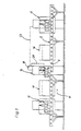
- a device for machining a workpiece made of carbon-containing cast iron, for example mechanically in a known manner to a roughness of about 20 ⁇ m pre-machined cylinder running surfaces of an engine block cast together with the cylinder head is formed by rollers 6 arranged one behind the other.
- rollers 6 arranged one behind the other.
- transport device 8 on.
- the drive of the rollers 6 is not shown in detail, since the structure of the transport device 8 can be of a type known per se.
- alternating reflection stations 12 and mechanical stations 14 are arranged, one of which is shown.
- the passage of the workpiece, not shown in detail, through the cutout of the device shown is such that, according to FIG. workpiece entering from the left into the electrical station 12 th. and there elect in the manner described later. is processed.
- electrochemical processing brings the workpiece from the electrical station 12 to the cleaning station, removes electrolyte residues there and then conveys it to the mechanical station 14. There it becomes mechanical, after which it is moved to the next cleaning station 16 where it is freed of any residues of cutting oils or emulsions, whereupon it is in turn fed to the next electrical station 12.
- FIG. 1 also shows a control unit 18 belonging to the mechanical station 14, in which the diameter of a hole formed in the workpiece is determined in a manner known per se, for example using the dynamic pressure method.
- the measured value is fed to the control unit 18 via a measuring line 20.
- the current intensity and the machining time of the workpiece during subsequent electrochemical removal in the electrical station 12 are determined in the control unit 18, the electrical station 12 being controlled via a control line 22.
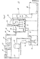
- an electrolyte reservoir 40 is provided, which is connected via a line 42 to a pump 44 which conveys electrolyte into a line 46.
- the line 46 continues within the processing container 24 in a hose 48 which is connected to the hollow electrode holder 50.
- the electrolyte emerging from the electrode 32 and flowing out of the respectively machined bore 30 reaches a return line 52 which opens into an intermediate container 54.
- the electrolyte is conveyed from the intermediate container 54 into a centrifuge 60 by means of a submersible pump 56, which serves to clean the electrolyte. From the centrifuge 60, the electrolyte returns through a line 62 into the electrolyte reservoir 40.
- a styrene supply is provided by a power supply device 64, the positive pole of which is connected to the workpiece 28 via a cable 66 and the negative pole of which is connected to the electrode 32 via a cable 68.
- Electrode 32 which is electrically insulated from hydraulic cylinder 34, is inserted into bore 30 to be machined.
- the electrolyte circuit is activated and the power supply switched on.
- the electrode 32 can stand still or can also rotate or rotate and be translated at the same time as required.
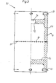
- FIG. 3 shows an electrode 32 cut open in its right half.
- This electrode is an overall cylindrical, self-contained hollow body, the upper end wall 70 of which has a connection opening 74 provided with a thread 72.
- the connection opening 74 serves for screwing in a connection piece, through which the current supply and the electrolyte supply take place, and which is used for fastening the electrode 32 to the hydraulic cylinder 34 (FIG. 2).
- the peripheral wall 76 of the electrode 32 is extended beyond the upper end wall 70 and a lower end wall 78 and carries spacers 80, by means of which the cylindrical outer surface 82 can be adjusted to a defined distance when the electrode is moved into a bore 30 to be machined.
- the spacers 80 are made of insulating material, for example ceramic or plastic.
- the peripheral wall 76 of the electrode 32 is provided in its transverse center plane with electrolyte outlet openings 84.
- the electrolyte outlet openings 84 can be distributed over the lateral surface 82 in accordance with the respective requirements and the desired result.
- the electrolyte outlet openings 84 can be both round and of any other geometry.
- the active surface of the electrode, ie the electrically conductive part of the outer surface 82 can extend over the entire outer surface 82 or can only make up a part of the outer surface 82 due to electrical insulation of part of the surface.
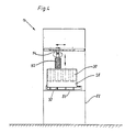
- FIG. 4 shows a mechanical station 14.
- the workpiece 28 rests in a frame 86, which in turn is fastened to a frame 88.
- the frame 86 is provided with adjusting and clamping devices 90 for precisely defined positioning of the workpiece 28.
- a mechanical friction plating tool 92 can be moved on the frame 88 by means of slide guides in all three directions of the space and connected by means of a universal joint 94 to a rotary drive (not shown) which can also be moved up and down.
- the friction plating tool 92 is inserted into one of the bores 30.
- the graphite flakes, exposed mixed crystals or other electrochemical process residues that are exposed during the electrochemical removal are mechanically rubbed and plated, whereby depending on the friction plating tool 92 used, the geometry is also improved and the desired surface roughness and shape can be produced.
- friction p latt istiansstechnikmaschinemaschine 92 are different tools used, such as expandable honing tools similar tools that their processing Generate pressure for example by centrifugal force, rotary brushes with grinding wheels or pure steel or non-ferrous metal rotary brushes.
- expandable honing tools similar tools that their processing Generate pressure for example by centrifugal force, rotary brushes with grinding wheels or pure steel or non-ferrous metal rotary brushes.
- a low processing pressure must be used, with no smearing of the graphite lamellae forming oil pockets and no significant strain hardening of the surface.
- the movement of the friction plating tool 92 can only take place in a rotational, as well as in a rotational and translatory manner.
- a friction plating tool 92 in the form of a honing tool with honing stones made of SiC in ceramic bond and a contact pressure between the largely flat honing stones and the workpiece surface in the order of magnitude of only 10 5 N / m 2 is used, the honing stones take the graphite protruding from the graphite flakes and any residues deposited on the electrochemically machined surface and partially flatten them onto the surface to be machined.
- the graphite together with any deposits is sufficient for a targeted plating of the workpiece surface with graphite and / or M23C6 mixed crystals, preferably in a surface density of 0.5 x 10 -4 to 5 x 10 -4 g / cm 2 .
- the cleaning stations 16 can be omitted.
- the entire device can be constructed from a plurality of stations arranged in series. They can also be designed as a double station, the workpiece being machined alternately in one of the existing mechanical statics and one of the existing electrical stations.
- the alacrolytic removal in the electrostation (s) at the beginning of the fine machining of a workpiece can be greater than towards the end of the machining.
- This also applies to the removal in the mechanical station.
- a charge amount of approximately 5 to 15 As per cm 2 of surface to be processed is advantageously used, this charge amount being implemented for example between 3 and 17 seconds.
- the last mechanical removal advantageously works with an overlap between the tool and the workpiece of only about 1 to 5 ⁇ m. It goes without saying that, after a correspondingly fine purely mechanical pre-processing, a single electrolytic removal and subsequent friction cladding can suffice as the final processing.
- an electrical station is explained as it is used for the machining of cylinder liners for large diesel engines. With such large components, it does not make sense to work with the largest possible electrochemical active area.
- a segment electrode is advantageously used.
- a cylinder liner 96 rests on rollers 98, which can be driven by drums.
- a support frame 100 protrudes into the cylinder liner 96 and is supported on the inner peripheral wall of the cylinder liner 96 by means of rollers 102, so that a carrier 104 fastened to the support frame 100 is aligned relative to the center of the cylinder liner 96.
- a segment electrode 106 is fastened to the carrier 4 and the electrolyte is supplied via lines 108.
- both the cylinder liner 96 and the segment electrode 106 can be moved relative to one another by suitable driving of the frame structure 100.
- the cylinder liner 96 can only be rotated and the segment electrode 106 can only be moved in translation.
- rollers 102 like the segment electrode 106, are advantageously attached to hydraulic cylinders, not shown, with which the support frame 100 can be aligned within the cylinder liner 96 and the gap 112 can be adjusted.
- FIG. 6 shows the lower end of an electrode constructed similarly to the electrode according to FIG. 3 with the peripheral wall 76 and the lower end wall 78, which is formed with a central hole 116.
- a sleeve 123 provided with a slot 118 extends through the hole 116 and is screwed to the end wall 78 by means of a plate 122.
- a bolt 126 whose amplitude of movement is limited by the slot 118 and a pin 128, is movable in the sleeve against the force of a spring 124.
- An electrically insulating cone 129 for example made of ceramic material, is glued to the front end of the bolt, which engages in a conical centering hole in the base of a blind hole to be machined in the workpiece (not shown here) and centers the electrode in the material hole.
- additional stops 132 made of electrically insulating material are provided on the end wall 78.
Abstract
Description
Die Erfindung betrifft ein Verfahren zum Bearbeiten von Oberflächen eines Werkstücks aus kohlenstoffhaltigem Gußeisen gemäß dem Oberbegriff des Anspruchs 1. Die Erfindung betrifft weiter eine Vorrichtung zum Durchführen des Verfahrens.The invention relates to a method for machining surfaces of a workpiece made of carbon-containing cast iron according to the preamble of claim 1. The invention further relates to an apparatus for performing the method.
Für die tribologischen Verhältnisse bei Gleitpaarungen ist die Struktur der Oberfläche von besonderer Bedeutung. Insbesondere bei Graugußzylindern von Brennkraftmaschinen kommt der Oberflächenstruktur des Graugusses für geringen Verschleiß, Reibungsminimierung, Einlaufverhalten und Gasdichtigkeit der Kolbenringe entscheidende Bedeutung zu. Aus Gründen der ölhaltung, die für die VerschleiBminimierung der im Mischreibungsgebiet laufenden Gleitpartner wichtig ist, müssen bei Graugußoberflächen sogenannte Öltaschen durch angeschnittene Graphitlamellen und/oder mechanisch eingearbeitete Rillen vorhanden sein. Zur Reibungsminimierung muß neben der Anwesenheit von Öl eine ausreichend feine Oberflächenrauheit (Mikrorauheit) gegeben sein. Die Geometrie der Oberfläche muß nach bisheriger Auffassung zur Optimierung des Einlaufverhaltens eine genügend aggressive Form haben, so daß ein .gegenseitiges Abarbeiten der Gleitpartner während des Einlaufens möglich ist. Bei der Gleitpaarung Zylinderwand/Kolbenring ergibt sich hieraus in Verbindung mit guter Rundheit eine gute Gasdichtig-Weiter sind übermäßige oberflächliche Kaltverfestigungen zu vermeiden, damit insbesondere die Kolbenringe vor unzulässigem adhäsivem und/ oder abrasivem Verschleiß bewahrt bleiben.The structure of the surface is of particular importance for the tribological conditions in sliding pairings. In the case of gray cast iron cylinders of internal combustion engines in particular, the surface structure of the gray cast iron is of crucial importance for low wear, minimizing friction, running-in behavior and gas tightness of the piston rings. For reasons of oil management, which is important for minimizing wear of the sliding partners running in the mixed friction area, so-called oil pockets with cut graphite lamellae and / or mechanically machined grooves must be available on gray cast iron surfaces. In addition to the presence of oil, a sufficiently fine surface roughness (micro-roughness) must be provided to minimize friction. The geometry of the surface must have a sufficiently aggressive shape in order to optimize the running-in behavior, so that a mutual processing of the sliding partners is possible during running-in. In the case of the sliding pairing cylinder wall / piston ring, this results in good gas tightness in connection with good roundness. In addition, excessive surface hardening should be avoided so that the piston rings in particular are protected from inadmissible adhesive and / or abrasive wear.
Bei sämtlichen bekannten Fertigbearbeitungsverfahren (Drehen, Schleifen, Reiben), ja selbst beim häufig angewandten mechanischen Honen und auch beim elektrochemischen Honen werden die genannten Forderungen in folgenden Punkten nicht zufriedenstellend erfüllt:
- - Bedingt durch die Zerspanungskräfte bei der mechanischen Bearbeitung werden die Graphitlamellen zugeschmiert und wird unter Umständen Graphit bis in die Tiefe aus den Lamellen ausgequetscht.
- - Es erfolgt eine zum Teil beträchtliche Kaltverfestigung der Oberfläche.
- - Aufgrund der zugeschmierten Graphitlamellen ist man gezwungen, eine beträchtliche Oberflächenrauheit zu erzeugen, um einigermaßen befriedigende tribologische Verhältnisse zu erreichen.
- - Due to the cutting forces during mechanical processing, the graphite lamellae are lubricated and, under certain circumstances, graphite is squeezed out of the lamellae deep down.
- - There is in some cases considerable strain hardening of the surface.
- - Due to the smeared graphite lamellae, one is forced to produce a considerable surface roughness in order to achieve reasonably satisfactory tribological conditions.
Diese gewollte Oberflächenrauheit kann nicht als vollwertiger Ersatz für die offenen Graphitlamellen angesehen werden, da sie beim Einlauf der Gleitpartner einen beträchtlichen Verschleiß hervorruft bei dessen Eintritt die ölhaltende Wirkung nachläßt.This deliberate surface roughness cannot be regarded as a full substitute for the open graphite lamellae, since it causes considerable wear when the sliding partners run in, and the oil-holding effect diminishes when this occurs.
Selbst beim Einsatz des elektrochemischen Honens, bei dem das Honwerkzeug sowohl als Elektrode und damit zum elektrochemischen Abtragen, als auch zum mechanischen Abtragen dient, entstehen durch die Wir- kung der mechanisch arbeitenden Honsteine Verquetschungen der Graugußoberfläche. Die Honsteine müssen zur Aufrechterhaltung eines definierten Abstandes zwischen der Elektrode und der Werkstückoberflache relativ stark an die Werkstückoberfläche angepreßt werden. Infolge dieser Anspressung erfolgt eine entsprechend heftige mechanische Bearbeitung der Werkstückoberfläche, die zum Zuschmieren der Graphitlamellen und der oberflächlichen Kaltverfestigung führt. Einzelheiten des elektrochemischen Honens und des dafür verwendeten Werkzeugs sind beispielsweise der Dissertation "Untersuchung des elektrochemischen Honens" von Egbert Scholz an der Technischen Hoch- .schule Aachen vom 22. Juni 1968 entnehmbar.Even when using electrochemical honing, where the honing tool is used both as an electrode and thus for electrochemical removal, as well as serves for mechanical abrasion, caused by the effect of the W IR mechanically operating honing stones Verquetschungen the Graugußoberfläche. To maintain a defined distance between the electrode and the workpiece surface, the honing stones have to be pressed relatively strongly onto the workpiece surface. As a result of this pressure, the workpiece surface is subjected to a correspondingly violent mechanical processing, which leads to the graphite lamellae being smeared and the superficial work hardening. Details of electrochemical honing and the tools used for it can be found, for example, in Egbert Scholz's dissertation "Investigation of electrochemical honing" at the Technical University of Aachen on June 22, 1968.
Das elektrochemische Honen hat nicht nur die geschilderten Unzulänglichkeiten, sondern weist zusätzlich folgende Nachteile auf:
- - Das Werkzeug ist in seinem Aufbau kompliziert und damit teuer, da die mechanischen und elektrischen Werkzeugkomponenten auf engsten Raum untergebracht werden müssen.
- - Eine relativ kleine Elektrodenoberfläche engt die Verfahrensparameter ein. Es ist das Arbeiten mit hohen Stromdichten und verhältnismäßig hohen Elektrolytkonzentrationen erforderlich.
- - Bezüglich der Wahl der Honleisten bestehen starke Beschränkungen. Metallische Bindung, wie bei Diamanthonleisten, kann nicht eingesetzt werden, da hier ein anodischer Abtrag ariolqen würde.
- - Der bei gleichzeitig erfolgender elektrochemischer und mechanischer Abtragung verwendete Elektrolyt ist hinsichtlich Korrosion, Verschleiß, Beeinflussung der mechanischen Abtragung, Neigung des Zusetzens der Honleisten und Beeinflussung der elektrochemischen Abtragung nicht gleichzeitig optimierbar.
- - Schließlich stören die sich in der Elektrolytströmung befindenden Honsteine die Strömungsverhaltnisse des Elektrolyten, was zu ungleichmäßigem abtragen führen kann.
- - The construction of the tool is complicated and therefore expensive, since the mechanical and electrical tool components have to be accommodated in a very small space.
- - A relatively small electrode surface narrows the process parameters. Working with high current densities and relatively high electrolyte concentrations is required.
- - There are severe restrictions on the choice of honing stones. Metallic bonding, as with diamond honing stones, cannot be used, since anodic removal would ariolqen here.
- - The electrolyte used with simultaneous electrochemical and mechanical ablation cannot be optimized at the same time with regard to corrosion, wear, influencing the mechanical ablation, tendency of the honing stones to clog and influencing the electrochemical ablation.
- - Finally, the honing stones in the electrolyte flow disturb the flow conditions of the electrolyte, which can lead to uneven removal.
Der Erfindung liegt die Aufgabe zugrunde, ein Verfahren zum Bearbeiten von Oberflächen eines Werkstücks aus kohlenstoffhaltigem Gußeisen sowie eine Vorrichtung zu dessen Durchführung anzugeben, mit 'dem bzw. der sich eine für die tribologischen Verhältnisse bei Gleitpaarungen besonders geeignete Oberflächenstruktur von kohlenstoffhaltigem Gußeisen auf wirtschaftliche Weise erzielen läßt. Weiter liegt der Erfindung die Aufgabe zugrunde, einen Zylinder für eine Kolbenbrennkraftmaschine mit verbesserten Betriebseigenschaften zu schaffen.The invention has the object of providing a method for processing surfaces of a workpiece of carbon cast iron and an apparatus provide for its implementation, with 'the or to achieve a particularly suitable for the tribological conditions in bearings surface structure of carbon cast iron in an economical manner leaves. Another object of the invention is to create a cylinder for a piston internal combustion engine with improved operating properties.
Der das Verfahren betreffende Teil der Erfindungsaufgabe wird mit den Mermalen des Anspruchs 1 gelöst.The part of the object of the invention relating to the method is solved with the features of claim 1.
Überraschenderweise hat sich herausgestellt, daß durch Trennung des elektrochemischen Abtragens von der rein mechanischen Oberflächenbe- arbeitung tribologisch voll befriedigende Oberflächen auf wirtschaftliche Weise herstellbar sind. Beim elektrochemischen Abtragen bestehen nicht die oben aufgeführten 3eschränkungen von Kombinationswerkzeugen, so daß ein wirtschaftlicher und bezüglich der Maßhaltigkeit befriedigender elektrochemischer Oberflächenabtrag möglich ist. Dieser elektrochemische Oberflächenabtrag ist im allgemeinen nicht in einem Arbeitsgang bis auf die erwünschte Endabmessung möglich, da er durch Freisetzen der Graphitlamellen und Ablagerung der Abbauprodukte auf der Werkstückoberfläche zunehmend zum Stillstand kommt. Beim anschließenden rein mechanischen Reibplattieren der elektrolytisch behandelten Oberfläche wird das vorstehende Graphit abgetragen, ohne daß dabei die Taschen durch benachbartes metallisches Material zugeschmiert werden. Zusätzlich werden beim Reibplattieren meist Oberflächenbestandteile des Grundmaterials, vorallem Mischkristalle, abgerieben und anschließend aufplattiert. Bei dem Reibplattieren handelt es sich also nicht im eigentlichen Sinne um eine das Material abtragende Bearbeitung, sondern um ein Reiben mit gleichzeitigem Plattieren, wobei ein wesentliches Teil des abgeriebenen Materials aufplattiert wird und dadurch eine Oberfläche erhalten wird, bei welcher tragende, ebene Plateaus, die zum Teil mit Graphit, Mischkristallen und/oder etwaigen Elektrolyserückständen plattiert sind, mit offenen Graphitlamellen abwechseln. Eine solche, erfindungsgemäß hergestellte Oberfläche hat im Gegensatz zu bisherigen hellen Oberflächen ein dunkel glänzendes Aussehen.Surprisingly, it has been found that by separating the electrochemical removal from the purely mechanical surface treatment, tribologically fully satisfactory surfaces can be produced economically. In the case of electrochemical removal, there are no 3 restrictions on combination tools, so that they are economical and true to size peaceful electrochemical surface removal is possible. This electrochemical surface removal is generally not possible in one operation up to the final desired gauge, as it increasingly comes the dismantling roducts p by releasing the graphite flakes and deposit on the workpiece surface to a halt. In the subsequent purely mechanical friction plating of the electrolytically treated surface, the above graphite is removed without the pockets being smeared by adjacent metallic material. In addition, surface components of the base material, especially mixed crystals, are usually rubbed off during friction plating and then plated on. Friction plating is therefore not in the actual sense a machining that removes the material, but rather a rubbing with simultaneous plating, whereby a substantial part of the abraded material is plated and thereby a surface is obtained in which load-bearing, flat plateaus that partly plated with graphite, mixed crystals and / or any electrolysis residues, alternate with open graphite fins. In contrast to previous light surfaces, such a surface produced according to the invention has a dark, shiny appearance.
Das aus den Graphitlamellen vorstehende Graphit wird zusammen mit den auf der elektrolytisch bearbeiteten Oberfläche abgesetzten Produkten von dem Reibplattierungswerkzeug, bevorzugt flächigen Reibplattierleisten mit in Keramikbindung,befindlichem SiC und in wässrigem Milieu arbeitend, mitgenommen und auf die Werkstückoberfläche aufplattiertThe p hitlamellen from the foregoing Gra graphite is used together with the stepped surface on the electrolytically processed products from the Reibplattierungswerkzeug, preferably flat Reibplattierleisten with ceramic bond in box situated SiC and working in an aqueous medium, carried along and plated onto the workpiece surface
Die Anzahl der alternierenden Arbeitsschritte elektrochemisches Abtragen und Reibplattieren richtet sich in zweckentsprechender Weise nach den jeweiligen Erfordernissen. Ein aufwendiges Kombinationswerkzeug ist zur Durchführung des erfindungsgemäßen Verfahrens nicht erforderlich. Vielmehr können in ihrem Aufbau an sich bekannte Werkzeuge zum elektrochemischen Abtragen und mechanischen Bearbeiten verwendet werden.The number of alternating electrochemical removal and friction plating steps is appropriately based on the respective requirements. It is a complex combination tool not necessary to carry out the method according to the invention. Rather, tools known per se for electrochemical removal and mechanical processing can be used in their construction.
Die Merkmale der Ansprüche 2 bis 4 ergeben eine für eine Gleitpaarung besonders gut geeignete Oberflächenstruktur.The features of claims 2 to 4 result in a surface structure that is particularly suitable for a sliding pairing.
Gemäß Anspruch 5 werden bei der Durchführung des erfindungsgemäßen Verfahrens beim elektrochemischen Abtragen und mechanischen Bearbeiten zweckmäßigerweise verschiedene Flüssigkeiten eingesetzt, die die jeweiligen Erfordernisse am besten erfüllen. Beim mechanischen Bearbeiten kann beispielsweise mit an sich bekannten Flüssigkeiten gearbeitet werden, die für eine möglichst geringe Oberflächenverfestigung sorgen. Es kann jedoch auch mit einer einzigen-Flüssigkeit, z.B. NaNO3, gearbeitet werden, was die Durchführung des Verfahrens vereinfacht.According to claim 5, when carrying out the method according to the invention, electrochemical removal and mechanical processing expediently use different liquids which best meet the respective requirements. In mechanical processing, for example, liquids known per se can be used, which ensure the least possible surface hardening. However, a single liquid, for example NaNO 3 , can also be used, which simplifies the implementation of the method.
Gemäß dem Anspruch 6 kann die Verschleißfestigkeit der Oberfläche des Werkstücks vergrößert werden. Das Härten kann durch vielerlei an' sich bekannte Verfahren durchgeführt werden, z.B. Umschmelzhärten, induktives Härten, elektroerosives Härten usw.According to claim 6, the wear resistance of the surface of the workpiece can be increased. The hardening can be carried out by a variety of methods known per se, e.g. Remelt hardening, inductive hardening, electroerosive hardening etc.
Der Anspruch 7 kennzeichnet den grundstäzlichen Aufbau der zum Durchführen des erfindungsgemäßen Verfahrens geeigneten Vorrichtung.Claim 7 characterizes the basic structure of the device suitable for carrying out the method according to the invention.
Wenn beim elektrochemischen Abtragen und mechanischen Bearbeiten mit unterschiedlichen Flüssigkeiten gearbeitet wird, ist die Vorrichtung zweckmäßigerweise mit den Mermalen des Anspruchs 8 ausgebildet. Die erfindungsgemäße Vorrichtung kann mit je einer Elektrostation und Mechanikstation ausgerüstet sein, zwischen denen das Werkstück hin und her transportiert wird. Die Vorrichtung kann aber auch mit den Merkmalen des Anspruchs 9 ausgebildet sein, wobei die einzelnen Stationen jeweils auf die darin erfolgenden Arbeitsgänge abgestimmt sindIf different liquids are used for electrochemical removal and mechanical processing, the device is expediently designed with the features of claim 8. The device according to the invention can be equipped with an electrical station and a mechanical station, between which the workpiece is transported back and forth. However, the device can also be designed with the features of claim 9, the individual stations being matched to the work processes taking place therein
Mit den Mermalen des Anspruchs 10 wird eine für die Bearbeitung von Sacklöchern besonders gut geeignete Vorrichtung geschaffen.With the features of
Der Anspruch 11, für den selbständiger Schutz beansprucht wird, kennzeichnet eine zum Bearbeiten von Großbohrungen, z.B. Zylinderbuchsen für Großdieselmotoren, besonders vorteilhafte Ausführungsform der erfindungsgemäßen Vorrichtung.Claim 11, for which independent protection is claimed, characterizes one for machining large bores, e.g. Cylinder liners for large diesel engines, particularly advantageous embodiment of the device according to the invention.
Der Anspruch .12 kennzeichnet einen Zylinder mit einer Lauffläche, welche vorteilhafterweise nach dem erfindungsgemäßen Verfahren hergestellt wird. Diese Lauffläche weist überraschenderweise ausgezeichnete Einlaufeigenschaften und eine hohe Lebensdauer auf, obwohl die Geometrie ihrer Oberfläche in keiner Weise aggressiv ist. Die guten Eigenschaften der Lauffläche, die auch durch rollende Bearbeitung ausgebildet werden könnte, ist vermutlich auf das plättchenartig aufgebrachte Graphit und/oder die M23C6 Mischkristalle sowie etwaige weitere aufplattierte Rückstände zurückzuführen, die beim Einlaufen für den Reibpartner, im vorliegenden Beispiel den oder die Kolbenringe, als Läppmittel wirken. Im eingelaufenen Zustand ergeben sich auf diese Weise ausgezeichnet aufeinander abgestimmte Reibpartner, die aus den fein verteilten offenen Graphitlamellen und ebenfalls fein verteilten, zwischen den Plateaus vorhandenen Grübchen, die Öl halten, mit Schmiermittel versorgt werden. Bei herkömmlichen, mechanisch abtragend bearbeiteten bzw. gehonten Oberflächen ist anfänglich nur ein geringer Oberflächenanteil tragend, der durch Reibverschleiß während des Einlaufens in undefinierter Weise vergrößert wird. Im eingelaufenen Zues stand sind zahlreiche Graphitlamellen zugeschmiert und es stehen zur Ölhaltung nur sowohl hinsichtlich ihrer Verteilung als auch Größe undefinierte Grübchen zur Verfügung.The claim .12 identifies a cylinder with a tread, which is advantageously produced by the method according to the invention. This tread surprisingly has excellent running-in properties and a long service life, although the geometry of its surface is in no way aggressive. The good properties of the tread, which could also be formed by rolling machining, are probably due to the flake-like graphite and / or the M23C6 mixed crystals as well as any other clad residues that the friction partner, in the present example the piston ring or rings, act as a lapping agent. In a g elaufenen state resulting in this way excellent coordinated friction partner, the open of the finely distributed graphite flakes and also finely divided, between the plateaus existing dimples keep oil, with lubrication be supplied with funds. In the case of conventional, mechanically abraded or honed surfaces, only a small proportion of the surface is initially load-bearing, which is increased in an undefined manner by rubbing in during running-in. Numerous graphite lamellae are smeared in the run-in Zues booth and undefined dimples are only available for oil management both in terms of their distribution and size.
Die Erfindung läßt sich für die Bearbeitung fast aller einen Gleitpartner bildenden Oberflächen von Werkstücken aus kohlenstoffhaltigem Gußeisen einsetzen. Besonders vorteilhaft eignet sich die Erfindung für die Bearbeitung von Zylinderlaufbahnen aus Grauguß in Brennkraftmaschinen. Hier werden folgende wesentlichen Vorteile erzielt:
- - längere Lebensdauer der Brennkraftmaschine,
- - bessere Gasdichtigkeit zwischen Kolbenring und Zylinder,
- - verminderter Ölverbrauch,
- - verminderte Kolbenringzahl und damit verminderte Reibung und geringerer Kraftstoffverbrauch.
- - longer service life of the internal combustion engine,
- - better gas tightness between piston ring and cylinder,
- - reduced oil consumption,
- - Reduced number of piston rings and thus reduced friction and lower fuel consumption.
Im Gegensatz zur bisherigen Meinung werden diese Vorteile erzielt ohne daß zum Einlaufen eine in ihrer geometrischen Form besonders "aggressive" Oberfläche zur Verfügung steht.Contrary to the previous opinion, these advantages are achieved without a particularly "aggressive" surface being available for running in.
Die Erfindung wird im folgenden anhand schematischer Zeichnungen beispielsweise und mit weiteren Einzelheiten erläutert:The invention is explained below with reference to schematic drawings, for example and with further details:
Es zeigen:
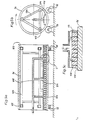
- Fig. 1 eine Seitenansicht einer Vorrichtung zum Bearbeiten einer Bohrung in einem Werkstück aus Gußeisen,
- Fig. 2 eine Elektrostation der Vorrichtung gemäß Fig. 1,
- Fig. 3 eine Elektrode, wie sie in der Elektrostation gemäß Fig. 2 verwendet wird,
- Fig. 4 eine Mechanikstation der Vorrichtung gemäß Fig. 1,
- Fig. 5a einen Längsschnitt durch eine innerhalb einer Zylinderbüchse angeordnete Segmentelektrode,
- Fig. 5b einen Querschnitt durch die Anordnung gemäß Fig. 5a,
- Fig. 5c eine vergrößerte Einzelheit der Anordnung gemäß Fig. 5a und
- Fig. 6 einen Schnitt durch eine besonders für Sacklöcher geeignete Elektrode.
- 1 is a side view of a device for machining a hole in a workpiece made of cast iron,
- 2 shows an electrical station of the device according to FIG. 1,
- 3 shows an electrode as used in the electrical station according to FIG. 2,
- 4 shows a mechanical station of the device according to FIG. 1,
- 5a shows a longitudinal section through a segment electrode arranged within a cylinder liner,
- 5b shows a cross section through the arrangement according to FIG. 5a,
- 5c shows an enlarged detail of the arrangement according to FIGS. 5a and
- Fig. 6 shows a section through an electrode particularly suitable for blind holes.
Gemäß Fig. 1 weist eine Vorrichtung zum Bearbeiten eines Werkstücks aus kohlenstoffhaltigem Gußeisen, beispielsweise von in bekannter Weise mechanisch auf eine Rauhigkeit von etwa 20 um vorbearbeiteten Zylinderlaufflächen eines mit dem Zylinderkopf zusammengegossenen Motorblocks, eine durch hintereinander angeordnete Rollen 6 gebilde-. te Transporteinrichtung 8 auf. Der Antrieb der Rollen 6 ist nicht im einzelnen dargestellt, da die Transporteinrichtung 8 in ihrem Aufbau an sich bekannter Bauart sein kann.1, a device for machining a workpiece made of carbon-containing cast iron, for example mechanically in a known manner to a roughness of about 20 μm pre-machined cylinder running surfaces of an engine block cast together with the cylinder head, is formed by rollers 6 arranged one behind the other. te transport device 8 on. The drive of the rollers 6 is not shown in detail, since the structure of the transport device 8 can be of a type known per se.
Längs der Transporteinrichtung 8, deren Forderrichtung aurcn einen Pfeil 10 angegeben ist, sind abwechselnd Flektrostationen 12 und Mechanikstationen 14 angeordnet, von denen eine dargestellt ist. Zwischen jeder Elektrostation 12 und Mechanikstation 14 befindet sich jeweils eine Reinigungsstation 16.Along the transport device 8, the direction of which is also indicated by an
Der Durchlauf des nicht im einzelnen gezeigten Werkstücks durch den dargestellten Ausschnitt der Vorrichtung ist so, daß das gemäß Fig. ![]()
![]()
In Fig. 1 zusätzlich eingetragen ist ein zur Mechanikstation 14 gehörendes Steuergerät 18, in dem in an sich bekannter Weise, beispielsweise nach dem Staudruckverfahren, der Durchmesser eines im Werkstück ausgebildeten Loches ermittelt wird. Der Meßwert wird dem Steuergerät 18 über eine Meßleitung 20 zugeführt. Anhand des ermittelten Durchmessers wird im Steuergerät 18 die Stromstärke und die Bearbeitungsdauer des Werkstücks beim nachfolgenden elektrochemischen Abtragen in der Elektrostation 12 bestimmt, wobei die Elektrostation 12 über eine Steuerleitung 22 gesteuert wird.1 also shows a
Fic. 2 zeigt Einzelheiten einer Elektrostation 12:
- In
einem Bearbeitungsbehälter 24 befindet sich mittels Justier- und Spannvorrichtung 26 in definierter Lagegehalten ein Werkstück 28, im dargestellten Beispiel ein Metallblockmit vier Sackbohrungen 30. In eine der Bohrungen 30 fährt eine in Fig. 3 näher dargestellte Elektrode 32 ein, welchemit einem Hydraulikzylinder 34 bewegt wird, der aneinem Maschinenständer 36 befestigt ist.Die Elektrode 32 istüber den Hydraulikzylinder 34 in jedwelche Position innerhalb der zu bearbeitenden Bohrung bewegbar.
- A
workpiece 28 is held in a defined position in aprocessing container 24 by means of the adjusting and clampingdevice 26, in the example shown a metal block with fourblind bores 30. Anelectrode 32, shown in more detail in FIGHydraulic cylinder 34 is moved, which is attached to amachine stand 36. Theelectrode 32 can be moved in any position within the bore to be machined via thehydraulic cylinder 34.
Zur Beschickung der Elektrode mit Elektrolyt ist ein Elektrolytvorratsbehälter 40 vorgesehen, welcher über eine Leitung 42 mit einer Pumpe 44 verbunden ist, die Elektrolyt in eine Leitung 46 fördert. Die Leitung 46 setzt sich innerhalb des Bearbeitungsbehälters 24 in einem Schlauch 48 fort, welcher an der hohlen Elektrodenhalterung 50 angeschlossen ist.To supply the electrode with electrolyte, an
Der aus der Elektrode 32 austretende, aus der jeweils bearbeiteten Bohrung 30 herausströmende Elektrolyt gelangt in eine Rücklaufleitung 52, die in einen Zwischenbehälter 54 mündet. Vom Zwischenbehälter 54 wird der Elektrolyt mittels einer Tauchpumpe 56 in eine Zentrifuge 60 gefördert, die zur Reinigung des Elektrolyts dient. Von der Zentrifuge 60 aus gelangt der Elektrolyt durch eine Leitung 62 hindurch zurück.in den Elektrolytvorratsbehälter 40.The electrolyte emerging from the
Zur Stiombeschickung dient ein Stromversorgungsgerät 64, dessen positiver Pol über ein Kabel 66 mit dem Werkstück 28 und dessen negativer Pol über ein Kabel 68 mit der Elektrode 32 verbunden sind.A styrene supply is provided by a
Die elektrochemische Bearbeitung des Werkstücks 28 in der Elektrostation 12 ist an sich bekannt. Die gegenüber dem Hydraulikzylinder 34 elektrisch isolierte Elektrode 32 wird in die jeweils zu bearbeitende Bohrung 30 eingefahren. Der Elektrolytkreislauf wird in Tätigkeit gesetzt und die Stromzufuhr eingeschaltet. Beim elektrochemischen Bearbeitungsvorgang kann die Elektrode 32 stillstehen oder auch entsprechend den Erfordernissen rotieren bzw. rotierend und gleichzeitig translatorisch bewegt werden.The electrochemical processing of the
Fig. 3 zeigt eine in ihrer rechten Hälfte aufgeschnittene Elektrode 32. Diese Elektrode ist ein insgesamt zylindrischer, in sich geschlossener Hohlkörper, dessen obere Stirnwand 70 eine mit einem Gewinde 72 versehene Anschlußöffnung 74 aufweist. Die Anschlußöffnung 74 dient zum Einschrauben eines Anschlußstutzens, durch den hindurch die Stromzufuhr und die Elektrolytzufuhr erfolgt.und der zur Befestigung der Elektrode 32 an dem Hydraulikzylinder 34 (Fig. 2) dient. Die Umfangswand 76 der Elektrode 32 ist über die obere Stirnwand 70 und eine untere Stirnwand 78 hinaus verlängert und trägt Abstandshalter 80, mittels derer die zylindrische Mantelfläche 82 auf einen definierten Abstand beim Einfahren der Elektrode in eine zu bearbeitende Bohrung 30 einjustierbar ist. Es versteht sich, daß die Abstandshal- .ter 80 aus isolierendem Material, beispielsweise Keramik oder Kunststoff, bestehen.3 shows an
Die Umfangswand 76 der Elektrode 32 ist in deren Quermittelebene mit Elektrolytaustrittsöffnungen 84 versehen.The
Es versteht sich, daß die Elektrolytaustrittsöffnungen 84 entsprechend den jeweiligen Erfordernissen und dem erwünschten Ergebnis über die Mantelfläche 82 verteilt sein können. Die Elektrolytaustrittsöffnungen 84 können sowohl rund als auch von beliebiger anderer Geometrie sein. Die Wirkfläche der Elektrode, d.h. der elektrisch leitende Teil der Mantelfläche 82 kann sich über die gesamte Mantelfläche 82 erstrecken oder auch durch elektrische Isolation eines Teils der Oberfläche nur einen Teil der Mantelfläche 82 ausmachen.It goes without saying that the
Fig. 4 zeigt eine Mechanikstation 14. Das Werkstück 28 ruht in einem Gestell 86, welches wiederum an einem Rahmen 88 befestigt ist. Zum genau definierten Positionieren des Werkstücks 28 ist das Gestell 86 mit Justier- und Spanneinrichtungen 90 versehen. Oberhalb des Werkstücks 28 ist am Rahmen 88 ein mechanisches Reibplattierungswerkzeug 92 mittels Schlittenführungen in alle drei Richtungen des Raumes be- wegbar und mittels eines über ein Kardangelenk 94 an einen nicht dargestellten Drehantrieb angeschlossen, welcher zusätzlich auf- und ab- wärts bewegbar ist.4 shows a
Nach Einfahren des Werkstücks 28 in das Gestell 86 und nach genauem Positionieren des Werkstücks 28 mittels der Justier- und Spanneinrichtungen 90 wird das Reibplattierwerkzeug 92 in eine der Bohrungen 30 eingefahren. Dabei werden die bei dem elektrochemischen Abtrag freigelegte Graphitlamellen, freiliegende Mischkristalle oder sonstige elektrochemische Prozessrückstände mechanisch gerieben und aufplattiert, wobei je nach verwendetem Reibplattierungswerkzeug 92 auch eine Verbesserung der Geometrie erfolgt und die gewünschte Oberflächenrauhigkeit und -form erzeugt werden kann.After the
Als Reibplattierungswerkzeug 92 sind verschiedene Werkzeuge verwendbar, beispielsweise Honahlen ähnliche Werkzeuge, die ihren Bearbeitungs druck beispielsweise durch Fliehkraft erzeugen, Rotationsbürsten mit Schleifkörpern oder auch reine Stahl- bzw. NE-Metall-Rotationsbürsten. Damit eine im wesentlichen nur reibplattierende Bearbeitung erfolgt, muß mit niedrigem Bearbeitungsdruck gearbeitet werden, wobei kein Zuschmieren der öltaschen bildenden Graphitlamellen und keine wesentliche Kaltverfestigung der Oberfläche erfolgt. Die Bewegung des Reibplattierungswerkzeugs 92 kann nur rotatorisch als auch rotatorisch und translatorisch erfolgen.As friction p lattierungswerkzeug 92 are different tools used, such as expandable honing tools similar tools that their processing Generate pressure for example by centrifugal force, rotary brushes with grinding wheels or pure steel or non-ferrous metal rotary brushes. In order that essentially only friction-plating processing takes place, a low processing pressure must be used, with no smearing of the graphite lamellae forming oil pockets and no significant strain hardening of the surface. The movement of the
Wenn beispielsweise mit einem Reibplattierungswerkzeug 92 in Art einer Honahle mit Honleisten aus SiC in Keramikbindung und einem Anpressdruck zwischen den weitgehend ebenen Honleisten und der Werkstückoberfläche in der Größenordnung von lediglich 105 N/m2 gearbeitet wird, nehmen die Honleisten das aus den Graphitlamellen vorstehende Graphit und etwaige auf der elektrochemisch bearbeiteten Oberfläche abgeschiedene Rückstände mit und plätten diese teilweise auf die zu bearbeitende Oberfläche auf. Durch die erst nach einem elektrochemischen Abtragungsschritt erfolgende Reibplattierung reicht das Graphit zusammen mit etwaigen Ablagerungen aus, um eine gezielte Aufplattie- rung der Werkstückoberfläche mit Graphit und/oder M23C6 Mischkristallen, bevorzugt in einer Flächendichte von 0,5 x 10⁻⁴ bis 5 x 10⁻⁴ g/cm2, zu erzeugen.If, for example, a
Wenn bei der mechanisch reibplattierenden Bearbeitung anstatt mit Schneidöl oder Emulsion mit Elektrolyt gearbeitet wird, können die Reinigungsstationen 16 (Fig. 1) entfallen.If the mechanically friction-plating machining is carried out using electrolyte instead of cutting oil or emulsion, the cleaning stations 16 (FIG. 1) can be omitted.
Die gesamte Vorrichtung kann, wie in Fig. 1 dargestellt, aus mehreren in Reihe hintereinander angeordneten Stationen aufgebaut sein. Sie kann auch als Doppelstation ausgeführt sein, wobei das Werkstück abwechselnd in der einen vorhandenen Mechanikstaticn und der einen vorhandenen Elektrostation bearbeitet wird.As shown in FIG. 1, the entire device can be constructed from a plurality of stations arranged in series. they can also be designed as a double station, the workpiece being machined alternately in one of the existing mechanical statics and one of the existing electrical stations.
Desweiteren versteht sich, daß die in der oder den Elektrostationen erfolgende alaktrolytische Abtragung zu Beginn der Feinbearbeitung eines Werkstücks größer sein kann als gegen Schluß der Bearbeitung. Dies gilt ebenso für den Abtrag in der Mechanikstation. Vorteilhafterweise wird im letzten Arbeitsschritt des elektrolytischen Abtrags mit einer Ladungsmenge von etwa 5 bis 15 As je cm2 zu bearbeitender Oberfläche gearbeitet, wobei diese Ladungsmenge beispielsweise zwischen 3 und 17s umgesetzt wird. Beim letzten mechanischen Abtragen wird vorteilhafterweise mit einer Überlappung zwischen Werkzeug und Werkstück von lediglich etwa 1 bis 5 µm gearbeitet. Es versteht sich, daß nach entsprechend feiner rein mechanischen Vorbearbeitung eine einzige elektrolytische Abtragung und anschließende Reibplattierung als Endbearbeitung ausreichen können.Furthermore, it goes without saying that the alacrolytic removal in the electrostation (s) at the beginning of the fine machining of a workpiece can be greater than towards the end of the machining. This also applies to the removal in the mechanical station. In the last working step of the electrolytic removal, a charge amount of approximately 5 to 15 As per cm 2 of surface to be processed is advantageously used, this charge amount being implemented for example between 3 and 17 seconds. The last mechanical removal advantageously works with an overlap between the tool and the workpiece of only about 1 to 5 μm. It goes without saying that, after a correspondingly fine purely mechanical pre-processing, a single electrolytic removal and subsequent friction cladding can suffice as the final processing.
Für höchst beanspruchte Werkstückoberflächen empfiehlt sich zwischen wenigstens einem der mechanischen Bearbeitungsschritte und der elektrolytischen Bearbeitungsschritte einen Arbeitsschritt einzuschieben, in welchem die Oberfläche gehärtet wird.For highly stressed workpiece surfaces, it is advisable to insert a work step between at least one of the mechanical processing steps and the electrolytic processing steps, in which the surface is hardened.
Anhand Figuren 5a, 5b und 5c ist eine Elektrostation erläutert, wie sie für die Bearbeitung von Zylinderbuchsen für Großdieselmotoren eingesetzt wird. Bei solchen Grcßbauteilen ist es nicht sinnvoll, mit der größtmöglichen elektrochemischen Wirkfläche zu arbeiten. Vorteilhafterweise wird eine Segmentelektrode verwendet.5a, 5b and 5c, an electrical station is explained as it is used for the machining of cylinder liners for large diesel engines. With such large components, it does not make sense to work with the largest possible electrochemical active area. A segment electrode is advantageously used.
Eine Zylinderbüchse 96 ruht auf Rollen 98, weiche drenangetrieben sein können. In die Zylinderbüchse 96 ragt ein Tragrahmen 100 ein, welcher sich mittels Rollen 102 an der inneren Umfangswand der Zylinderbüchse 96 abstützt, so daß ein am Tragrahmen 100 befestigter Träger 104 relativ zur Mitte der Zylinderbüchse 96 ausgerichtet ist. An den Träger 4 ist eine Segmentelektrode 106 befestigt, welcher Elektrolyt über Leitungen 108 zugeführt wird.A
Fig. 5c zeigt die in Fig. 5a mit c bezeichnete Einzelheit in vergrößertem Maßstab:
- Wie ersichtlich ist die
Segmentelektrode 106 derart gehalten, daß zwischen der äußeren Oberfläche ihrer Außenwand 110 und der Zylinderbüchse 96 ein kleinerSpalt 112 verbleibt.Die Außenwand 110ist mit Elektrolytaustrittsöffnungen 114 versehen, durch welche der derSegmentelektrode 106 zugeführte Elektrolyt inden Spalt 112 austritt
- As can be seen, the
segment electrode 106 is held in such a way that asmall gap 112 remains between the outer surface of itsouter wall 110 and thecylinder liner 96. Theouter wall 110 is provided withelectrolyte outlet openings 114, through which the electrolyte supplied to thesegment electrode 106 exits into thegap 112
Beim elektrolytischen Abtragen können sowohl die Zylinderbüchse 96 als auch durch geeigneten Antrieb der Rahmenstruktur 100 die Segmentelektrode 106 relativ zueinander bewegt werden. Dabei kann beispielsweise die Zylinderbüchse 96 nur gedreht und die Segmentelektrode 106 nur translatorisch bewegt werden. Es versteht sich, daß Rollen 102 ebenso wie die Segmentelektrode 106 vorteilhafterweise an nicht dargestellten Hydraulikzylindern angebracht sind, mit welchen der Tragrahmen 100 innerhalb der Zylinderbüchse 96 ausrichtbar und der Spalt 112 einstellbar ist.During electrolytic removal, both the
Fig. 6 zeigt das untere Ende einer ähnlich der Elektrode gemäß Fig. 3 aufgebauten Elektrode mit der Umfangswand 76 und der unteren Stirnwand 78, die mit einem zentralen Loch 116 ausgebildet ist. Durch das Loch 116 erstreckt sich eine mit einem Schlitz 118 versehene Hülse 123, welche mittels einer Platte 122 mit der Stirnwand 78 verschraubt ist. In der Hülse ist gegen die Kraft einer Feder 124 ein Bolzen 126 beweglich, dessen Bewegungsamplitude durch den Schlitz 118 und einen Zapfen 128 begrenzt ist. Auf das vordere Ende des Bolzens ist ein elektrisch isolierender Konus 129, z.B. aus Keramikmaterial, geklebt, welcher in eine konische Zentrierbohrung im Grund einer zu bearbeitenden Sackbohrung des hier nicht gezeigten Werkstücks eingreift und die Elektrode in der Sachbohrung zentriert. Zur Entlastung der beschriebenen zentrierenden Führung sind an der Stirnwand 78 zusätzliche Anschläge 132 aus elektrisch isolierendem Material vorgesehen.FIG. 6 shows the lower end of an electrode constructed similarly to the electrode according to FIG. 3 with the
Claims (12)
Priority Applications (1)
| Application Number | Priority Date | Filing Date | Title |
|---|---|---|---|
| AT82103349T ATE26472T1 (en) | 1981-05-19 | 1982-04-21 | METHOD FOR FINISHING SURFACES OF A CARBON CAST IRON WORKPIECE, AND DEVICE FOR CARRYING OUT THE METHOD AND CYLINDERS MADE OF GRAY IRON. |
Applications Claiming Priority (2)
| Application Number | Priority Date | Filing Date | Title |
|---|---|---|---|
| DE3119847A DE3119847C2 (en) | 1981-05-19 | 1981-05-19 | Cylinders of a reciprocating internal combustion engine made of gray cast iron, method for machining surfaces of a workpiece made of carbon-containing cast iron, in particular cylinders, and device for carrying out the method |
| DE3119847 | 1981-05-19 |
Publications (3)
| Publication Number | Publication Date |
|---|---|
| EP0065645A2 true EP0065645A2 (en) | 1982-12-01 |
| EP0065645A3 EP0065645A3 (en) | 1984-09-05 |
| EP0065645B1 EP0065645B1 (en) | 1987-04-08 |
Family
ID=6132670
Family Applications (1)
| Application Number | Title | Priority Date | Filing Date |
|---|---|---|---|
| EP82103349A Expired EP0065645B1 (en) | 1981-05-19 | 1982-04-21 | Process for treating surfaces of cast iron that contains carbon, as well as apparatus for carrying out the process and cylinder consisting of a grey cast iron casting |
Country Status (8)
| Country | Link |
|---|---|
| US (1) | US4483755A (en) |
| EP (1) | EP0065645B1 (en) |
| JP (1) | JPS581100A (en) |
| AT (1) | ATE26472T1 (en) |
| BR (1) | BR8202873A (en) |
| CA (1) | CA1213244A (en) |
| DE (2) | DE3119847C2 (en) |
| ES (2) | ES8304462A1 (en) |
Cited By (1)
| Publication number | Priority date | Publication date | Assignee | Title |
|---|---|---|---|---|
| EP0169984A2 (en) * | 1984-07-27 | 1986-02-05 | Audi Ag | Method of producing the raceways of cast iron cylinders of a reciprocating engine |
Families Citing this family (17)
| Publication number | Priority date | Publication date | Assignee | Title |
|---|---|---|---|---|
| DE3217818A1 (en) * | 1982-05-12 | 1983-11-17 | Audi Nsu Auto Union Ag, 7107 Neckarsulm | METHOD FOR PRODUCING SIZED, DEFINED TRIBOLOGICAL PROPERTIES WITH SURFACES OF WORKPIECES FROM CARBONED CAST IRON |
| JPS6062419A (en) * | 1983-09-12 | 1985-04-10 | Japax Inc | Fully automatic wire-cut electric spark machine |
| DE3537172A1 (en) * | 1985-10-18 | 1987-04-23 | Audi Ag | Method for working a bore and device for carrying out the method |
| JPS6311676U (en) * | 1986-07-08 | 1988-01-26 | ||
| DE3719796A1 (en) * | 1987-06-13 | 1988-12-22 | Gehring Gmbh Maschf | METHOD AND TOOL FOR MACHINING SURFACES, ESPECIALLY THE RUNNINGS OF COMBUSTION ENGINES |
| DE3817259A1 (en) * | 1988-05-20 | 1989-11-23 | Audi Ag | Method and device for machining bores |
| JPH0431174U (en) * | 1990-07-06 | 1992-03-12 | ||
| US5191864A (en) * | 1992-02-03 | 1993-03-09 | Briggs & Stratton Corporation | Engine cylinder bore |
| DE4440713C2 (en) * | 1993-11-23 | 1998-07-02 | Volkswagen Ag | Process for producing sliding surfaces on cast iron parts, in particular cylinder raceways of internal combustion engines, and honing tool for carrying out the process |
| GB2356870A (en) * | 1999-12-01 | 2001-06-06 | Secr Defence | Dissolution of metal structures |
| US6786807B2 (en) | 2002-09-03 | 2004-09-07 | Micromatic Operations, Inc. | Universal coupling for machine tool |
| US6935003B2 (en) * | 2003-02-28 | 2005-08-30 | National University Of Singapore | Compound fabrication process and apparatus |
| JP5283562B2 (en) * | 2009-05-15 | 2013-09-04 | オリオン機械株式会社 | Cooling system |
| DE102009031337A1 (en) | 2009-07-01 | 2011-01-05 | Daimler Ag | Method for processing surface of component i.e. cylinder barrel of internal combustion engine, involves brushing component surface by brushing process, and processing component surface by machining process i.e. lapping-honing process |
| DE102010020227B4 (en) | 2010-05-11 | 2023-10-26 | Ks Kolbenschmidt Gmbh | Method for generating an arbitrarily designed geometry on pistons of internal combustion engines and a device for carrying out the method |
| CN107345767A (en) * | 2016-05-06 | 2017-11-14 | 沈阳铝镁设计研究院有限公司 | A kind of burnt waste heat recovery of pot type burner high-temperature calcination and cooling device |
| CN115979010B (en) * | 2022-12-31 | 2024-03-19 | 山东金旺装备科技有限公司 | Petroleum coke tank calciner waste heat utilization system |
Citations (2)
| Publication number | Priority date | Publication date | Assignee | Title |
|---|---|---|---|---|
| FR1273987A (en) * | 1960-09-09 | 1961-10-20 | Jacquet Hispano Suiza Soc | Improvements made to processes to improve the friction and rolling conditions of shafts, toothed wheels, etc. |
| DE2531013A1 (en) * | 1975-07-11 | 1977-01-27 | Audi Nsu Auto Union Ag | METHOD FOR PRODUCING SLIDING SURFACES FROM CAST IRON |
Family Cites Families (17)
| Publication number | Priority date | Publication date | Assignee | Title |
|---|---|---|---|---|
| US1844316A (en) * | 1929-05-27 | 1932-02-09 | Simplicity Mfg Company | Boring and grinding machine |
| US1939205A (en) * | 1932-07-15 | 1933-12-12 | Micromatic Hone Corp | Honing tool and fixture |
| DE683262C (en) * | 1935-11-08 | 1939-11-02 | Schmidt Gmbh Karl | Cylinder sleeve for internal combustion engines with reciprocating pistons |
| DE733053C (en) * | 1938-11-11 | 1943-03-18 | Willy Franzenburg | Device for surface pressure for cylinder liners |
| DE907616C (en) * | 1943-11-07 | 1954-03-25 | Hans Burkhardt Dr Ing | Process for processing metal objects to undersize |
| DE816555C (en) * | 1950-05-12 | 1951-10-11 | Walther Groepler | Method for lubricating or smoothing the friction surfaces of the wheel flanges on wheels, in particular on rail vehicles, by coating with a lubricant |
| DE811768C (en) * | 1950-05-31 | 1951-08-23 | Deutsche Edelstahlwerke Ag | Shaft, especially crankshaft |
| US3296747A (en) * | 1964-10-23 | 1967-01-10 | Goetzewerke | Method of and apparatus for honing piston rings |
| US3405049A (en) * | 1964-10-27 | 1968-10-08 | Micromatic Hone Corp | Cylindrical bore sizing and finishing device |
| US3468784A (en) * | 1965-10-13 | 1969-09-23 | Gen Motors Corp | Electrical stock removal apparatus |
| US3499830A (en) * | 1967-11-20 | 1970-03-10 | Cincinnati Milling Machine Co | Apparatus for electrochemically forming and finishing gears |
| US3751346A (en) * | 1971-08-16 | 1973-08-07 | Micromatic Ind Inc | Combined plating and honing method and apparatus |
| DE2229944C3 (en) * | 1972-06-20 | 1975-09-04 | John F. Dipl.-Ing. Elmhurst Ill. Jumer (V.St.A.) | Device for electrolytic polishing of the inner wall of elongated cylindrical containers |
| DE2538585A1 (en) * | 1975-08-29 | 1977-03-03 | John F Jumer | Polishing large cylindrical vessesl with closed ends - tilting vessel to horizontal so that minimum polishing fluid used |
| GB1591804A (en) * | 1977-01-10 | 1981-06-24 | British Petroleum Co | Bearing surface |
| DE2715945C2 (en) * | 1977-04-09 | 1984-04-26 | Henninghaus, Ferdinand, 4000 Düsseldorf | Device for the drawn boring of tubular workpieces |
| US4312900A (en) * | 1980-06-09 | 1982-01-26 | Ford Motor Company | Method of treating sliding metal contact surfaces |
-
1981
- 1981-05-19 DE DE3119847A patent/DE3119847C2/en not_active Expired
-
1982
- 1982-04-21 AT AT82103349T patent/ATE26472T1/en not_active IP Right Cessation
- 1982-04-21 DE DE8282103349T patent/DE3276011D1/en not_active Expired
- 1982-04-21 EP EP82103349A patent/EP0065645B1/en not_active Expired
- 1982-05-17 US US06/379,032 patent/US4483755A/en not_active Expired - Fee Related
- 1982-05-18 BR BR8202873A patent/BR8202873A/en not_active IP Right Cessation
- 1982-05-18 CA CA000403144A patent/CA1213244A/en not_active Expired
- 1982-05-19 JP JP57085648A patent/JPS581100A/en active Granted
- 1982-05-19 ES ES512373A patent/ES8304462A1/en not_active Expired
- 1982-05-19 ES ES512374A patent/ES512374A0/en active Granted
Patent Citations (2)
| Publication number | Priority date | Publication date | Assignee | Title |
|---|---|---|---|---|
| FR1273987A (en) * | 1960-09-09 | 1961-10-20 | Jacquet Hispano Suiza Soc | Improvements made to processes to improve the friction and rolling conditions of shafts, toothed wheels, etc. |
| DE2531013A1 (en) * | 1975-07-11 | 1977-01-27 | Audi Nsu Auto Union Ag | METHOD FOR PRODUCING SLIDING SURFACES FROM CAST IRON |
Cited By (2)
| Publication number | Priority date | Publication date | Assignee | Title |
|---|---|---|---|---|
| EP0169984A2 (en) * | 1984-07-27 | 1986-02-05 | Audi Ag | Method of producing the raceways of cast iron cylinders of a reciprocating engine |
| EP0169984A3 (en) * | 1984-07-27 | 1987-12-02 | Audi Ag | Method of producing the raceways of cast iron cylinders of a reciprocating engine and device for carrying out the method |
Also Published As
| Publication number | Publication date |
|---|---|
| DE3119847C2 (en) | 1983-12-29 |
| ES8304830A1 (en) | 1983-04-01 |
| ES512374A0 (en) | 1983-04-01 |
| EP0065645B1 (en) | 1987-04-08 |
| DE3119847A1 (en) | 1983-02-10 |
| ES512373A0 (en) | 1983-03-01 |
| JPS6230279B2 (en) | 1987-07-01 |
| JPS581100A (en) | 1983-01-06 |
| CA1213244A (en) | 1986-10-28 |
| ES8304462A1 (en) | 1983-03-01 |
| BR8202873A (en) | 1983-04-26 |
| DE3276011D1 (en) | 1987-05-14 |
| US4483755A (en) | 1984-11-20 |
| EP0065645A3 (en) | 1984-09-05 |
| ATE26472T1 (en) | 1987-04-15 |
Similar Documents
| Publication | Publication Date | Title |
|---|---|---|
| EP0065645B1 (en) | Process for treating surfaces of cast iron that contains carbon, as well as apparatus for carrying out the process and cylinder consisting of a grey cast iron casting | |
| DE758779C (en) | Process for protecting metal surfaces subject to friction, in particular cylinder bores | |
| DE112005002175T5 (en) | Electrochemical machining tool and process for machining a product with same | |
| DE102010020227B4 (en) | Method for generating an arbitrarily designed geometry on pistons of internal combustion engines and a device for carrying out the method | |
| EP0335277B1 (en) | Method and apparatus for selective electroplating | |
| DE102016114969A1 (en) | Method and apparatus for electrolytic polishing and method for producing a cathode | |
| DE102013109025A1 (en) | sliding surface | |
| DE4440713C2 (en) | Process for producing sliding surfaces on cast iron parts, in particular cylinder raceways of internal combustion engines, and honing tool for carrying out the process | |
| WO2013182539A2 (en) | Partial structuring of sliding surfaces | |
| DE3210495A1 (en) | Method of producing bearing surfaces | |
| DE3817259A1 (en) | Method and device for machining bores | |
| DE1812312A1 (en) | Methods and tools for external cylindrical machining, especially by electrolytic grinding | |
| DE3715454C2 (en) | ||
| DE3149120C2 (en) | Tool for machining the surfaces of holes in carbonaceous cast iron | |
| DE102012104817B4 (en) | Method and machine for machining rotationally symmetrical sliding bearing points by means of PECM | |
| DE102005023293A1 (en) | Elctrochemical erosion apparatus for forming indentations, especially lubricant pockets, in metallic surfaces comprises individual electrodes with shape and distribution copying the indentations | |
| DE10134573C2 (en) | Method for reducing wear on a tool in metal cutting | |
| DE102011084051B4 (en) | Coated piston ring with radially increasing layer thickness and process for its production | |
| DE4142952C1 (en) | ||
| DE2247956C3 (en) | Workpiece with galvanically applied nickel coating and bath for its deposition | |
| DE2326408C3 (en) | Method for producing bevels on the slot edges of reciprocating piston engine cylinders | |
| DE1914821A1 (en) | Method and device for the electrochemical machining of a workpiece | |
| DE102011084052A1 (en) | Coated piston ring for use in combustion engine such as reciprocating piston engine, has base body whose outer circumferential surface and flank surface form outer edge, which exhibits ridge or ablation having specific range width | |
| DE3716058A1 (en) | Method of reworking rotating components full of wear marks | |
| DE10344722B4 (en) | Method for producing a workpiece having at least one bearing eye |
Legal Events
| Date | Code | Title | Description |
|---|---|---|---|
| PUAI | Public reference made under article 153(3) epc to a published international application that has entered the european phase |
Free format text: ORIGINAL CODE: 0009012 |
|
| AK | Designated contracting states |
Designated state(s): AT CH DE FR GB IT LI SE |
|
| PUAL | Search report despatched |
Free format text: ORIGINAL CODE: 0009013 |
|
| AK | Designated contracting states |
Designated state(s): AT CH DE FR GB IT LI SE |
|
| 17P | Request for examination filed |
Effective date: 19840926 |
|
| RAP1 | Party data changed (applicant data changed or rights of an application transferred) |
Owner name: AUDI AG |
|
| ITF | It: translation for a ep patent filed |
Owner name: DE DOMINICIS & MAYER S.R.L. |
|
| GRAA | (expected) grant |
Free format text: ORIGINAL CODE: 0009210 |
|
| AK | Designated contracting states |
Kind code of ref document: B1 Designated state(s): AT CH DE FR GB IT LI SE |
|
| REF | Corresponds to: |
Ref document number: 26472 Country of ref document: AT Date of ref document: 19870415 Kind code of ref document: T |
|
| REF | Corresponds to: |
Ref document number: 3276011 Country of ref document: DE Date of ref document: 19870514 |
|
| ET | Fr: translation filed | ||
| PLBE | No opposition filed within time limit |
Free format text: ORIGINAL CODE: 0009261 |
|
| STAA | Information on the status of an ep patent application or granted ep patent |
Free format text: STATUS: NO OPPOSITION FILED WITHIN TIME LIMIT |
|
| 26N | No opposition filed | ||
| ITTA | It: last paid annual fee | ||
| PGFP | Annual fee paid to national office [announced via postgrant information from national office to epo] |
Ref country code: GB Payment date: 19930325 Year of fee payment: 12 |
|
| PGFP | Annual fee paid to national office [announced via postgrant information from national office to epo] |
Ref country code: FR Payment date: 19930406 Year of fee payment: 12 |
|
| PGFP | Annual fee paid to national office [announced via postgrant information from national office to epo] |
Ref country code: SE Payment date: 19930415 Year of fee payment: 12 Ref country code: AT Payment date: 19930415 Year of fee payment: 12 |
|
| PGFP | Annual fee paid to national office [announced via postgrant information from national office to epo] |
Ref country code: CH Payment date: 19930625 Year of fee payment: 12 |
|
| PG25 | Lapsed in a contracting state [announced via postgrant information from national office to epo] |
Ref country code: GB Effective date: 19940421 Ref country code: AT Effective date: 19940421 |
|
| PG25 | Lapsed in a contracting state [announced via postgrant information from national office to epo] |
Ref country code: SE Effective date: 19940422 |
|
| PG25 | Lapsed in a contracting state [announced via postgrant information from national office to epo] |
Ref country code: LI Effective date: 19940430 Ref country code: CH Effective date: 19940430 |
|
| GBPC | Gb: european patent ceased through non-payment of renewal fee |
Effective date: 19940421 |
|
| PG25 | Lapsed in a contracting state [announced via postgrant information from national office to epo] |
Ref country code: FR Effective date: 19941229 |
|
| REG | Reference to a national code |
Ref country code: CH Ref legal event code: PL |
|
| EUG | Se: european patent has lapsed |
Ref document number: 82103349.5 Effective date: 19941110 |
|
| REG | Reference to a national code |
Ref country code: FR Ref legal event code: ST |
|
| PGFP | Annual fee paid to national office [announced via postgrant information from national office to epo] |
Ref country code: DE Payment date: 19960426 Year of fee payment: 15 |
|
| PG25 | Lapsed in a contracting state [announced via postgrant information from national office to epo] |
Ref country code: DE Free format text: LAPSE BECAUSE OF NON-PAYMENT OF DUE FEES Effective date: 19980101 |