EP0064391A1 - Verfahren und Gerät zum Steuern eines Schrittmotors - Google Patents
Verfahren und Gerät zum Steuern eines Schrittmotors Download PDFInfo
- Publication number
- EP0064391A1 EP0064391A1 EP82302197A EP82302197A EP0064391A1 EP 0064391 A1 EP0064391 A1 EP 0064391A1 EP 82302197 A EP82302197 A EP 82302197A EP 82302197 A EP82302197 A EP 82302197A EP 0064391 A1 EP0064391 A1 EP 0064391A1
- Authority
- EP
- European Patent Office
- Prior art keywords
- stepper motor
- current
- pulse
- track
- signal processing
- Prior art date
- Legal status (The legal status is an assumption and is not a legal conclusion. Google has not performed a legal analysis and makes no representation as to the accuracy of the status listed.)
- Granted
Links
Images


Classifications
-
- G—PHYSICS
- G05—CONTROLLING; REGULATING
- G05B—CONTROL OR REGULATING SYSTEMS IN GENERAL; FUNCTIONAL ELEMENTS OF SUCH SYSTEMS; MONITORING OR TESTING ARRANGEMENTS FOR SUCH SYSTEMS OR ELEMENTS
- G05B19/00—Programme-control systems
- G05B19/02—Programme-control systems electric
- G05B19/18—Numerical control [NC], i.e. automatically operating machines, in particular machine tools, e.g. in a manufacturing environment, so as to execute positioning, movement or co-ordinated operations by means of programme data in numerical form
- G05B19/19—Numerical control [NC], i.e. automatically operating machines, in particular machine tools, e.g. in a manufacturing environment, so as to execute positioning, movement or co-ordinated operations by means of programme data in numerical form characterised by positioning or contouring control systems, e.g. to control position from one programmed point to another or to control movement along a programmed continuous path
- G05B19/40—Open loop systems, e.g. using stepping motor
-
- H—ELECTRICITY
- H02—GENERATION; CONVERSION OR DISTRIBUTION OF ELECTRIC POWER
- H02P—CONTROL OR REGULATION OF ELECTRIC MOTORS, ELECTRIC GENERATORS OR DYNAMO-ELECTRIC CONVERTERS; CONTROLLING TRANSFORMERS, REACTORS OR CHOKE COILS
- H02P8/00—Arrangements for controlling dynamo-electric motors of the kind having motors rotating step by step
- H02P8/14—Arrangements for controlling speed or speed and torque
- H02P8/20—Arrangements for controlling speed or speed and torque characterised by bidirectional operation
-
- H—ELECTRICITY
- H02—GENERATION; CONVERSION OR DISTRIBUTION OF ELECTRIC POWER
- H02P—CONTROL OR REGULATION OF ELECTRIC MOTORS, ELECTRIC GENERATORS OR DYNAMO-ELECTRIC CONVERTERS; CONTROLLING TRANSFORMERS, REACTORS OR CHOKE COILS
- H02P8/00—Arrangements for controlling dynamo-electric motors of the kind having motors rotating step by step
- H02P8/32—Reducing overshoot or oscillation, e.g. damping
-
- G—PHYSICS
- G05—CONTROLLING; REGULATING
- G05B—CONTROL OR REGULATING SYSTEMS IN GENERAL; FUNCTIONAL ELEMENTS OF SUCH SYSTEMS; MONITORING OR TESTING ARRANGEMENTS FOR SUCH SYSTEMS OR ELEMENTS
- G05B2219/00—Program-control systems
- G05B2219/30—Nc systems
- G05B2219/41—Servomotor, servo controller till figures
- G05B2219/41081—Approach position from same direction
-
- G—PHYSICS
- G05—CONTROLLING; REGULATING
- G05B—CONTROL OR REGULATING SYSTEMS IN GENERAL; FUNCTIONAL ELEMENTS OF SUCH SYSTEMS; MONITORING OR TESTING ARRANGEMENTS FOR SUCH SYSTEMS OR ELEMENTS
- G05B2219/00—Program-control systems
- G05B2219/30—Nc systems
- G05B2219/41—Servomotor, servo controller till figures
- G05B2219/41248—Adapting characteristics of servo
Definitions
- the present invention relates to a method and apparatus for controlling a stepper motor and particularly, but not exclusively, for use with a computer disk drive unit of the kind disclosed in British Patent Application No. 8041323.
- the present invention is realised in a programmable circuit-which is particularly, but not exclusively, suitable for open-loop control of stepper motors.
- the contents of this patent relate to the use of a microprocesser-based system for the control of various stepper motors in a disk file, particularly; minimisation of stepper motor oscillations for a single step, acceleration and deceleration of the stepper motor for multi-track seeks; and reduction of angular hysteresis due to the mechanical/magnetic properties of the stepper motor construction.
- the stepper motor in a computer disk drive unit is used as the actuator for radially positioning the read/write head over the tracks on the disk surface.
- Detente positions of the stepper motor correspond to track positions on the disk.
- the stepper motor rotates by a predetermined amount in response to a winding or windings being energised. When windings are energised in succession this corresponds to the supply of pulses of current to the motor.
- the control of the rate of pulses applied to the stepper motor enables control of the rotational speed of the stepper motor and hence the time taken for the head to move between tracks on the disk.
- the speed of response of the stepper motor and consequently the time taken for the read/write head to move from one track to another is a function of the pulse rate applied to the stepper motor.
- a drive circuit 2 F ig. 1 which produces pulses in response to instructions received from a system drive controller or "host" 3, which may be, for example, a computer, or terminal or the like. Movement of the arm 4 is controlled by the stepper motor 1.
- the drive circuit 2 comprises hard-wired discrete circuit components.
- the speed at which the stepper motor may be driven in response to an applied pulse rate is partly a function of the inertia of the combination of the motor and the load consisting of, for example, the stainless steel belt, thermal compensation mechanism (British Patent Application No. 8041323) spindles, arm and the read/ write head.
- the inertia and torque specification of the motor determine the maximum acceleration and maximum deceleration of the motor.
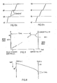
- the motor receives pulses to move the read/write head from one track 5 to another track 6 on the disk as shown in Fig.
- step pulses may be implemented for example either by a discrete electronic circuit or by a microprocessor- based circuit.
- the microprocessor gives certain advantages over discrete components, the 'ringing' or oscillation feature is still present when moving between tracks and is particularly evident and undesirable on reaching the desired track. This is a disadvantage of such proposed stepper motor control systems.
- Fig. 2 The idealised situation depicted in Fig. 2 shows that the stepper motor is exactly at rest at track 6. Of course this does not occur in practice. It is possible to consider modifying the deceleration ramp i.e. the rate of issue of pulses to bring the motor to rest at track 6.'- However, even this does not occur in practice due to.inertia of the drive system and overshooting still occurs. In addition, overshoots across the tracks can be accumulated such that the drive is not synchronised to the operation of the system and the 'headt can lose its intended address.
- BPD back-phase damping
- a pulse of the reverse phase is applied to the stepper motor to act as a braking mechanism and slow the.speed of the motor and hence reduces the overshoot.
- the winding of; the stepper motor corresponding to the last track is then energised to cause the stepper motor to move to the last track.
- This technique can be used with either the. discrete component drive circuit or with the microprocessor controlled drive circuit.
- the time of starting and duration of the Back Phase Damping may vary with each winding of the stepper motor and may also vary between nominally similar stepper motors. Thus many different parameters need to be defined.
- the acceleration and deceleration parts of the speed profile are usually represented by a linear ramp (Fig. 2).
- the inertial characteristics of a particular design of disk drive depend on components such as weight, pre-load friction and machining tolerances as well as the type of stepper motor used and consequently the acceleration'and deceleration parts of the speed profile may be any one of a variety of shapes lOa, lOb such as exponential, sigmoid etc. depending on the inertial characteristics of the particular drive unit design and the specification of the selected stepper motor (Fig. 4).
- the stepper motor drive it is essential to know the torque/speed characteristics of the motor exactly so that the pulse rate applied to the stepper motor is correctly modified to reduce the time taken to move between tracks. That is, the movement of the read/write head is optimised to reach the desired track in the minimum time. If the pulse rate from the control circuit is not matched to the particular torque/speed profile, then the speed of the motor may be too slow and consequently the access time is not minimised or, if the pulse rate is too high the motor may stall with loss of synchronisation. With hard-wired circuits composed of discrete components, it is relatively difficult to match the pulse rate closely to the motor torque/speed characteristic of a particular stepper motor. 'With a previously proposed microprocessor controlled drive circuit, the circuit is not suitable for use with motors having non-linear speed/time characteristics thus its usefullness is limited in practice as many motors have non-linear characteristics.
- a further disadvantage of conventional stepper motor control systems is absence of method for satisfactorily removing angular errors associated with mechanical and magnetic hysteresis in the stepper motor. In a disk drive this can lead to positioning inaccuracy of the read/write head on the desired track when that track is approached from different directions. There are further disadvantages of such proposed stepper motor control circuits.
- An object of the present invention is to mitigate or obviate the abovesaid disadvantages of known stepper motor control circuits and to mitigate or obviate the disadvantages of overshoot compensation systems.
- the present invention solves the problem of compensating for overshooting of the desired track by providing a microprocessor-based circuit adapted to drive the stepper motor in accordance with a predetermined programme.
- the microprocessor effectively damps the oscillation of the stepper motor by controlling the current supplied to the motor during the last step of its motion. This current is controlled by switching it during small predetermined time intervals.
- the present invention also solves the problem of providing a non-linear pulse rate to match the torque/speed characteristic of the stepper motor selected for the disk drive.
- the pulse rate is determined by data held in the memory of the microprocessor circuit and this data can be modified to suit the requirements 01 the stepper motor and load. This results in a particular pulse rate being applied to the stepper motor to minimise the time taken to access information for any particular instruction.
- the present invention solves the problem of hysteresis by ensuring that each track on the disk is approached from the same direction and from the same set of previously energised windings.
- the microprocessor controls the direction of motion of the stepper motor and hence decides whether or not the read/write head should cross the desired track and return to it to ensure uniformity of approach. This results in an improved positioning accuracy of the read/write head on the desired track.
- a method of minimising the tracking overshoots in an open-loop disk drive having a signal processing means, programmable memory means connected to the signal processing means, said signal processing means having an output connected to the stepper motor, and an input connected to a controller for use with the disk drive, the programmable memory means including a program for controlling the movement of the stepper motor from one track to another,
- the method is applied to the last pulse before the desired track to be reached.
- the pulse elements are of equal duration.
- the period of time during which current is switched on in each pulse element duration is variable, and preselectable depending on the characteristics of the stepper motor.
- a method of minimising the time taken to move a stepper motor between two angular positions, corresponding to tracks on a disk surface comprising,
- stepper motor for a fist predetermined period to a predetermined speed
- the speed of the stepper motor is a maximum after the stepper motor has moved an amount corresponding to a predetermined number of tracks on the disk surface being crossed.
- the first predetermined period and the third predetermined period are of substantially equal duration.
- a third aspect of the present invention there is provided a method of compensating for variable magnetic and mechanical hysteresis when moving between tracks comprising the steps of,
- apparatus for minimising the tracking errors and oscillations for a single step in an open-loop . disk drive
- said apparatus comprising, signal processing means, programmable memory means connected to the signal processing means, said signal processing means having an output connected to the stepper motor, and an input connectable to a controller for use with a disk-drive, said programmable memory means including a program for controlling the movement of the stepper motor, whereby in use said signal processing means divides the last pulse into a predetermined number of pulse elements in accordance with the program and the ambient position of the stepper motor, and applies a finite amount of current to a winding of the stepper motor in at least one pulse element duration, so that the magnitude of the current pulse is spread over the entire duration of the pulse and the stepper motor is moved between tracks in accordance with the finite amounts of current applied thereto.
- said signal processing means and said programmable memory means are combined in a microprocessor.
- the microprocessor is an 8-bit device
- the programmable memory is a 1 kilobyte erasable programmable read-only memory (EPROM).
- a drive circuit for controlling the movement of a stepper motor comprising a signal processing means, a programmable memory means connected to the signal processing means, said signal processing means having an input connected to the output of a controller, and an output connected to the stepper-motor, said programmable memory means having a program corresponding to the torque/speed characteristics of the stepper motor stored therein, said signal processing means executing said program in response to instructions from the controller and instructing said signal processing means to match the rate of pulses applied to the stepper motor to the disk speed characteristics during the movement of the stepper motor whereby the stepper motor is moved between two angular positions in a minimum time for the particular disk speed characteristic.
- said signal processing means and said programmable memory means are combined in a microprocessor.
- an INTEL 8748 microprocessor (MPU) 10 includes a programmable read-only memory (PROM) 11.
- the PROM 11 contains a set of instructions in program format which are stored therein.
- One sub-program contains information relating to the overshoot compensation of the stepper motor at the desired address track, another sub-programme contains information relating to the velocity profile (Fig. 2, Fig. 4) of the stepper motor and another sub-program contains information relating to the positioning of the stepper motor to each desired track to compensate for variable magnetic and mechanical hysteresis.
- the MPU 10 is connected to an internal input- counter 12 which in turn is connected to a host system 13.
- the host system 13 may be any system associated with computer disk drives and may be, for example, a word processor, a desk top computer, or a business accounting system.
- the output 10a of the MPU 10 is connected to an output buffer 14 internal to the MPU 10 the output 14a of which in turn is connected to the stepper motor drive circuit 16.
- An oscillator 5 is also connected to the MPU 10. The stepper motor position is controlled by the MPU 10.
- a constraint is placed on the rate at which pulses are required to be sent from the host system 13 to the MPU 10.
- This constraint takes the form of an allowed voltage of pulse rates e.g. 10 ⁇ s - 200 ⁇ s / pulse.
- the MPU 10 senses the pulse rate and if it lies within the allowed range the MPU 10 executes a program to control acceleration and deceleration of the stepper motor according to the predetermined velocity ramps.
- a sequence of step commands corresponding to the number of tracks is entered from the host system 13 into the counter 12 of MPU 10.
- the data may be fed in parallel or in serial form into the counter 12.
- a typical number of tracks to be crossed may be 50 and this number is then entered serially into the MPU 10.
- MPU 10 confirms the pulse rate is within the permitted range it signals the memory to provide a set of instructions for issuing the pulses which will enable the stepper motor to move to the desired track address in the minimum time, according to the velocity profile corresponding to a 50 track seek.
- Execution of the set of instructions from a first program in the PROM 11 results in the MPU 10 issuing to the stepper driver circuit 16 a series of pulses whose frequency varies non-linearly from 1.2 msecs/pulse to 0.55 msec/pulse over the acceleration phase 18 (Fig. 4).
- the acceleration phase may cover up to 12 tracks.
- the program instructs the MPU 10 to maintain the pulse frequency at 1 pulse/0.55 ms.
- the stepper motor 16 is now moving at a speed which is consistent with the motor not stalling. This pulse rate is chosen to match the torque/speed characteristics of the stepper motor.
- the stepper motor drive circuit 16 is usually driven at the maximum speed which is/consistent with it not stalling.
- the program instructs the MPU 10 to effect the deceleration ramp 16.
- the pulse frequency is gradually decreased from 1 pulse every 0.55 ms. down to zero at the desired track.
- the stepper motor velocity should be zero at the desired track.
- this will not be the case, due to inertia of the motor and load and the read/write head will overshoot and oscillate about the desired track increasing the time for the read/write head to access the desired track address.
- a second sub-program in the PROM 11 is executed by the MPU.
- the second sub-program contains data which enables the overshoot at the desired track to be compensated.
- the MPU 10 executes the second sub-program.
- the energisation of current into the windings corresponding to the desired track so is divided into a predetermined number of pulse elements 20, the duration of each pulse element 20 being identical at 440 ⁇ s. (Fig. 6). Note that this duration could be any convenient length consistent with the MPU 10.
- the total duration of pulse elements is 15 ms after which time the current corresponding to the winding of the desired track remains constant (Figs. 6, 9).
- the amount of current passed to the stepper motor in each pulse element 20 is determined by the ratio of time for current on. 21 to time for current off 22 and is denoted as and is called the mark to space ratio (Fig. 7b).
- the mark to space ratio for.each element is selected so that there is a small net increment of current I o ,(Fig, 7a) due to electrical time constants especially winding induction of the stepper motor and this accumulates at I 1 , 1 2 with subsequent elements 23, 24 respectively so that the full magnitude of a current pulse is gradually applied over the 15 ms. period of time (Fig. 6). This, in effect is the result of the stepper motor receiving a number of minor steps which have a relatively high frequency in comparison with the basic step rate.
- the net current is applied to the stepper motor in a controlled way and the result is to cause the stepper motor, and consequently the read/write head to approach the desired track 50 as shown in Fig. 8 overshooting and oscillation being greatly reduced and the access time is therefore minimised, giving better disc-drive performance.
- the sequence of the mark/space ratios and the number of pulse elements is optimised to give minimum time to settle.
- the value of mark to space for each pulse element is determined from a "look-up" table held in PROM 11, the entries in the table being used to set loop or cycle times in the program of the MPU 10 thus determining how long current will be switched in a winding during the pulse element 20.
- the current is applied to each pulse element for a period defined by the mark to space ratio as aforedescribed.
- a pulse element 440 ⁇ s. long the theoretical maximum mark to space ratio for switching time increments of 10 ⁇ s., a typical minimum for MPU 10, would be 43:1 and the theoretical minimum would be 1:43.
- the practical maximum and minimum ratios used are 39:1 and 1:39 corresponding closest to current full on and current full off respectively (Fig.l).
- Pulse elements may also be applied to the stepper motor at any time during the movement of the stepper motor from one track to another.
- the effect of using such 'intermediate' pulse elements is to reduce the amount of overshooting between tracks as comparatively shown in Figs. 10a and 10b in a 'non-ramp' or constant mode of stepping. This results in a minimisation of 'ringing' in the last step and helps to minimise the time taken for the stepper motor to be located at the desired track.
- the MPU 10 sends instructions from the PROM 11 to the stepper motor drive circuit 16 to accelerate, but not to maximum speed, and then decelerate to zero.
- the pulse rate and hence the speed only reaches a maximum when at least 24 tracks require to be crossed.
- the pulse element technique is used only for the last step. All other steps are regular stepper motor steps.
- the disk-drive may be connected to host systems which are unable to supply step pulses to the MPU 10 within the allowed range for ramp action.
- the host will generally issue pulses at regular intervals (as shown in Fig. 11) with the result that the stepper motor, and consequently the read/write head is moved between tracks at a substantially constant speed.
- the pulse element technique may be applied to these steps.
- the circuit of Fig. 5 is also used to compensate for magnetic and mechanical hysteresis which is present at each track. This hysteresis results in a positional error of the read/write head when a track is approached from either direction and this can lead to impaired signal to noise (S/N) ratios.
- the MPU 10 is informed of the direction in which.the stepper motor has to move. With reference to Fig. 12, for example if the stepper motor moves from track n-1 to track n the movement is carried out as described before. Thus a positioning error in this direction, 25, is present. If the motor approaches the desired track n from track n + 1, a positioning error 26 is present in this direction.
- Hysteresis refers to the total error 25 plus 26.
- the program causes the MPU to provide two additional pulses so'that the stepper motor moves from track n + 1 ⁇ n ⁇ rn - 1 ⁇ n. .
- the stepper motor approaches track n in the same direction and hence the hysteresis is largely eliminated resulting in reduced positioning error and improved disk-drive performance.
- the steps of n + 1 to n, and n to n - 1 are treated by the drive circuit with intermediate pulse elements and the last step n - 1 to n is subject to the full pulse element treatment.
- circuits for supplying current to the stepper motor windings under the instruction of the MPU 10.
- the invention disclosed herein may equally well be effected using circuits which supply current from unipolar or bipolar power supplies or from constant voltage or constant current sources.
- One preferred implementation is the constant current source wherein current of amounts which are largely independent of voltage and temperature variations can be switched into the stepper motor under the control of the MPU 10 as previously described.
- the constant current source is apparent when the stepper motor is used in the half-step mode; normally the half-step consists of one winding being energised compared to 2 for the full-step and generally therefore provides half the torque.
- NMOS negative-metal-oxide-semiconductor
- CMOS complementary-metal-oxide semiconductor
- bipolar bipolar or any other suitable semiconductor technology. It is considered a straightforward modification of this circuit to integrate all the circuits using contemporary large scale integration (LSI) techniques.
- LSI large scale integration
- the invention may be used with different classes of stepper motor including hybrid, . permanent magnet and variable reluctance.
- this invention is particularly advantageous where the inertia of the motor and attached components result in a non-linear velocity profile, and the information stored in the programmable memory enables the stepper motor to be pulsed at a variable frequency such that the read/write head is moved from one track to another in a minimum time; the information enables the stepper motor to be micro stepped to provide overshoot compensation at the desired track and also at intermediate tracks; and also the variable hysteresis of each track is eliminated.
- microprocessor provides greater flexibility and control than would have been otherwise possible with discrete elements, and also considerably reduces the cost of a stepper motor drive circuit, and the time taken to produce the circuit.
Priority Applications (1)
| Application Number | Priority Date | Filing Date | Title |
|---|---|---|---|
| AT82302197T ATE14815T1 (de) | 1981-05-02 | 1982-04-28 | Verfahren und geraet zum steuern eines schrittmotors. |
Applications Claiming Priority (2)
| Application Number | Priority Date | Filing Date | Title |
|---|---|---|---|
| GB8113614 | 1981-05-02 | ||
| GB8113614 | 1981-05-02 |
Publications (2)
| Publication Number | Publication Date |
|---|---|
| EP0064391A1 true EP0064391A1 (de) | 1982-11-10 |
| EP0064391B1 EP0064391B1 (de) | 1985-08-07 |
Family
ID=10521565
Family Applications (1)
| Application Number | Title | Priority Date | Filing Date |
|---|---|---|---|
| EP82302197A Expired EP0064391B1 (de) | 1981-05-02 | 1982-04-28 | Verfahren und Gerät zum Steuern eines Schrittmotors |
Country Status (8)
| Country | Link |
|---|---|
| US (1) | US4489259A (de) |
| EP (1) | EP0064391B1 (de) |
| JP (1) | JPS5829397A (de) |
| AT (1) | ATE14815T1 (de) |
| CA (1) | CA1189185A (de) |
| DE (1) | DE3265203D1 (de) |
| HK (1) | HK71786A (de) |
| IE (1) | IE52943B1 (de) |
Cited By (7)
| Publication number | Priority date | Publication date | Assignee | Title |
|---|---|---|---|---|
| EP0112730A2 (de) * | 1982-12-24 | 1984-07-04 | Fujitsu Limited | Schrittschaltmotor-Regelsystem |
| EP0134283A1 (de) * | 1983-08-30 | 1985-03-20 | Siemens Aktiengesellschaft Österreich | Verfahren zum Positionieren eines Antriebes einer Arbeitsspindel einer Werkzeugmaschine |
| EP0144843A2 (de) * | 1983-12-02 | 1985-06-19 | Computer Gesellschaft Konstanz Mbh | Schaltungsanordung zur Steuerung von Schrittmotoren |
| EP0163947A1 (de) * | 1984-05-09 | 1985-12-11 | Kabushiki Kaisha Toshiba | Vorrichtung zur Schrittmotorsteuerung |
| EP0200959A2 (de) * | 1985-04-16 | 1986-12-17 | Hitachi, Ltd. | Schrittmotorregelungssystem |
| EP0237778A2 (de) * | 1986-03-08 | 1987-09-23 | Shinko Electric Co. Ltd. | Impulsmotor und sein Antriebsverfahren |
| EP0401563A1 (de) * | 1989-06-07 | 1990-12-12 | Robert Bosch Gmbh | Verfahren zur Ansteuerung eines Schrittmotors |
Families Citing this family (29)
| Publication number | Priority date | Publication date | Assignee | Title |
|---|---|---|---|---|
| JPS60190003A (ja) * | 1984-03-12 | 1985-09-27 | Sankyo Seiki Mfg Co Ltd | 逃がし可能なアンテナ支持装置 |
| KR930008570B1 (ko) * | 1984-03-31 | 1993-09-09 | 쏘니 가부시기가이샤 | 헤드이동장치 |
| US4703242A (en) * | 1984-09-29 | 1987-10-27 | Hitachi, Ltd. | Control method and apparatus for positioning servo system |
| US4648026A (en) * | 1984-12-20 | 1987-03-03 | Tektronix, Inc. | Microprocessor stepper motor drive |
| JPS61185095A (ja) * | 1985-02-09 | 1986-08-18 | Tokico Ltd | ステツプモ−タ制御方法 |
| EP0220812A3 (de) * | 1985-09-06 | 1988-11-09 | Rodime PLC | Plattengerät mit hoher Kapazität |
| JPS6262487A (ja) * | 1985-09-12 | 1987-03-19 | Fuji Electric Co Ltd | デイスク記憶装置の読み書きヘツドの位置決め方法 |
| US4812929A (en) * | 1985-11-19 | 1989-03-14 | Rodime Plc | Head positioning mechanism for rotating disk data storage system |
| US4734847A (en) * | 1985-12-16 | 1988-03-29 | Hunter L Wayne | Microstepping motor controller circuit |
| JPS63234898A (ja) * | 1987-03-18 | 1988-09-30 | Fuji Electric Co Ltd | ステツピングモ−タの逆相制動制御装置 |
| US4768115A (en) * | 1987-08-14 | 1988-08-30 | Seagate Technology | Stepper motor magnetic hysteresis correction using a stepping algorithm |
| JPH0232800A (ja) * | 1988-07-19 | 1990-02-02 | Fuji Electric Co Ltd | ステッピングモータのスケジュール駆動装置 |
| US5450327A (en) * | 1991-10-15 | 1995-09-12 | Tomassetti; John F. | System for adjusting the back gauge of a flat stock material working apparatus |
| US6057978A (en) * | 1994-01-24 | 2000-05-02 | Canon Denshi Kabushiki Kaisha | Disk driving device selectively using delayed step pulses |
| US6016044A (en) * | 1995-09-11 | 2000-01-18 | Alaris Medical Systems, Inc. | Open-loop step motor control system |
| US5764018A (en) * | 1995-09-29 | 1998-06-09 | Hewlett-Packard Co. | Hysteresis removal for positioning systems with variable backlash and stiction |
| US6034496A (en) * | 1998-08-13 | 2000-03-07 | Unitrade Corporation | Motor speed control using fixed-duration torque bursts |
| US5982130A (en) * | 1998-08-13 | 1999-11-09 | Unitrolde Corporation | Calibration technique to remove series resistance errors in the sensed back EMF of a motor |
| EP1876443A3 (de) | 1998-09-17 | 2008-03-12 | Advion BioSciences, Inc. | Integriertes monolithisches, auf Mikrobasis hergestelltes Elektrospray sowie System und Verfahren zur Flüssigkeitschromatographie |
| US6633031B1 (en) | 1999-03-02 | 2003-10-14 | Advion Biosciences, Inc. | Integrated monolithic microfabricated dispensing nozzle and liquid chromatography-electrospray system and method |
| ATE538490T1 (de) | 1999-12-30 | 2012-01-15 | Advion Biosystems Inc | Mehrfach-elektrospray-einrichtung, systeme und verfahren |
| WO2001053819A1 (en) | 2000-01-18 | 2001-07-26 | Advion Biosciences, Inc. | Separation media, multiple electrospray nozzle system and method |
| US6477454B1 (en) * | 2000-06-06 | 2002-11-05 | Meritor Light Vehicle Technology L.L.C. | Method and apparatus for controlling a power window system using a motor torque parameter |
| JP2002208148A (ja) * | 2001-01-12 | 2002-07-26 | Pioneer Electronic Corp | 記録ディスクの記録済み領域及び未記録領域の境界位置検索方法及び情報記録装置 |
| GB0117904D0 (en) * | 2001-07-23 | 2001-09-12 | Lucas Industries Ltd | Motor control system |
| KR100555556B1 (ko) * | 2004-02-10 | 2006-03-03 | 삼성전자주식회사 | 스테핑 모터 제어 방법 |
| JP2005259262A (ja) * | 2004-03-11 | 2005-09-22 | Rohm Co Ltd | フロッピィディスク装置 |
| US7379405B2 (en) * | 2004-06-01 | 2008-05-27 | Behavior Tech Computer Corp. | Method and optical disk drive for promptly protecting voice coil motor thereof from over current |
| DE102012105362A1 (de) * | 2012-06-20 | 2013-12-24 | Trinamic Motion Control Gmbh & Co. Kg | Verfahren und Schaltungsanordnung zur Ansteuerung eines Schrittmotors |
Citations (5)
| Publication number | Priority date | Publication date | Assignee | Title |
|---|---|---|---|---|
| US3588661A (en) * | 1968-04-24 | 1971-06-28 | Mesur Matic Electronics Corp | Electronic damping for stepping motors |
| US3694725A (en) * | 1969-12-29 | 1972-09-26 | Ibm | Stepping motor control system using pulse injection |
| DE2430289A1 (de) * | 1974-06-24 | 1976-01-08 | Leitz Ernst Gmbh | Daempfung fuer elektrische schrittmotoren |
| DE2721240A1 (de) * | 1977-05-11 | 1978-11-16 | Siemens Ag | Schaltungsanordnung zum erzeugen von schrittimpulsen fuer die beschleunigung eines schrittmotors |
| JPS5610098A (en) * | 1979-07-03 | 1981-02-02 | Fujitsu Ltd | Pulse motor control system |
Family Cites Families (2)
| Publication number | Priority date | Publication date | Assignee | Title |
|---|---|---|---|---|
| FR1543797A (fr) * | 1966-12-30 | Ibm | Système de commande différentielle d'un moteur pas-à-pas à boucle fermée | |
| US4157577A (en) * | 1977-11-14 | 1979-06-05 | International Business Machines Corporation | Rotatable storage apparatus with digitally responsive circuitry for track selection |
-
1982
- 1982-04-28 IE IE1001/82A patent/IE52943B1/en not_active IP Right Cessation
- 1982-04-28 AT AT82302197T patent/ATE14815T1/de not_active IP Right Cessation
- 1982-04-28 EP EP82302197A patent/EP0064391B1/de not_active Expired
- 1982-04-28 DE DE8282302197T patent/DE3265203D1/de not_active Expired
- 1982-04-29 US US06/373,281 patent/US4489259A/en not_active Expired - Fee Related
- 1982-04-30 CA CA000402010A patent/CA1189185A/en not_active Expired
- 1982-05-04 JP JP57075064A patent/JPS5829397A/ja active Pending
-
1986
- 1986-09-25 HK HK717/86A patent/HK71786A/xx unknown
Patent Citations (5)
| Publication number | Priority date | Publication date | Assignee | Title |
|---|---|---|---|---|
| US3588661A (en) * | 1968-04-24 | 1971-06-28 | Mesur Matic Electronics Corp | Electronic damping for stepping motors |
| US3694725A (en) * | 1969-12-29 | 1972-09-26 | Ibm | Stepping motor control system using pulse injection |
| DE2430289A1 (de) * | 1974-06-24 | 1976-01-08 | Leitz Ernst Gmbh | Daempfung fuer elektrische schrittmotoren |
| DE2721240A1 (de) * | 1977-05-11 | 1978-11-16 | Siemens Ag | Schaltungsanordnung zum erzeugen von schrittimpulsen fuer die beschleunigung eines schrittmotors |
| JPS5610098A (en) * | 1979-07-03 | 1981-02-02 | Fujitsu Ltd | Pulse motor control system |
Cited By (13)
| Publication number | Priority date | Publication date | Assignee | Title |
|---|---|---|---|---|
| EP0112730A3 (en) * | 1982-12-24 | 1985-04-03 | Fujitsu Limited | A stepper motor control system |
| EP0112730A2 (de) * | 1982-12-24 | 1984-07-04 | Fujitsu Limited | Schrittschaltmotor-Regelsystem |
| US4641073A (en) * | 1982-12-24 | 1987-02-03 | Fujitsu Limited | Stepper motor control system |
| EP0134283A1 (de) * | 1983-08-30 | 1985-03-20 | Siemens Aktiengesellschaft Österreich | Verfahren zum Positionieren eines Antriebes einer Arbeitsspindel einer Werkzeugmaschine |
| EP0144843A2 (de) * | 1983-12-02 | 1985-06-19 | Computer Gesellschaft Konstanz Mbh | Schaltungsanordung zur Steuerung von Schrittmotoren |
| EP0144843A3 (de) * | 1983-12-02 | 1986-05-21 | Computer Gesellschaft Konstanz Mbh | Schaltungsanordung zur Steuerung von Schrittmotoren |
| US4661755A (en) * | 1984-05-09 | 1987-04-28 | Kabushiki Kaisha Toshiba | Stepping motor control apparatus |
| EP0163947A1 (de) * | 1984-05-09 | 1985-12-11 | Kabushiki Kaisha Toshiba | Vorrichtung zur Schrittmotorsteuerung |
| EP0200959A2 (de) * | 1985-04-16 | 1986-12-17 | Hitachi, Ltd. | Schrittmotorregelungssystem |
| EP0200959A3 (de) * | 1985-04-16 | 1987-12-16 | Hitachi, Ltd. | Schrittmotorregelungssystem |
| EP0237778A2 (de) * | 1986-03-08 | 1987-09-23 | Shinko Electric Co. Ltd. | Impulsmotor und sein Antriebsverfahren |
| EP0237778A3 (en) * | 1986-03-08 | 1988-11-30 | Shinko Electric Co. Ltd. | Pulse motor and driving method thereof |
| EP0401563A1 (de) * | 1989-06-07 | 1990-12-12 | Robert Bosch Gmbh | Verfahren zur Ansteuerung eines Schrittmotors |
Also Published As
| Publication number | Publication date |
|---|---|
| EP0064391B1 (de) | 1985-08-07 |
| IE821001L (en) | 1982-11-02 |
| JPS5829397A (ja) | 1983-02-21 |
| CA1189185A (en) | 1985-06-18 |
| HK71786A (en) | 1986-10-03 |
| IE52943B1 (en) | 1988-04-13 |
| US4489259A (en) | 1984-12-18 |
| DE3265203D1 (en) | 1985-09-12 |
| ATE14815T1 (de) | 1985-08-15 |
Similar Documents
| Publication | Publication Date | Title |
|---|---|---|
| US4489259A (en) | Method and apparatus for controlling a stepper motor | |
| US4691153A (en) | Method of controlling positioning of rotor of stepping motor | |
| US6686716B1 (en) | Tuned open-loop switched to closed-loop method for rapid point-to-point movement of a periodic motion control system | |
| US4714867A (en) | Method and apparatus for controlling a stepper motor with a programmable parabolic velocity profile | |
| US5793558A (en) | Method for seek time optimization employing voice-coil motor current saturation level to define an adaptive deceleration profile | |
| JP4198181B2 (ja) | エレベータかごドアシステム | |
| EP0226450A2 (de) | Druckkopfmotorregelsystem für einen Drucker mit bewegendem Druckkopf | |
| US4691154A (en) | Stepping motor control system | |
| US3588661A (en) | Electronic damping for stepping motors | |
| EP0464992B1 (de) | Adaptative Spurensuche für eine Platteneinheit | |
| US4571530A (en) | Adaptive pulsing motor control for positioning system | |
| US4496892A (en) | Stepper motor controller | |
| US4437049A (en) | Stepper motor controller | |
| US4982146A (en) | Stepping motor driving device | |
| US4438380A (en) | Stepping motor excitation circuitry | |
| US4775825A (en) | Positioning method and apparatus therefor | |
| CA1143833A (en) | Stepping motor excitation circuitry | |
| JPS5812592A (ja) | パルスモ−タを用いた駆動装置 | |
| US4703242A (en) | Control method and apparatus for positioning servo system | |
| US4589790A (en) | Method and apparatus for controlling escapement | |
| JPS5942886B2 (ja) | ボイスコイルモ−タ制御装置 | |
| JPS62125581A (ja) | デイスク記憶装置のヘツド駆動用制御装置 | |
| JP2024001258A (ja) | 圧電スティックスリップモータおよびその制御方法 | |
| JPS6295999A (ja) | ステツピングモ−タの停止制御方法 | |
| JPS61240894A (ja) | ステツピングモ−タ制御方式 |
Legal Events
| Date | Code | Title | Description |
|---|---|---|---|
| PUAI | Public reference made under article 153(3) epc to a published international application that has entered the european phase |
Free format text: ORIGINAL CODE: 0009012 |
|
| AK | Designated contracting states |
Designated state(s): AT BE CH DE FR GB IT LU NL SE |
|
| 17P | Request for examination filed |
Effective date: 19830505 |
|
| RAP1 | Party data changed (applicant data changed or rights of an application transferred) |
Owner name: RODIME PLC |
|
| ITF | It: translation for a ep patent filed |
Owner name: BARZANO' E ZANARDO MILANO S.P.A. |
|
| GRAA | (expected) grant |
Free format text: ORIGINAL CODE: 0009210 |
|
| AK | Designated contracting states |
Designated state(s): AT BE CH DE FR GB IT LI LU NL SE |
|
| PG25 | Lapsed in a contracting state [announced via postgrant information from national office to epo] |
Ref country code: BE Effective date: 19850807 Ref country code: CH Effective date: 19850807 Ref country code: LI Effective date: 19850807 Ref country code: AT Effective date: 19850807 |
|
| REF | Corresponds to: |
Ref document number: 14815 Country of ref document: AT Date of ref document: 19850815 Kind code of ref document: T |
|
| REF | Corresponds to: |
Ref document number: 3265203 Country of ref document: DE Date of ref document: 19850912 |
|
| ET | Fr: translation filed | ||
| REG | Reference to a national code |
Ref country code: CH Ref legal event code: PL |
|
| PG25 | Lapsed in a contracting state [announced via postgrant information from national office to epo] |
Ref country code: LU Free format text: LAPSE BECAUSE OF NON-PAYMENT OF DUE FEES Effective date: 19860430 |
|
| PLBE | No opposition filed within time limit |
Free format text: ORIGINAL CODE: 0009261 |
|
| STAA | Information on the status of an ep patent application or granted ep patent |
Free format text: STATUS: NO OPPOSITION FILED WITHIN TIME LIMIT |
|
| 26N | No opposition filed | ||
| ITTA | It: last paid annual fee | ||
| PGFP | Annual fee paid to national office [announced via postgrant information from national office to epo] |
Ref country code: NL Payment date: 19920430 Year of fee payment: 11 |
|
| PGFP | Annual fee paid to national office [announced via postgrant information from national office to epo] |
Ref country code: GB Payment date: 19920812 Year of fee payment: 11 |
|
| PGFP | Annual fee paid to national office [announced via postgrant information from national office to epo] |
Ref country code: FR Payment date: 19920831 Year of fee payment: 11 |
|
| PGFP | Annual fee paid to national office [announced via postgrant information from national office to epo] |
Ref country code: SE Payment date: 19920901 Year of fee payment: 11 |
|
| PGFP | Annual fee paid to national office [announced via postgrant information from national office to epo] |
Ref country code: DE Payment date: 19920902 Year of fee payment: 11 |
|
| PG25 | Lapsed in a contracting state [announced via postgrant information from national office to epo] |
Ref country code: GB Effective date: 19930428 |
|
| PG25 | Lapsed in a contracting state [announced via postgrant information from national office to epo] |
Ref country code: SE Effective date: 19930429 |
|
| PG25 | Lapsed in a contracting state [announced via postgrant information from national office to epo] |
Ref country code: NL Effective date: 19931101 |
|
| NLV4 | Nl: lapsed or anulled due to non-payment of the annual fee | ||
| GBPC | Gb: european patent ceased through non-payment of renewal fee |
Effective date: 19930428 |
|
| PG25 | Lapsed in a contracting state [announced via postgrant information from national office to epo] |
Ref country code: FR Effective date: 19931229 |
|
| PG25 | Lapsed in a contracting state [announced via postgrant information from national office to epo] |
Ref country code: DE Effective date: 19940101 |
|
| REG | Reference to a national code |
Ref country code: FR Ref legal event code: ST |
|
| EUG | Se: european patent has lapsed |
Ref document number: 82302197.7 Effective date: 19931110 |