EP0064335B1 - Miroir rétroviseur pour véhicules automobiles - Google Patents
Miroir rétroviseur pour véhicules automobiles Download PDFInfo
- Publication number
- EP0064335B1 EP0064335B1 EP19820301855 EP82301855A EP0064335B1 EP 0064335 B1 EP0064335 B1 EP 0064335B1 EP 19820301855 EP19820301855 EP 19820301855 EP 82301855 A EP82301855 A EP 82301855A EP 0064335 B1 EP0064335 B1 EP 0064335B1
- Authority
- EP
- European Patent Office
- Prior art keywords
- spherical
- coupling
- coupling member
- mirror housing
- bracket
- Prior art date
- Legal status (The legal status is an assumption and is not a legal conclusion. Google has not performed a legal analysis and makes no representation as to the accuracy of the status listed.)
- Expired
Links
Images

Classifications
-
- B—PERFORMING OPERATIONS; TRANSPORTING
- B60—VEHICLES IN GENERAL
- B60R—VEHICLES, VEHICLE FITTINGS, OR VEHICLE PARTS, NOT OTHERWISE PROVIDED FOR
- B60R1/00—Optical viewing arrangements; Real-time viewing arrangements for drivers or passengers using optical image capturing systems, e.g. cameras or video systems specially adapted for use in or on vehicles
- B60R1/02—Rear-view mirror arrangements
- B60R1/06—Rear-view mirror arrangements mounted on vehicle exterior
- B60R1/062—Rear-view mirror arrangements mounted on vehicle exterior with remote control for adjusting position
- B60R1/064—Rear-view mirror arrangements mounted on vehicle exterior with remote control for adjusting position by manually powered actuators
Definitions
- This invention relates to an exterior rear-view mirror for a vehicle which is adjustable from the interior of the vehicle and which comprises a 5 bracket adapted to be secured to the vehicle and having a part-spherical surface, a mirror housing having a coupling surface, a coupling member having a first coupling surface of part-spherical shape of equal radius but opposite curvature to IC the part-spherical surface of the bracket and a second coupling surface shaped to engage with the coupling surface of the mirror housing so as to permit angular movement of the coupling member relative to the bracket about a pivot axis 1 through the centre of curvature of said part-spherical surface and angular movement of the mirror housing relative to the coupling member; resilient biasing means, arranged to bias the part-spherical surface of the bracket into engagement 2 1 with the first coupling surface of the coupling member and to bias the coupling surface of the mirror housing into engagement with the second coupling surface of the coupling member and a handle permanently secured to said coupling 2, member for simultaneous
- a mirror of this type is disclosed in Patent Specification FR-A-2405843, movement of the coupling member relative to the bracket permit- 3 ting adjustment of the orientation of the mirror housing, and movement of the mirror housing relative to the coupling member allowing the housing to deflect in the event of impact.
- the coupling member increases the distance between 3 the mirror housing and the bracket, thus complicating the precautions neccessary to ensure that this deflection is not impeded by the means coupling the handle to the mirror housing.
- the distance between the bracket and the mirror housing can be reduced.
- the coupling means between the handle and the mirror housing can be located outside the mirror 4 housing. Consequently, the coupling means does not impede deflection of the mirror housing in the event of impact. Furthermore, the resilient biasing means can also be installed outside the mirror housing. 5
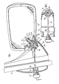
- a rear-view mirror has a bracket 10 mounted on the body 12 of a vehicle.
- the bracket 10 has a part-spherical portion 14 with a concave outer surface.
- a coupling member 16 in the form of a sphere, engages in the outer surface of the portion 14 and also with a corresponding spherical portion 18 of a mirror housing 20.
- a rod 22 of square cross-section extends through a square hole in a part-spherical washer 24 inside the housing 20, through circular hole 26 in the spherical portion 18 of the housing 20, through a square hole in the coupling member 16, through a circular hole 28 in the spherical portion 14 of the bracket 10 and finally through a square hole in a second part-spherical washer 30, which is inside the bracket 10.
- a compression spring 32 engages between the washer 24 and a nut 34 on the end of the rod so as to resiliently urge the various abuting part-spherical surfaces into engagement with one another.
- the part-spherical washer 30 has handle 36 extending from its periphery through a horizontal slot 38 into the interior of the vehicle. On its free end the handle 36 has a knob 40.
- the various square holes through which the rod 22 extends are a sliding fit on the rod 22 so as to inhibit relative angular movement.
- the two circular holes 26 and 28, in the housing 20 and the bracket 10 respectively are over-size so as to permit a limited amount of relative radial movement as well as allowing relative angular movement.
- the housing 20 is first adjusted so as to be set in about the required orientation by manually grasping the housing itself so as to move it relative to the coupling member 16.
- Final adjustment can be performed from inside the vehicle by manipulating the knob 40 of the handle 26. Twisting of the handle 36 substantially about its own axis (actually moving it along an arcuate path about the centre of the spherical coupling member (16) moves the housing 20 about a horizontal axis so as to adjust it in the vertical direction. Angular movement of the handle 36 about the axis of the rod 22 moves the housing 20 about such axis so as to adjust the orientation of the housing 20 in the horizontal direction.
- Figures 3 and 4 illustrate another embodiment of the invention comprising a mirror housing 50 and a bracket 52, the latter being mounted on the body 54 of a motor vehicle.
- the bracket 52 has projecting portion 56 with a concave part-spherical lower surface 58.
- Abutting the surface 58 is a hollow hemispherical member 60 having a projection 62 extending from the great circle periphery of the hemisphere through a horizontal slot 64 into the interior of the vehicle.
- a cranked handle 66 is secured to the end of the projection 62.
- a second hollow hemisphere 70 located with its plane surface abutting that of the hemisphere 60, has a projection 72 extending in substantially the opposite direction to the projection 62 and carrying the mirror housing 50.
- the plane surface of the hemisphere 70 has a ridge 74 arranged to engage in a complementary groove in the abutting plane surface of the hemisphere 60 in order to define a preferred orientation for the mirror housing 50 relative to the handle 66.
- a part-spherical washer 76 disposed with its concave surface in contact with the hemisphere 70 carries a cylindrical pocket 78 which extends into the space within the two hemispheres 60 and 70.
- the pocket 78 contains a compression spring 82 which abuts against a nut 84 which is screwed on to a bolt 86.
- the bolt 86 extends through a hole in the projection 56 on the bracket 52 and through a hole 88 in the hemisphere 60 before entering the inner end of the pocket 78.
- the spring 82 compresses the two hemispheres 60 and 70 between the part-spherical washer 76 and the hemispherical surface 58 of the projection 56 with a force which can be varied by varying the extent to which the nut 84 is screwed on to the bolt 86.
- the orientation of the mirror in the lateral direction can be adjusted by moving the handle 66 horizontally along the slot 64 so as to pivot the two hemispheres 60 and 70 about the bolt 86.
- Adjustment in the vertical direction can be effected by rotating the handle 66 about the axis of the projection 62 so as to cause a corresponding angular movement of the hemispheres 60 and 70, the holes 88 and 80 therein being sufficiently elongated to permit such angular movement through a few degrees.
- the ridge 74 becomes disengaged from its groove (increasing the compression of the spring 82) whereupon the hemisphere 70 can pivot about the bolt 86 relative to the hemisphere 60, the ridge 74 and its grooves ensuring that the mirror housing 50 can readily be restored to its previous position.
- connection between the mirror housing 50 and the projection 72 incorporates a projection 90 in the shape of a truncated pyramid which engages in a correspondingly shaped recess in the mirror housing 50.
- mirror housings for use on the left side and the right side of the vehicle respectively can be formed with their recesses for receiving the pyramid 90 at slightly different angles.
- the mirror illustrated in Figures 3 and 4 is suitable for mounting on a vehicle door below the bottom edge of the window.
- Figure 5 illustrates an alternative arrangement which is suitable for mounting above the level of the bottom edge of the window, for example, on a triangular panel, commonly called a "cheater", filling the bottom front corner of the window opening.
- Most of the components of the mirror illustrated in Figure 5 are identical with the corresponding components illustrated in Figures 3 and 4 and are denoted with the same reference numerals.
- the second hemisphere 70 of the mirror illustrated in Figures 3 and 4 is replaced by a second hemisphere 92 having a projection 94 which is directly attached to the side edge of the mirror housing 96. Provision for alternative mounting angles for left and right hand mirrors can be made by varying the position of the ridge 74.
Landscapes
- Engineering & Computer Science (AREA)
- Multimedia (AREA)
- Mechanical Engineering (AREA)
- Rear-View Mirror Devices That Are Mounted On The Exterior Of The Vehicle (AREA)
Claims (5)
Applications Claiming Priority (2)
| Application Number | Priority Date | Filing Date | Title |
|---|---|---|---|
| GB8113725 | 1981-05-02 | ||
| GB8113725 | 1981-05-02 |
Publications (2)
| Publication Number | Publication Date |
|---|---|
| EP0064335A1 EP0064335A1 (fr) | 1982-11-10 |
| EP0064335B1 true EP0064335B1 (fr) | 1985-07-17 |
Family
ID=10521586
Family Applications (1)
| Application Number | Title | Priority Date | Filing Date |
|---|---|---|---|
| EP19820301855 Expired EP0064335B1 (fr) | 1981-05-02 | 1982-04-07 | Miroir rétroviseur pour véhicules automobiles |
Country Status (3)
| Country | Link |
|---|---|
| EP (1) | EP0064335B1 (fr) |
| DE (1) | DE3264747D1 (fr) |
| MY (1) | MY8600339A (fr) |
Families Citing this family (7)
| Publication number | Priority date | Publication date | Assignee | Title |
|---|---|---|---|---|
| FR2554066B1 (fr) * | 1983-10-28 | 1989-03-10 | Britax Geco Sa | Systeme de construction de retroviseurs de vehicules |
| IT8453862V0 (it) * | 1984-09-27 | 1984-09-27 | Fiat Auto Spa | Specchio retrovisore esterno regolabile dall interno per autoveicoli |
| US4988068A (en) * | 1988-06-09 | 1991-01-29 | Murakami Kameido Co., Ltd. | Remote control mechanism |
| IT220764Z2 (it) * | 1990-12-21 | 1993-11-08 | Gilardini Spa | Specchio retrovisore per un veicolo. |
| JP3995742B2 (ja) * | 1996-11-28 | 2007-10-24 | 本田技研工業株式会社 | バックミラー支持構造 |
| US5946151A (en) * | 1997-03-17 | 1999-08-31 | Siegel-Robert, Inc. | Automobile pivotal mirror mounting assembly |
| JP2006168648A (ja) * | 2004-12-17 | 2006-06-29 | Murakami Corp | アウターミラー |
Family Cites Families (5)
| Publication number | Priority date | Publication date | Assignee | Title |
|---|---|---|---|---|
| GB813086A (en) * | 1956-09-17 | 1959-05-06 | Gen Motors Corp | Improvements in or relating to rear view mirrors for motor vehicles |
| DE2411319A1 (de) * | 1974-03-09 | 1975-09-11 | Volkswagenwerk Ag | Aussenspiegelanordnung fuer fahrzeuge |
| DE2431735A1 (de) * | 1974-07-02 | 1976-01-29 | Audi Nsu Auto Union Ag | Von innen einstellbarer aussenrueckspiegel |
| FR2405843A1 (fr) * | 1977-10-12 | 1979-05-11 | Bsg Int Ltd | Perfectionnements aux retroviseurs exterieurs commandes de l'interieur du vehicule |
| DE3010786C2 (de) * | 1980-04-25 | 1986-07-03 | Murakami Kaimeido Co., Ltd., Shizuoka | Fernsteuervorrichtung für ein Einstellteil, insbesondere zur Lageverstellung eines Rückspiegels an einem Kraftfahrzeug |
-
1982
- 1982-04-07 EP EP19820301855 patent/EP0064335B1/fr not_active Expired
- 1982-04-07 DE DE8282301855T patent/DE3264747D1/de not_active Expired
-
1986
- 1986-12-30 MY MY8600339A patent/MY8600339A/xx unknown
Also Published As
| Publication number | Publication date |
|---|---|
| MY8600339A (en) | 1986-12-31 |
| EP0064335A1 (fr) | 1982-11-10 |
| DE3264747D1 (en) | 1985-08-22 |
Similar Documents
| Publication | Publication Date | Title |
|---|---|---|
| US4506954A (en) | Motor-driven remote control mirror device with shaft portion pivot not coincident with shaft axis | |
| KR950002900B1 (ko) | 후방관찰용 거울을 원격제어하는 위치자동 조절 시스템 | |
| CA1325351C (fr) | Retroviseur de vehicule | |
| EP0272047B1 (fr) | Transmission vis-écrou pivotante | |
| EP0064335B1 (fr) | Miroir rétroviseur pour véhicules automobiles | |
| KR100743503B1 (ko) | 차량용 인사이드 리어뷰 미러장치 | |
| US4761717A (en) | Headlamp pivot assembly | |
| EP0177458B1 (fr) | Rétroviseur extérieur pour véhicule automobile | |
| EP1153794B1 (fr) | Dispositif de réglage d'angle de miroir | |
| US3782218A (en) | Adjustable and tiltable rearview mirror especially for passenger motor vehicles | |
| EP0276677A1 (fr) | Support de miroir pour un rétroviseur | |
| US4916589A (en) | Mounting structure for automobile lamp | |
| US4258894A (en) | Rear-view mirror for automotive vehicles | |
| EP0269081A1 (fr) | Dispositif de support pour un élément de miroir de rétroviseur | |
| EP0074753B1 (fr) | Rétroviseur pour véhicules automobiles | |
| EP0206758B1 (fr) | Rétroviseur de porte pour véhicule | |
| US3390588A (en) | Remote control mirror | |
| US4941639A (en) | Remotely controlled rearview mirror for motor vehicles | |
| EP0171906B1 (fr) | Rétroviseur extérieur pour véhicules | |
| US2942522A (en) | Rear view device | |
| US4828215A (en) | External rearview mirror for vehicles | |
| EP0186366A2 (fr) | Miroir rétroviseur pour véhicule | |
| EP0064815B1 (fr) | Miroir rétroviseur télécommandé | |
| JPH0911795A (ja) | 車両用アウトサイドミラー装置 | |
| JPH01226451A (ja) | バックミラー組立体 |
Legal Events
| Date | Code | Title | Description |
|---|---|---|---|
| PUAI | Public reference made under article 153(3) epc to a published international application that has entered the european phase |
Free format text: ORIGINAL CODE: 0009012 |
|
| AK | Designated contracting states |
Designated state(s): DE FR GB |
|
| 17P | Request for examination filed |
Effective date: 19830502 |
|
| GRAA | (expected) grant |
Free format text: ORIGINAL CODE: 0009210 |
|
| AK | Designated contracting states |
Designated state(s): DE FR GB |
|
| REF | Corresponds to: |
Ref document number: 3264747 Country of ref document: DE Date of ref document: 19850822 |
|
| ET | Fr: translation filed | ||
| PLBE | No opposition filed within time limit |
Free format text: ORIGINAL CODE: 0009261 |
|
| STAA | Information on the status of an ep patent application or granted ep patent |
Free format text: STATUS: NO OPPOSITION FILED WITHIN TIME LIMIT |
|
| 26N | No opposition filed | ||
| PGFP | Annual fee paid to national office [announced via postgrant information from national office to epo] |
Ref country code: GB Payment date: 19960329 Year of fee payment: 15 |
|
| PGFP | Annual fee paid to national office [announced via postgrant information from national office to epo] |
Ref country code: FR Payment date: 19960410 Year of fee payment: 15 |
|
| PGFP | Annual fee paid to national office [announced via postgrant information from national office to epo] |
Ref country code: DE Payment date: 19960418 Year of fee payment: 15 |
|
| PG25 | Lapsed in a contracting state [announced via postgrant information from national office to epo] |
Ref country code: GB Effective date: 19970407 |
|
| GBPC | Gb: european patent ceased through non-payment of renewal fee |
Effective date: 19970407 |
|
| PG25 | Lapsed in a contracting state [announced via postgrant information from national office to epo] |
Ref country code: FR Free format text: LAPSE BECAUSE OF NON-PAYMENT OF DUE FEES Effective date: 19971231 |
|
| PG25 | Lapsed in a contracting state [announced via postgrant information from national office to epo] |
Ref country code: DE Free format text: LAPSE BECAUSE OF NON-PAYMENT OF DUE FEES Effective date: 19980101 |
|
| REG | Reference to a national code |
Ref country code: FR Ref legal event code: ST |