EP0064335B1 - Rear-view mirror for motor vehicles - Google Patents
Rear-view mirror for motor vehicles Download PDFInfo
- Publication number
- EP0064335B1 EP0064335B1 EP19820301855 EP82301855A EP0064335B1 EP 0064335 B1 EP0064335 B1 EP 0064335B1 EP 19820301855 EP19820301855 EP 19820301855 EP 82301855 A EP82301855 A EP 82301855A EP 0064335 B1 EP0064335 B1 EP 0064335B1
- Authority
- EP
- European Patent Office
- Prior art keywords
- spherical
- coupling
- coupling member
- mirror housing
- bracket
- Prior art date
- Legal status (The legal status is an assumption and is not a legal conclusion. Google has not performed a legal analysis and makes no representation as to the accuracy of the status listed.)
- Expired
Links
Images

Classifications
-
- B—PERFORMING OPERATIONS; TRANSPORTING
- B60—VEHICLES IN GENERAL
- B60R—VEHICLES, VEHICLE FITTINGS, OR VEHICLE PARTS, NOT OTHERWISE PROVIDED FOR
- B60R1/00—Optical viewing arrangements; Real-time viewing arrangements for drivers or passengers using optical image capturing systems, e.g. cameras or video systems specially adapted for use in or on vehicles
- B60R1/02—Rear-view mirror arrangements
- B60R1/06—Rear-view mirror arrangements mounted on vehicle exterior
- B60R1/062—Rear-view mirror arrangements mounted on vehicle exterior with remote control for adjusting position
- B60R1/064—Rear-view mirror arrangements mounted on vehicle exterior with remote control for adjusting position by manually powered actuators
Landscapes
- Engineering & Computer Science (AREA)
- Multimedia (AREA)
- Mechanical Engineering (AREA)
- Rear-View Mirror Devices That Are Mounted On The Exterior Of The Vehicle (AREA)
Description
- This invention relates to an exterior rear-view mirror for a vehicle which is adjustable from the interior of the vehicle and which comprises a 5 bracket adapted to be secured to the vehicle and having a part-spherical surface, a mirror housing having a coupling surface, a coupling member having a first coupling surface of part-spherical shape of equal radius but opposite curvature to IC the part-spherical surface of the bracket and a second coupling surface shaped to engage with the coupling surface of the mirror housing so as to permit angular movement of the coupling member relative to the bracket about a pivot axis 1 through the centre of curvature of said part-spherical surface and angular movement of the mirror housing relative to the coupling member; resilient biasing means, arranged to bias the part-spherical surface of the bracket into
engagement 21 with the first coupling surface of the coupling member and to bias the coupling surface of the mirror housing into engagement with the second coupling surface of the coupling member and a handle permanently secured to saidcoupling 2, member for simultaneous angular movement therewith about said pivot axis. - A mirror of this type is disclosed in Patent Specification FR-A-2405843, movement of the coupling member relative to the bracket permit- 3 ting adjustment of the orientation of the mirror housing, and movement of the mirror housing relative to the coupling member allowing the housing to deflect in the event of impact. The coupling member increases the distance between 3 the mirror housing and the bracket, thus complicating the precautions neccessary to ensure that this deflection is not impeded by the means coupling the handle to the mirror housing.
- According to the characterising part of
claim 1, 4 the distance between the bracket and the mirror housing can be reduced. - According to the characterising part of
claim 2, the coupling means between the handle and the mirror housing can be located outside the mirror 4 housing. Consequently, the coupling means does not impede deflection of the mirror housing in the event of impact. Furthermore, the resilient biasing means can also be installed outside the mirror housing. 5 - An embodiment of the invention will now be described, by way of example, with reference to the accompanying drawings, in which:
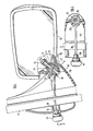
- Figure 1 is a transverse vertical sectional view of an exterior rear-view mirror in accordance with 5 one embodiment of the invention,
- Figure 2 is a cross-sectional view taken on the line 2-2 in Figure 1,
- Figure 3 is a plan view of an exterior rear-view mirror in accordance with another embodiment of 6 the invention,
- Figure 4 is a cross-sectional view taken on the line 4-4 in Figure 3, and
- Figure 5 is a cross-sectional view, similar to 6 Figure 4, of a further embodiment of the invention.
- As illustrated in Figures 1 and 2, a rear-view mirror has a
bracket 10 mounted on thebody 12 of a vehicle. Thebracket 10 has a part-spherical portion 14 with a concave outer surface. Acoupling member 16, in the form of a sphere, engages in the outer surface of the portion 14 and also with a correspondingspherical portion 18 of amirror housing 20. In order to hold the assembly together, arod 22 of square cross-section extends through a square hole in a part-spherical washer 24 inside thehousing 20, throughcircular hole 26 in thespherical portion 18 of thehousing 20, through a square hole in thecoupling member 16, through acircular hole 28 in the spherical portion 14 of thebracket 10 and finally through a square hole in a second part-spherical washer 30, which is inside thebracket 10. Acompression spring 32 engages between thewasher 24 and anut 34 on the end of the rod so as to resiliently urge the various abuting part-spherical surfaces into engagement with one another. - The part-
spherical washer 30 hashandle 36 extending from its periphery through ahorizontal slot 38 into the interior of the vehicle. On its free end thehandle 36 has aknob 40. - The various square holes through which the
rod 22 extends are a sliding fit on therod 22 so as to inhibit relative angular movement. However, the twocircular holes housing 20 and thebracket 10 respectively, are over-size so as to permit a limited amount of relative radial movement as well as allowing relative angular movement. - ' In use, the
housing 20 is first adjusted so as to be set in about the required orientation by manually grasping the housing itself so as to move it relative to thecoupling member 16. Final adjustment can be performed from inside the vehicle by manipulating theknob 40 of thehandle 26. Twisting of thehandle 36 substantially about its own axis (actually moving it along an arcuate path about the centre of the spherical coupling member (16) moves thehousing 20 about a horizontal axis so as to adjust it in the vertical direction. Angular movement of thehandle 36 about the axis of therod 22 moves thehousing 20 about such axis so as to adjust the orientation of thehousing 20 in the horizontal direction. - Figures 3 and 4 illustrate another embodiment of the invention comprising a
mirror housing 50 and abracket 52, the latter being mounted on thebody 54 of a motor vehicle. Thebracket 52 has projectingportion 56 with a concave part-sphericallower surface 58. Abutting thesurface 58 is a hollowhemispherical member 60 having aprojection 62 extending from the great circle periphery of the hemisphere through ahorizontal slot 64 into the interior of the vehicle. Acranked handle 66 is secured to the end of theprojection 62. - A second
hollow hemisphere 70, located with its plane surface abutting that of thehemisphere 60, has aprojection 72 extending in substantially the opposite direction to theprojection 62 and carrying themirror housing 50. The plane surface of thehemisphere 70 has aridge 74 arranged to engage in a complementary groove in the abutting plane surface of thehemisphere 60 in order to define a preferred orientation for themirror housing 50 relative to thehandle 66. - In order to maintain the two
hemispheres spherical washer 76 disposed with its concave surface in contact with thehemisphere 70 carries acylindrical pocket 78 which extends into the space within the twohemispheres pocket 78 contains acompression spring 82 which abuts against anut 84 which is screwed on to abolt 86. Thebolt 86 extends through a hole in theprojection 56 on thebracket 52 and through ahole 88 in thehemisphere 60 before entering the inner end of thepocket 78. Thus, thespring 82 compresses the twohemispheres spherical washer 76 and thehemispherical surface 58 of theprojection 56 with a force which can be varied by varying the extent to which thenut 84 is screwed on to thebolt 86. - In use, the orientation of the mirror in the lateral direction can be adjusted by moving the
handle 66 horizontally along theslot 64 so as to pivot the twohemispheres bolt 86. Adjustment in the vertical direction can be effected by rotating thehandle 66 about the axis of theprojection 62 so as to cause a corresponding angular movement of thehemispheres holes 88 and 80 therein being sufficiently elongated to permit such angular movement through a few degrees. - In the event of the
mirror housing 50 being subject to impact tending to fold it against the side of the vehicle, theridge 74 becomes disengaged from its groove (increasing the compression of the spring 82) whereupon thehemisphere 70 can pivot about thebolt 86 relative to thehemisphere 60, theridge 74 and its grooves ensuring that themirror housing 50 can readily be restored to its previous position. - In order to permit the same mechanism to be used for mirrors where the normally desired orientation relative to the
bracket 52 differs, for example left hand and right hand mirrors, the connection between themirror housing 50 and theprojection 72 incorporates aprojection 90 in the shape of a truncated pyramid which engages in a correspondingly shaped recess in themirror housing 50. With this arrangement, mirror housings for use on the left side and the right side of the vehicle respectively can be formed with their recesses for receiving thepyramid 90 at slightly different angles. - The mirror illustrated in Figures 3 and 4 is suitable for mounting on a vehicle door below the bottom edge of the window. Figure 5 illustrates an alternative arrangement which is suitable for mounting above the level of the bottom edge of the window, for example, on a triangular panel, commonly called a "cheater", filling the bottom front corner of the window opening. Most of the components of the mirror illustrated in Figure 5 are identical with the corresponding components illustrated in Figures 3 and 4 and are denoted with the same reference numerals. However, the
second hemisphere 70 of the mirror illustrated in Figures 3 and 4 is replaced by asecond hemisphere 92 having aprojection 94 which is directly attached to the side edge of themirror housing 96. Provision for alternative mounting angles for left and right hand mirrors can be made by varying the position of theridge 74.
Claims (5)
Applications Claiming Priority (2)
| Application Number | Priority Date | Filing Date | Title |
|---|---|---|---|
| GB8113725 | 1981-05-02 | ||
| GB8113725 | 1981-05-02 |
Publications (2)
| Publication Number | Publication Date |
|---|---|
| EP0064335A1 EP0064335A1 (en) | 1982-11-10 |
| EP0064335B1 true EP0064335B1 (en) | 1985-07-17 |
Family
ID=10521586
Family Applications (1)
| Application Number | Title | Priority Date | Filing Date |
|---|---|---|---|
| EP19820301855 Expired EP0064335B1 (en) | 1981-05-02 | 1982-04-07 | Rear-view mirror for motor vehicles |
Country Status (3)
| Country | Link |
|---|---|
| EP (1) | EP0064335B1 (en) |
| DE (1) | DE3264747D1 (en) |
| MY (1) | MY8600339A (en) |
Families Citing this family (7)
| Publication number | Priority date | Publication date | Assignee | Title |
|---|---|---|---|---|
| FR2554066B1 (en) * | 1983-10-28 | 1989-03-10 | Britax Geco Sa | VEHICLE MIRROR CONSTRUCTION SYSTEM |
| IT8453862V0 (en) * | 1984-09-27 | 1984-09-27 | Fiat Auto Spa | EXTERNAL REAR VIEW MIRROR ADJUSTABLE FROM THE INSIDE FOR VEHICLES |
| US4988068A (en) * | 1988-06-09 | 1991-01-29 | Murakami Kameido Co., Ltd. | Remote control mechanism |
| IT220764Z2 (en) * | 1990-12-21 | 1993-11-08 | Gilardini Spa | REAR-VIEW MIRROR FOR A VEHICLE. |
| JP3995742B2 (en) * | 1996-11-28 | 2007-10-24 | 本田技研工業株式会社 | Rearview mirror support structure |
| US5946151A (en) * | 1997-03-17 | 1999-08-31 | Siegel-Robert, Inc. | Automobile pivotal mirror mounting assembly |
| JP2006168648A (en) * | 2004-12-17 | 2006-06-29 | Murakami Corp | Outer mirror |
Family Cites Families (5)
| Publication number | Priority date | Publication date | Assignee | Title |
|---|---|---|---|---|
| GB813086A (en) * | 1956-09-17 | 1959-05-06 | Gen Motors Corp | Improvements in or relating to rear view mirrors for motor vehicles |
| DE2411319A1 (en) * | 1974-03-09 | 1975-09-11 | Volkswagenwerk Ag | External rear view mirror - has lever to transfer night and day positions remotely from car interior |
| DE2431735A1 (en) * | 1974-07-02 | 1976-01-29 | Audi Nsu Auto Union Ag | Remotely adjustable wing mirror - with adjustment control releasing friction spring within spherical pivot joint for fine adjustment |
| FR2405843A1 (en) * | 1977-10-12 | 1979-05-11 | Bsg Int Ltd | Adjustable exterior rear mirror for car - has ball jointed rods extending through body panel to be turned and locked in desired position |
| DE3010786C2 (en) * | 1980-04-25 | 1986-07-03 | Murakami Kaimeido Co., Ltd., Shizuoka | Remote control device for an adjustment part, in particular for adjusting the position of a rearview mirror on a motor vehicle |
-
1982
- 1982-04-07 EP EP19820301855 patent/EP0064335B1/en not_active Expired
- 1982-04-07 DE DE8282301855T patent/DE3264747D1/en not_active Expired
-
1986
- 1986-12-30 MY MY8600339A patent/MY8600339A/en unknown
Also Published As
| Publication number | Publication date |
|---|---|
| DE3264747D1 (en) | 1985-08-22 |
| MY8600339A (en) | 1986-12-31 |
| EP0064335A1 (en) | 1982-11-10 |
Similar Documents
| Publication | Publication Date | Title |
|---|---|---|
| US4506954A (en) | Motor-driven remote control mirror device with shaft portion pivot not coincident with shaft axis | |
| US5081546A (en) | Vehicle exterior mirror | |
| KR950002900B1 (en) | Memory positioning system for remote control rear-view mirror | |
| CA1325351C (en) | Automotive rear view mirror assembly | |
| EP0272047B1 (en) | A pivotable screw jack drive | |
| EP0064335B1 (en) | Rear-view mirror for motor vehicles | |
| KR100743503B1 (en) | Inside rearview mirror apparatus for vehicle | |
| EP0177458B1 (en) | External rear-view mirror for motor vehicles | |
| EP1153794B1 (en) | Mirror surface angle adjusting device | |
| US3782218A (en) | Adjustable and tiltable rearview mirror especially for passenger motor vehicles | |
| EP0276677A1 (en) | Holding device of a mirror element for a rearview mirror | |
| US4916589A (en) | Mounting structure for automobile lamp | |
| US4258894A (en) | Rear-view mirror for automotive vehicles | |
| EP0269081A1 (en) | Supporting device of a mirror element for a rearview mirror | |
| EP0074753B1 (en) | Rear-view mirror for motor vehicles | |
| EP0206758B1 (en) | Vehicle door mirrors | |
| US3390588A (en) | Remote control mirror | |
| US4941639A (en) | Remotely controlled rearview mirror for motor vehicles | |
| EP0171906B1 (en) | Exterior rearview mirrors for vehicles | |
| GB1578950A (en) | Rear view mirror assembly | |
| US4828215A (en) | External rearview mirror for vehicles | |
| EP0186366A2 (en) | Motor vehicle rearview mirror | |
| JPH0911795A (en) | Outside mirror device for vehicle | |
| JPH01226451A (en) | Back mirror assembly | |
| EP0099688A2 (en) | Rear view mirror |
Legal Events
| Date | Code | Title | Description |
|---|---|---|---|
| PUAI | Public reference made under article 153(3) epc to a published international application that has entered the european phase |
Free format text: ORIGINAL CODE: 0009012 |
|
| AK | Designated contracting states |
Designated state(s): DE FR GB |
|
| 17P | Request for examination filed |
Effective date: 19830502 |
|
| GRAA | (expected) grant |
Free format text: ORIGINAL CODE: 0009210 |
|
| AK | Designated contracting states |
Designated state(s): DE FR GB |
|
| REF | Corresponds to: |
Ref document number: 3264747 Country of ref document: DE Date of ref document: 19850822 |
|
| ET | Fr: translation filed | ||
| PLBE | No opposition filed within time limit |
Free format text: ORIGINAL CODE: 0009261 |
|
| STAA | Information on the status of an ep patent application or granted ep patent |
Free format text: STATUS: NO OPPOSITION FILED WITHIN TIME LIMIT |
|
| 26N | No opposition filed | ||
| PGFP | Annual fee paid to national office [announced via postgrant information from national office to epo] |
Ref country code: GB Payment date: 19960329 Year of fee payment: 15 |
|
| PGFP | Annual fee paid to national office [announced via postgrant information from national office to epo] |
Ref country code: FR Payment date: 19960410 Year of fee payment: 15 |
|
| PGFP | Annual fee paid to national office [announced via postgrant information from national office to epo] |
Ref country code: DE Payment date: 19960418 Year of fee payment: 15 |
|
| PG25 | Lapsed in a contracting state [announced via postgrant information from national office to epo] |
Ref country code: GB Effective date: 19970407 |
|
| GBPC | Gb: european patent ceased through non-payment of renewal fee |
Effective date: 19970407 |
|
| PG25 | Lapsed in a contracting state [announced via postgrant information from national office to epo] |
Ref country code: FR Free format text: LAPSE BECAUSE OF NON-PAYMENT OF DUE FEES Effective date: 19971231 |
|
| PG25 | Lapsed in a contracting state [announced via postgrant information from national office to epo] |
Ref country code: DE Free format text: LAPSE BECAUSE OF NON-PAYMENT OF DUE FEES Effective date: 19980101 |
|
| REG | Reference to a national code |
Ref country code: FR Ref legal event code: ST |