EP0063679A2 - Dispositif de perçage pour la réalisation de trous avec des cavités au fond des trous - Google Patents
Dispositif de perçage pour la réalisation de trous avec des cavités au fond des trous Download PDFInfo
- Publication number
- EP0063679A2 EP0063679A2 EP82101316A EP82101316A EP0063679A2 EP 0063679 A2 EP0063679 A2 EP 0063679A2 EP 82101316 A EP82101316 A EP 82101316A EP 82101316 A EP82101316 A EP 82101316A EP 0063679 A2 EP0063679 A2 EP 0063679A2
- Authority
- EP
- European Patent Office
- Prior art keywords
- drill
- drilling
- stop plate
- borehole
- bell
- Prior art date
- Legal status (The legal status is an assumption and is not a legal conclusion. Google has not performed a legal analysis and makes no representation as to the accuracy of the status listed.)
- Granted
Links
- 238000005553 drilling Methods 0.000 title claims abstract description 39
- 238000005520 cutting process Methods 0.000 title claims abstract description 4
- 238000004519 manufacturing process Methods 0.000 claims description 2
- 239000000428 dust Substances 0.000 description 5
- 238000004873 anchoring Methods 0.000 description 4
- 239000002184 metal Substances 0.000 description 2
- 229910000760 Hardened steel Inorganic materials 0.000 description 1
- 230000006978 adaptation Effects 0.000 description 1
- 230000015572 biosynthetic process Effects 0.000 description 1
- 238000004140 cleaning Methods 0.000 description 1
- 230000000694 effects Effects 0.000 description 1
- 238000000034 method Methods 0.000 description 1
- 230000002093 peripheral effect Effects 0.000 description 1
- 238000003756 stirring Methods 0.000 description 1
Images
Classifications
-
- B—PERFORMING OPERATIONS; TRANSPORTING
- B25—HAND TOOLS; PORTABLE POWER-DRIVEN TOOLS; MANIPULATORS
- B25F—COMBINATION OR MULTI-PURPOSE TOOLS NOT OTHERWISE PROVIDED FOR; DETAILS OR COMPONENTS OF PORTABLE POWER-DRIVEN TOOLS NOT PARTICULARLY RELATED TO THE OPERATIONS PERFORMED AND NOT OTHERWISE PROVIDED FOR
- B25F3/00—Associations of tools for different working operations with one portable power-drive means; Adapters therefor
-
- B—PERFORMING OPERATIONS; TRANSPORTING
- B23—MACHINE TOOLS; METAL-WORKING NOT OTHERWISE PROVIDED FOR
- B23B—TURNING; BORING
- B23B51/00—Tools for drilling machines
- B23B51/0018—Drills for enlarging a hole
- B23B51/0027—Drills for enlarging a hole by tool swivelling
-
- B—PERFORMING OPERATIONS; TRANSPORTING
- B25—HAND TOOLS; PORTABLE POWER-DRIVEN TOOLS; MANIPULATORS
- B25D—PERCUSSIVE TOOLS
- B25D17/00—Details of, or accessories for, portable power-driven percussive tools
- B25D17/005—Attachments or adapters placed between tool and hammer
Definitions
- the invention relates to a drilling device intended for the production of boreholes with an undercut, consisting of a drill having a drilling plate with radially projecting side cutting edges, a drill receptacle with a stop collar, which is supported in a trough of a stop plate placed over the drill shaft to form a pivot bearing, and a drilling bell that can be connected to the stop plate and is provided with a suction nozzle.
- Such a drilling device makes it possible in a simple manner to produce bores with an undercut in the depth of the borehole by pivoting the drill when the desired borehole depth is reached.
- the stop plate absorbs the contact pressure generated during drilling and swiveling.
- a dowel is inserted into the borehole prepared in this way, which is designed in such a way that it spreads out in the undercut of the borehole. This creates an interlocking anchoring, the high holding value of which is guaranteed even if the borehole is larger or if the borehole is subsequently enlarged due to crack formation.
- hammering tools which can be clamped in rotary hammers and impact drills are known, among other things.
- the disadvantage of such impact tools is that either a second hammer drill for the impact tool or a replacement of the drill with the impact tool is required.
- the invention has for its object to provide a drilling device in which this disadvantage no longer occurs.
- a cover disk can be placed over the end face of the drilling bell formed by the stop plate, on which a tubular impact tool which can be put over the drill is arranged, the end face of which is adapted to the dowel to be anchored in the borehole.
- the cover disk provided with the driving tool is placed on the end face of the drilling bell, the bore of the driving tool being larger in diameter than the width of the drill plate and longer than the part of the drill protruding from the front face of the drilling bell.
- the outer diameter of the anchor corresponds to the borehole diameter and thus the width of the drill plate.
- the impact tool can be supported directly on the stop plate.
- the impact tool preferably consists of a hardened steel sleeve.
- a suction nozzle fitting into the borehole can be placed on the impact tool. Due to the tubular design of the hammering tool, it is possible, via the hammering tool and the suction nozzle placed on the hammering tool, to suck the drilling dust out of the borehole by means of a suction device connected to the suction nozzle of the drilling bell. This means that it is not necessary to unclamp the drilling device even for suction. In addition, the air flow passed through the drill cools the drill after each drilling operation.
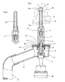
- the drill consists of the drill shaft] and the drill plate 2 connected to it.
- the drill shaft 1 is provided with grooves 3 that spiral around the shaft.
- the drill holder 4 is provided with the hemispherical stop collar 6.
- This stop collar 6 is supported in a trough 7 which on the surface of the masonry 8 Drill overlying stop plate 9. This results in a pivot bearing which makes it possible to pivot the drill out during the drilling process and to form the undercut 10 of the borehole 11 by stirring.
- the part of the stop plate 9 which carries the trough 7 is preferably hardened and embedded in a metal disk 9 a. For centering and holding the stop plate 9, this has a sleeve-shaped centering projection 12 which engages in the borehole 11.
- the stop plate 9 is connected via a bayonet lock, pin connection, screw connection or the like to the drilling bell 13, which can be seen with a laterally protruding suction nozzle 14 designed as a handle.
- the hose 15 of a suction device is connected to this suction nozzle 14.
- the cover disk 18 provided with the drive-in tool 17 is placed on the end face of the drilling bell 13 and for this purpose has a flange 19 that extends over the peripheral surface of the drilling bell.
- the mounting of the wrapping tool 17 in the cover plate 18 is designed so that the hardened wrapping tool is supported directly on the metal stop plate 9.
- the bore diameter of the driving tool 17 is slightly larger than the width of the drilling plate 2, so that the driving tool can be placed over the drill.
- the end face 17 a of the driving tool 17 abutting on the dowel sleeve is reduced in diameter in adaptation to the dimensions of the dowel sleeve.
- the impact action of the impact drill 2Q is transmitted to the dowel sleeve via the impact tool 17, the stop plate 9 and the drill receptacle 4.
- Sliding the expansion lamellae 16 a onto the cone of the expansion body 21 seated on the bottom of the borehole is spread out in the undercut 10 of the borehole 11.
- a suction nozzle 22 which fits into the borehole 11 is placed on the impact tool 17 according to FIG. 2 and is inserted into the borehole when the suction device is switched on.
- the drilling dust is sucked off via the suction nozzle 22, the tubular impact tool 17, the drilling bell 13 and the suction nozzle 14 arranged on the drilling bell.
Landscapes
- Engineering & Computer Science (AREA)
- Mechanical Engineering (AREA)
- Processing Of Stones Or Stones Resemblance Materials (AREA)
- Perforating, Stamping-Out Or Severing By Means Other Than Cutting (AREA)
- Earth Drilling (AREA)
- Drilling And Boring (AREA)
- Electrical Discharge Machining, Electrochemical Machining, And Combined Machining (AREA)
- Crushing And Grinding (AREA)
- Cylinder Crankcases Of Internal Combustion Engines (AREA)
- Apparatus For Radiation Diagnosis (AREA)
- Drilling Tools (AREA)
Priority Applications (1)
| Application Number | Priority Date | Filing Date | Title |
|---|---|---|---|
| AT82101316T ATE15005T1 (de) | 1981-04-18 | 1982-02-20 | Bohrvorrichtung zur herstellung von bohrloechern mit hinterschneidung. |
Applications Claiming Priority (2)
| Application Number | Priority Date | Filing Date | Title |
|---|---|---|---|
| DE3115815 | 1981-04-18 | ||
| DE19813115815 DE3115815A1 (de) | 1981-04-18 | 1981-04-18 | Bohrvorrichtung zur herstellung von bohrloechern mit hinterschneidung |
Publications (3)
| Publication Number | Publication Date |
|---|---|
| EP0063679A2 true EP0063679A2 (fr) | 1982-11-03 |
| EP0063679A3 EP0063679A3 (en) | 1983-07-27 |
| EP0063679B1 EP0063679B1 (fr) | 1985-08-21 |
Family
ID=6130505
Family Applications (1)
| Application Number | Title | Priority Date | Filing Date |
|---|---|---|---|
| EP82101316A Expired EP0063679B1 (fr) | 1981-04-18 | 1982-02-20 | Dispositif de perçage pour la réalisation de trous avec des cavités au fond des trous |
Country Status (10)
| Country | Link |
|---|---|
| EP (1) | EP0063679B1 (fr) |
| JP (1) | JPS5919803B2 (fr) |
| AT (1) | ATE15005T1 (fr) |
| BR (1) | BR8202199A (fr) |
| DE (1) | DE3115815A1 (fr) |
| DK (1) | DK150729C (fr) |
| ES (1) | ES264494Y (fr) |
| GR (1) | GR75130B (fr) |
| HU (1) | HU186924B (fr) |
| YU (1) | YU44420B (fr) |
Cited By (3)
| Publication number | Priority date | Publication date | Assignee | Title |
|---|---|---|---|---|
| EP0392201A2 (fr) * | 1989-04-14 | 1990-10-17 | fischerwerke Artur Fischer GmbH & Co. KG | Outil pour enfoncer des boulons pour ancrage |
| EP0416182A1 (fr) * | 1989-09-08 | 1991-03-13 | Kabushiki Kaisha Miyanaga | Outil pour la mise en place de douilles d'ancrage |
| EP0426918A1 (fr) * | 1989-11-09 | 1991-05-15 | Louis N. Giannuzzi | Outil automatique pour fixation des boulons de maçonnerie |
Families Citing this family (8)
| Publication number | Priority date | Publication date | Assignee | Title |
|---|---|---|---|---|
| DE3522255A1 (de) * | 1985-06-21 | 1987-01-02 | Fischer Artur Dr H C | In einen bohrhammer bzw. schlagbohrmaschine einspannbare vorrichtung |
| DE3803708A1 (de) * | 1988-02-08 | 1989-08-17 | Fischer Artur Werke Gmbh | Montagevorrichtung fuer schlagbohrmaschinen |
| DE3916611A1 (de) * | 1989-05-22 | 1990-11-29 | Fischer Artur Werke Gmbh | Eintreibvorrichtung fuer einschlaganker mit spreizhuelse |
| DE4132228A1 (de) * | 1991-09-27 | 1993-04-01 | Fischer Artur Werke Gmbh | Bohrvorrichtung zur herstellung von bohrloechern mit hinterschneidung |
| DE4133848A1 (de) * | 1991-10-12 | 1993-04-15 | Fischer Artur Werke Gmbh | Bohrer zur herstellung von bohrloechern mit hinterschneidungen |
| DE102006037881A1 (de) * | 2006-08-11 | 2008-02-14 | Fischerwerke Artur Fischer Gmbh & Co. Kg | Werkzeug zum Herstellen eines Sackloches mit konischer Hinterschneidung |
| CN104107937A (zh) * | 2013-04-19 | 2014-10-22 | 苏州文鼎模具有限公司 | 一种可更换钻孔刃的阶梯钻 |
| JP7049873B2 (ja) * | 2018-03-20 | 2022-04-07 | 株式会社マキタ | 吸塵ビット及び回転打撃工具 |
Citations (1)
| Publication number | Priority date | Publication date | Assignee | Title |
|---|---|---|---|---|
| CH619879A5 (fr) * | 1976-02-13 | 1980-10-31 | Skil Nederland Nv |
-
1981
- 1981-04-18 DE DE19813115815 patent/DE3115815A1/de not_active Withdrawn
- 1981-12-23 GR GR67583A patent/GR75130B/el unknown
-
1982
- 1982-02-20 EP EP82101316A patent/EP0063679B1/fr not_active Expired
- 1982-02-20 AT AT82101316T patent/ATE15005T1/de not_active IP Right Cessation
- 1982-04-02 DK DK151782A patent/DK150729C/da not_active IP Right Cessation
- 1982-04-02 YU YU745/82A patent/YU44420B/xx unknown
- 1982-04-13 ES ES1982264494U patent/ES264494Y/es not_active Expired
- 1982-04-16 HU HU821180A patent/HU186924B/hu unknown
- 1982-04-16 JP JP57062669A patent/JPS5919803B2/ja not_active Expired
- 1982-04-16 BR BR8202199A patent/BR8202199A/pt unknown
Patent Citations (1)
| Publication number | Priority date | Publication date | Assignee | Title |
|---|---|---|---|---|
| CH619879A5 (fr) * | 1976-02-13 | 1980-10-31 | Skil Nederland Nv |
Cited By (5)
| Publication number | Priority date | Publication date | Assignee | Title |
|---|---|---|---|---|
| EP0392201A2 (fr) * | 1989-04-14 | 1990-10-17 | fischerwerke Artur Fischer GmbH & Co. KG | Outil pour enfoncer des boulons pour ancrage |
| EP0392201A3 (fr) * | 1989-04-14 | 1992-01-22 | fischerwerke Artur Fischer GmbH & Co. KG | Outil pour enfoncer des boulons pour ancrage |
| EP0416182A1 (fr) * | 1989-09-08 | 1991-03-13 | Kabushiki Kaisha Miyanaga | Outil pour la mise en place de douilles d'ancrage |
| US5050286A (en) * | 1989-09-08 | 1991-09-24 | Kabushiki Kaisha Miyanaga | Driving mechanism for anchor |
| EP0426918A1 (fr) * | 1989-11-09 | 1991-05-15 | Louis N. Giannuzzi | Outil automatique pour fixation des boulons de maçonnerie |
Also Published As
| Publication number | Publication date |
|---|---|
| JPS5919803B2 (ja) | 1984-05-09 |
| YU74582A (en) | 1986-06-30 |
| DE3115815A1 (de) | 1982-12-30 |
| DK150729C (da) | 1987-12-07 |
| BR8202199A (pt) | 1983-03-29 |
| GR75130B (fr) | 1984-07-13 |
| YU44420B (en) | 1990-08-31 |
| ES264494Y (es) | 1983-05-16 |
| EP0063679A3 (en) | 1983-07-27 |
| EP0063679B1 (fr) | 1985-08-21 |
| ES264494U (es) | 1982-11-16 |
| JPS57181817A (en) | 1982-11-09 |
| ATE15005T1 (de) | 1985-09-15 |
| DK151782A (da) | 1982-10-19 |
| HU186924B (en) | 1985-10-28 |
| DK150729B (da) | 1987-06-09 |
Similar Documents
| Publication | Publication Date | Title |
|---|---|---|
| EP0044386B1 (fr) | Dispositif de perçage en vue de percer un trou présentant une partie détalonnée | |
| EP0540841B1 (fr) | Dispostif de perçage à faire des trous à chambrage | |
| DE3819833C2 (de) | Dübelbohrer | |
| EP0698436B1 (fr) | Dispositif de forage à fabriquer des trous avec chambrage | |
| EP0063679B1 (fr) | Dispositif de perçage pour la réalisation de trous avec des cavités au fond des trous | |
| DE19810192A1 (de) | Bohrwerkzeug | |
| DE4014224A1 (de) | Vorrichtung zur herstellung von bohrloechern mit hinterschneidung | |
| DE102007060469B4 (de) | Führungsvorrichtung eines Bohrers | |
| DE2731901A1 (de) | Hinterschnitt-bohrwerkzeug | |
| EP0336182A2 (fr) | Dispositif de perçage pour l'usinage de chambrages dans des trous cylindriques | |
| EP0475891B1 (fr) | Méthode et moyen à usiner des trous | |
| EP0139866B1 (fr) | Dispositif de forage pour la fabrication de trous avec contre-dépouilles | |
| EP0347556A1 (fr) | Outil de forage pour la fabrication de trous à chambres | |
| EP0302202A2 (fr) | Outil pour la pose d'éléments de fixation | |
| EP0408860B1 (fr) | Dispositif pour fabriquer un chambrage dans un trou foré | |
| DE3605204A1 (de) | Vorrichtung zum absaugen von bohrmehl | |
| EP0791423B1 (fr) | Dispositif porte-foret avec un foret | |
| DE2652366A1 (de) | Hinterschnitt-bohrwerkzeug | |
| EP0038917B1 (fr) | Unité de perçage destinée à fabriquer des trous | |
| DE3803708A1 (de) | Montagevorrichtung fuer schlagbohrmaschinen | |
| DE3423633A1 (de) | Bohrvorrichtung zur herstellung von bohrloechern mit hinterschneidung | |
| EP0171521B1 (fr) | Dispositif de forage pour usiner des trous avec des chambrages à des niveaux différents | |
| DE3903369A1 (de) | Bohrvorrichtung zur herstellung von bohrloechern mit hinterschneidung | |
| DE3314422A1 (de) | Schlagbohrwerkzeug-kombination | |
| DE2227065C3 (de) | Vorrichtung zum Entgraten oder Ansenken der Kanten von Durchgangsbohrungen |
Legal Events
| Date | Code | Title | Description |
|---|---|---|---|
| PUAI | Public reference made under article 153(3) epc to a published international application that has entered the european phase |
Free format text: ORIGINAL CODE: 0009012 |
|
| AK | Designated contracting states |
Designated state(s): AT BE CH FR GB IT NL SE |
|
| 17P | Request for examination filed |
Effective date: 19830308 |
|
| PUAL | Search report despatched |
Free format text: ORIGINAL CODE: 0009013 |
|
| AK | Designated contracting states |
Designated state(s): AT BE CH FR GB IT LI NL SE |
|
| ITF | It: translation for a ep patent filed | ||
| GRAA | (expected) grant |
Free format text: ORIGINAL CODE: 0009210 |
|
| AK | Designated contracting states |
Designated state(s): AT BE CH FR GB IT LI NL SE |
|
| REF | Corresponds to: |
Ref document number: 15005 Country of ref document: AT Date of ref document: 19850915 Kind code of ref document: T |
|
| ET | Fr: translation filed | ||
| BECH | Be: change of holder |
Free format text: 850821 *FISCHER-WERKE ARTUR FISCHER G.M.B.H. |
|
| PLBE | No opposition filed within time limit |
Free format text: ORIGINAL CODE: 0009261 |
|
| STAA | Information on the status of an ep patent application or granted ep patent |
Free format text: STATUS: NO OPPOSITION FILED WITHIN TIME LIMIT |
|
| REG | Reference to a national code |
Ref country code: CH Ref legal event code: PUE Owner name: FISCHER-WERKE ARTUR FISCHER GMBH & CO. KG |
|
| 26N | No opposition filed | ||
| ITPR | It: changes in ownership of a european patent |
Owner name: CESSIONE;FISCHER WERKE ARTUR FISCHER GMBH & CO. KG |
|
| REG | Reference to a national code |
Ref country code: FR Ref legal event code: TP |
|
| NLS | Nl: assignments of ep-patents |
Owner name: FISCHER-WERKE ARTUR FISCHER GMBH & CO. KG. TE WALD |
|
| PG25 | Lapsed in a contracting state [announced via postgrant information from national office to epo] |
Ref country code: SE Effective date: 19880221 |
|
| BERE | Be: lapsed |
Owner name: FISCHER-WERKE ARTUR FISCHER G.M.B.H. Effective date: 19880228 |
|
| PGFP | Annual fee paid to national office [announced via postgrant information from national office to epo] |
Ref country code: GB Payment date: 19890131 Year of fee payment: 8 |
|
| PGFP | Annual fee paid to national office [announced via postgrant information from national office to epo] |
Ref country code: AT Payment date: 19890220 Year of fee payment: 8 |
|
| PGFP | Annual fee paid to national office [announced via postgrant information from national office to epo] |
Ref country code: CH Payment date: 19890223 Year of fee payment: 8 |
|
| ITTA | It: last paid annual fee | ||
| PG25 | Lapsed in a contracting state [announced via postgrant information from national office to epo] |
Ref country code: FR Effective date: 19890228 Ref country code: BE Effective date: 19890228 |
|
| PGFP | Annual fee paid to national office [announced via postgrant information from national office to epo] |
Ref country code: NL Payment date: 19890228 Year of fee payment: 8 |
|
| PG25 | Lapsed in a contracting state [announced via postgrant information from national office to epo] |
Ref country code: GB Effective date: 19900220 Ref country code: AT Effective date: 19900220 |
|
| PG25 | Lapsed in a contracting state [announced via postgrant information from national office to epo] |
Ref country code: LI Effective date: 19900228 Ref country code: CH Effective date: 19900228 |
|
| PG25 | Lapsed in a contracting state [announced via postgrant information from national office to epo] |
Ref country code: NL Effective date: 19900901 |
|
| NLV4 | Nl: lapsed or anulled due to non-payment of the annual fee | ||
| GBPC | Gb: european patent ceased through non-payment of renewal fee | ||
| REG | Reference to a national code |
Ref country code: CH Ref legal event code: PL |
|
| REG | Reference to a national code |
Ref country code: FR Ref legal event code: ST |
|
| EUG | Se: european patent has lapsed |
Ref document number: 82101316.6 Effective date: 19880927 |