EP0063060B1 - Tête pour l'extrusion d'une paraison tubulaire à au moins une couche de matière - Google Patents
Tête pour l'extrusion d'une paraison tubulaire à au moins une couche de matière Download PDFInfo
- Publication number
- EP0063060B1 EP0063060B1 EP82400443A EP82400443A EP0063060B1 EP 0063060 B1 EP0063060 B1 EP 0063060B1 EP 82400443 A EP82400443 A EP 82400443A EP 82400443 A EP82400443 A EP 82400443A EP 0063060 B1 EP0063060 B1 EP 0063060B1
- Authority
- EP
- European Patent Office
- Prior art keywords
- ring
- bushing
- head according
- extrusion head
- adjustment
- Prior art date
- Legal status (The legal status is an assumption and is not a legal conclusion. Google has not performed a legal analysis and makes no representation as to the accuracy of the status listed.)
- Expired
Links
- 239000000463 material Substances 0.000 title claims description 25
- 238000001125 extrusion Methods 0.000 claims description 37
- 230000000295 complement effect Effects 0.000 claims description 7
- 230000010355 oscillation Effects 0.000 claims description 3
- 230000002787 reinforcement Effects 0.000 claims 2
- 239000010410 layer Substances 0.000 description 21
- 229920000642 polymer Polymers 0.000 description 4
- 238000004519 manufacturing process Methods 0.000 description 3
- 230000015572 biosynthetic process Effects 0.000 description 2
- 230000001627 detrimental effect Effects 0.000 description 2
- 239000007789 gas Substances 0.000 description 2
- 239000002356 single layer Substances 0.000 description 2
- 239000004952 Polyamide Substances 0.000 description 1
- 239000004698 Polyethylene Substances 0.000 description 1
- 239000012141 concentrate Substances 0.000 description 1
- 230000007547 defect Effects 0.000 description 1
- 230000002950 deficient Effects 0.000 description 1
- 230000003111 delayed effect Effects 0.000 description 1
- 238000009826 distribution Methods 0.000 description 1
- 230000000694 effects Effects 0.000 description 1
- 238000010101 extrusion blow moulding Methods 0.000 description 1
- 235000013305 food Nutrition 0.000 description 1
- 238000009432 framing Methods 0.000 description 1
- 238000003754 machining Methods 0.000 description 1
- 238000000034 method Methods 0.000 description 1
- 238000012544 monitoring process Methods 0.000 description 1
- 238000005192 partition Methods 0.000 description 1
- 230000002093 peripheral effect Effects 0.000 description 1
- 239000004033 plastic Substances 0.000 description 1
- 229920003023 plastic Polymers 0.000 description 1
- 229920002647 polyamide Polymers 0.000 description 1
- -1 polyethylene Polymers 0.000 description 1
- 229920000573 polyethylene Polymers 0.000 description 1
- 230000002035 prolonged effect Effects 0.000 description 1
- 238000011084 recovery Methods 0.000 description 1
- 239000012779 reinforcing material Substances 0.000 description 1
- 230000035939 shock Effects 0.000 description 1
- 238000009827 uniform distribution Methods 0.000 description 1
Images

Classifications
-
- B—PERFORMING OPERATIONS; TRANSPORTING
- B29—WORKING OF PLASTICS; WORKING OF SUBSTANCES IN A PLASTIC STATE IN GENERAL
- B29C—SHAPING OR JOINING OF PLASTICS; SHAPING OF MATERIAL IN A PLASTIC STATE, NOT OTHERWISE PROVIDED FOR; AFTER-TREATMENT OF THE SHAPED PRODUCTS, e.g. REPAIRING
- B29C48/00—Extrusion moulding, i.e. expressing the moulding material through a die or nozzle which imparts the desired form; Apparatus therefor
- B29C48/25—Component parts, details or accessories; Auxiliary operations
- B29C48/30—Extrusion nozzles or dies
- B29C48/32—Extrusion nozzles or dies with annular openings, e.g. for forming tubular articles
- B29C48/34—Cross-head annular extrusion nozzles, i.e. for simultaneously receiving moulding material and the preform to be coated
-
- B—PERFORMING OPERATIONS; TRANSPORTING
- B29—WORKING OF PLASTICS; WORKING OF SUBSTANCES IN A PLASTIC STATE IN GENERAL
- B29C—SHAPING OR JOINING OF PLASTICS; SHAPING OF MATERIAL IN A PLASTIC STATE, NOT OTHERWISE PROVIDED FOR; AFTER-TREATMENT OF THE SHAPED PRODUCTS, e.g. REPAIRING
- B29C48/00—Extrusion moulding, i.e. expressing the moulding material through a die or nozzle which imparts the desired form; Apparatus therefor
- B29C48/03—Extrusion moulding, i.e. expressing the moulding material through a die or nozzle which imparts the desired form; Apparatus therefor characterised by the shape of the extruded material at extrusion
- B29C48/09—Articles with cross-sections having partially or fully enclosed cavities, e.g. pipes or channels
- B29C48/10—Articles with cross-sections having partially or fully enclosed cavities, e.g. pipes or channels flexible, e.g. blown foils
-
- B—PERFORMING OPERATIONS; TRANSPORTING
- B29—WORKING OF PLASTICS; WORKING OF SUBSTANCES IN A PLASTIC STATE IN GENERAL
- B29C—SHAPING OR JOINING OF PLASTICS; SHAPING OF MATERIAL IN A PLASTIC STATE, NOT OTHERWISE PROVIDED FOR; AFTER-TREATMENT OF THE SHAPED PRODUCTS, e.g. REPAIRING
- B29C48/00—Extrusion moulding, i.e. expressing the moulding material through a die or nozzle which imparts the desired form; Apparatus therefor
- B29C48/16—Articles comprising two or more components, e.g. co-extruded layers
- B29C48/18—Articles comprising two or more components, e.g. co-extruded layers the components being layers
- B29C48/21—Articles comprising two or more components, e.g. co-extruded layers the components being layers the layers being joined at their surfaces
-
- B—PERFORMING OPERATIONS; TRANSPORTING
- B29—WORKING OF PLASTICS; WORKING OF SUBSTANCES IN A PLASTIC STATE IN GENERAL
- B29C—SHAPING OR JOINING OF PLASTICS; SHAPING OF MATERIAL IN A PLASTIC STATE, NOT OTHERWISE PROVIDED FOR; AFTER-TREATMENT OF THE SHAPED PRODUCTS, e.g. REPAIRING
- B29C48/00—Extrusion moulding, i.e. expressing the moulding material through a die or nozzle which imparts the desired form; Apparatus therefor
- B29C48/25—Component parts, details or accessories; Auxiliary operations
- B29C48/30—Extrusion nozzles or dies
- B29C48/32—Extrusion nozzles or dies with annular openings, e.g. for forming tubular articles
- B29C48/325—Extrusion nozzles or dies with annular openings, e.g. for forming tubular articles being adjustable, i.e. having adjustable exit sections
-
- B—PERFORMING OPERATIONS; TRANSPORTING
- B29—WORKING OF PLASTICS; WORKING OF SUBSTANCES IN A PLASTIC STATE IN GENERAL
- B29C—SHAPING OR JOINING OF PLASTICS; SHAPING OF MATERIAL IN A PLASTIC STATE, NOT OTHERWISE PROVIDED FOR; AFTER-TREATMENT OF THE SHAPED PRODUCTS, e.g. REPAIRING
- B29C48/00—Extrusion moulding, i.e. expressing the moulding material through a die or nozzle which imparts the desired form; Apparatus therefor
- B29C48/25—Component parts, details or accessories; Auxiliary operations
- B29C48/30—Extrusion nozzles or dies
- B29C48/32—Extrusion nozzles or dies with annular openings, e.g. for forming tubular articles
- B29C48/335—Multiple annular extrusion nozzles in coaxial arrangement, e.g. for making multi-layered tubular articles
- B29C48/336—Multiple annular extrusion nozzles in coaxial arrangement, e.g. for making multi-layered tubular articles the components merging one by one down streams in the die
- B29C48/3363—Multiple annular extrusion nozzles in coaxial arrangement, e.g. for making multi-layered tubular articles the components merging one by one down streams in the die using a layered die, e.g. stacked discs
-
- B—PERFORMING OPERATIONS; TRANSPORTING
- B29—WORKING OF PLASTICS; WORKING OF SUBSTANCES IN A PLASTIC STATE IN GENERAL
- B29C—SHAPING OR JOINING OF PLASTICS; SHAPING OF MATERIAL IN A PLASTIC STATE, NOT OTHERWISE PROVIDED FOR; AFTER-TREATMENT OF THE SHAPED PRODUCTS, e.g. REPAIRING
- B29C48/00—Extrusion moulding, i.e. expressing the moulding material through a die or nozzle which imparts the desired form; Apparatus therefor
- B29C48/25—Component parts, details or accessories; Auxiliary operations
- B29C48/92—Measuring, controlling or regulating
-
- B—PERFORMING OPERATIONS; TRANSPORTING
- B29—WORKING OF PLASTICS; WORKING OF SUBSTANCES IN A PLASTIC STATE IN GENERAL
- B29C—SHAPING OR JOINING OF PLASTICS; SHAPING OF MATERIAL IN A PLASTIC STATE, NOT OTHERWISE PROVIDED FOR; AFTER-TREATMENT OF THE SHAPED PRODUCTS, e.g. REPAIRING
- B29C2948/00—Indexing scheme relating to extrusion moulding
- B29C2948/92—Measuring, controlling or regulating
- B29C2948/92504—Controlled parameter
- B29C2948/92571—Position, e.g. linear or angular
-
- B—PERFORMING OPERATIONS; TRANSPORTING
- B29—WORKING OF PLASTICS; WORKING OF SUBSTANCES IN A PLASTIC STATE IN GENERAL
- B29C—SHAPING OR JOINING OF PLASTICS; SHAPING OF MATERIAL IN A PLASTIC STATE, NOT OTHERWISE PROVIDED FOR; AFTER-TREATMENT OF THE SHAPED PRODUCTS, e.g. REPAIRING
- B29C2948/00—Indexing scheme relating to extrusion moulding
- B29C2948/92—Measuring, controlling or regulating
- B29C2948/92504—Controlled parameter
- B29C2948/92609—Dimensions
- B29C2948/92647—Thickness
-
- B—PERFORMING OPERATIONS; TRANSPORTING
- B29—WORKING OF PLASTICS; WORKING OF SUBSTANCES IN A PLASTIC STATE IN GENERAL
- B29C—SHAPING OR JOINING OF PLASTICS; SHAPING OF MATERIAL IN A PLASTIC STATE, NOT OTHERWISE PROVIDED FOR; AFTER-TREATMENT OF THE SHAPED PRODUCTS, e.g. REPAIRING
- B29C2948/00—Indexing scheme relating to extrusion moulding
- B29C2948/92—Measuring, controlling or regulating
- B29C2948/92504—Controlled parameter
- B29C2948/92609—Dimensions
- B29C2948/92666—Distortion, shrinkage, dilatation, swell or warpage
-
- B—PERFORMING OPERATIONS; TRANSPORTING
- B29—WORKING OF PLASTICS; WORKING OF SUBSTANCES IN A PLASTIC STATE IN GENERAL
- B29C—SHAPING OR JOINING OF PLASTICS; SHAPING OF MATERIAL IN A PLASTIC STATE, NOT OTHERWISE PROVIDED FOR; AFTER-TREATMENT OF THE SHAPED PRODUCTS, e.g. REPAIRING
- B29C2948/00—Indexing scheme relating to extrusion moulding
- B29C2948/92—Measuring, controlling or regulating
- B29C2948/92819—Location or phase of control
- B29C2948/92857—Extrusion unit
- B29C2948/92904—Die; Nozzle zone
-
- B—PERFORMING OPERATIONS; TRANSPORTING
- B29—WORKING OF PLASTICS; WORKING OF SUBSTANCES IN A PLASTIC STATE IN GENERAL
- B29C—SHAPING OR JOINING OF PLASTICS; SHAPING OF MATERIAL IN A PLASTIC STATE, NOT OTHERWISE PROVIDED FOR; AFTER-TREATMENT OF THE SHAPED PRODUCTS, e.g. REPAIRING
- B29C48/00—Extrusion moulding, i.e. expressing the moulding material through a die or nozzle which imparts the desired form; Apparatus therefor
- B29C48/25—Component parts, details or accessories; Auxiliary operations
- B29C48/30—Extrusion nozzles or dies
- B29C48/32—Extrusion nozzles or dies with annular openings, e.g. for forming tubular articles
- B29C48/335—Multiple annular extrusion nozzles in coaxial arrangement, e.g. for making multi-layered tubular articles
Definitions
- the present invention relates to an extrusion head intended to carry out the extrusion of a tubular parison comprising at least one layer of material, for the manufacture of hollow bodies or tubular films.
- containers and films are made up of a polyamide layer which provides protection against gases, and / or a polyethylene layer which is light-tight.
- Such containers and films are made by the well known extrusion blow molding process.
- the extrusion head used in this process consists of a stack of fixed annular flanges circular inside and circular or polygonal outside, the central bore of which is crossed axially by a torpedo on which are fixed a punch holder and a punch. section normally smaller than that of said bore, but which, for particular applications, may be equal to or greater than that of the bore.
- At least one frustoconical tubular passage for the flow of a polymer sheet towards the tubular channel defined between the torpedo and the internal peripheral walls of the flanges.
- several frustoconical passages are formed, at different levels of the head, to allow the flow of the different polymers towards said tubular channel, a new layer of material being added to each portion. of tubular channel between two adjacent frustoconical passages, at the layers of the preceding portions.
- the ring associated with said layer is offset, relative to the axis of the head, by moving it to the side opposite to that by which the material arrives.
- the same radial screw device is used for adjusting the die. In this case, no ring is used, but it is the die itself which is displaced relative to the punch. This setting has a decisive effect on the straightness of the extruded parison.
- an extrusion head of a tubular parison comprising at least one layer of material, with a view to the formation of hollow bodies or tubular films, said head being of the type constituted by a stack of annular flanges, internally circular, centered on the general axis of the head and crossed axially with play by a torpedo extended by a punch holder which serves as a support and guide for a punch, the flow of material towards the tubular channel defined along the assembly taking place through at least one annular passage formed between said annular flanges, a ring mounted oscillating in said annular passage around a point centered on the axis of the head, comprising a internal surface, an external surface, and a bevel-shaped annular surface connecting the edges of said internal and external surfaces.
- An adjustment assembly is provided to control the pivoting of the ring.
- extrusion head has the same drawback as the extrusion head with rings with a frustoconical internal flank, since when the oscillating ring is offset from its normal position of alignment with the general axis of the head , its beveled annular surface forms, with the internal surface of the adjacent upper annular flange, recessed or projecting dead spaces capable of retaining the molten plastic.
- the object of the present invention is to remedy this drawback and to this end relates to an extrusion head of the type mentioned above and which is characterized in that said external and internal lateral surfaces of the oscillating ring are in the form of concentric spherical zones centered on the axis of the extrusion head and are respectively in contact with bearing surfaces of complementary shape, respectively provided on the upper and lower annular flanges which frame the ring, in that the annular surface in bevel shape rilie the lower edges of said inner and outer lateral surfaces, and in that the inner lateral surface of the ring, its bevelled surface and the complementary surface of the lower annular flange delimiting externally said annular passage, make them for all the positions of the ring oscillating widely obtuse angles and are strongly inclined towards said axis and towards the exit of the head.
- the die also can comprise two lateral surfaces in the form of concentric spherical zones centered on said axis and which are respectively in contact with protage surfaces of complementary shapes, respectively provided on two flanges framing the die.
- Such a die can be mounted on an extrusion head comprising a ring adjustment device or on a conventional extrusion head not equipped with such an adjustment device.
- An adjustment assembly is provided for controlling the oscillation of the ring or of each of the rings and of the die.
- This adjustment assembly can be disposed laterally, but according to a preferred embodiment according to the invention, it is arranged at the end of the head which is opposite to the die.
- the adjustment assembly can be moved to the rear of the coextrusion head, it can be reached permanently, while the machine is in use and remote control devices can be installed there. , such as jacks, either to perform manual control, thereby saving time and improving safety for operators, or to carry out permanent control from a device for detecting the geometric quality of the preform, for example a proportional action cell, mounted at the outlet of the coextrusion head.
- a device for detecting the geometric quality of the preform for example a proportional action cell
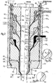
- the known extrusion head illustrated in FIG. 1 as well as that according to the invention shown in FIG. 2, are intended for the extrusion of a three-layer parison, but it is obvious that the description which follows will apply as well to the cases of the simple extrusion of a single-layer parison as of the coextrusion parison to more than one layer.
- the known coextrusion head comprises from top to bottom in the upper stage 10, a medium stage 12, a lower stage 14 and a die 16.
- Each of these stages comprises an annular flange 18 in T, and two flat annular flanges 20 and 22 stacked on top of each other.
- the flanges of the upper stage will be assigned index 1, those of the middle stage of index 2 and those of the lower stage of index 3.
- Under the flange 18 3 is fixed an annular flange of base 18 4 .
- All these flanges as well as the die 16 respectively have bores centered on the same axis xx and traversed with clearance by a fixed torpedo 26 comprising a punch holder 28 and a punch 30 and which defines with said bore an tubulaire.24 channel 2 24 4 whose thickness increases when moving from one T-flange to the next.
- the flanges 18 of each stage have on their central base a frustoconical wall 32 inclined towards the axis x-x and towards the die, and on the upper edge of their bore a frustoconical chamfer 34 of the same conicity as the wall 32.
- the flat flange 20 of each stage is disposed under the associated flange 18 and has an internal diameter much smaller than that of the latter. Its bore is limited by a frustoconical flank 36 located in the extension of the chamfer 34 of the flange 18 of the immediately lower stage.
- the frustoconical walls 34 and 36 are located opposite the frustoconical wall 32 of the flange 18.
- the flat flange 22 of each stage is interposed between the flange 20 of the same stage and the flange 18 of the immediately lower stage and its internal diameter is even smaller than that of the flange 20, so that a space is formed annular 38 limited above by the lower horizontal surface 40 of the flange 20, below by the upper horizontal surface 42 of the flange 18 of the neighboring stage, and internally by the frustoconical wall 32 of the flange of the same stage.
- an adjustment ring 44 provided with a frustoconical bore 46 dimensioned so that, when the ring is centered on the axis xx, the wall of said bore comes exactly complete the frustoconical walls 34 and 36 from flanges 20 and 18 which frame the centering ring 44, thereby forming a continuous frustoconical surface located opposite the frustoconical wall 32 of the flange 18 of the same floor.
- This surface forms, with the wall 32 located opposite, a narrow tubular passage 48 of frustoconical shape which communicates with the central channel 24.
- Each of the flanges 20 has a passage 50 leading to an annular chamber 52 connected to the tubular passage 48. To the passage 50 is connected a conduit 54 for supplying the material to be extruded.
- a tube of material is formed with one layer and a new layer is added to each of the following stages, so that at the outlet of the die 16 a three-layer parison 55 is obtained .
- the upper stage 10 is supplied from the left, the middle stage by. the right and the lower floor by the left.
- the material tends to be distributed in a non-uniform manner around the tubular passages 48.
- the adjustment rings 44 can be moved horizontally in a direction which promotes uniform distribution.
- the ring 44 1 has been offset to the left and the rings 44 2 and 44 3 to the right.
- Adjustment screws 56 are used for this purpose which bear at the end on the outer face of the rings 44.
- the die 16 can be moved in the same way by means of screws.
- This adjustment assembly can be constituted for example by three screws arranged at 120 ° from one another on the circumference of the same circle, or by two screws and a spring return device.
- the screws can be operated manually or by cylinders. They can also be replaced by cylinders.
- These jacks are just one example of a means of remote control devices, which can be controlled from a device for detecting the geometric quality of the preform.
- the actuator rods 86, 87 pass through the flanges 64t, 64 2 , 64 3 and 64 4 or pass outside and bear at their end on the horizontal face 85 of the die 66 or its geometric extension.
- cylinder rods 88, 89 they pass through the flanges 64 1 , 64 2 and 64 3 and vertical bores 90 1 and 90 2 drilled respectively through the rings 74 1 and 74 2 and come to bear at their ends on the upper face 82 of the ring 74 3 .
- the mode of adjustment of the coextrusion head according to the invention is as follows:
- each annular passage 84 has a constant thickness over its entire periphery. If there is an irregularity on one of the layers of the parison 55 leaving the die 66, this defect is eliminated by acting in a defined direction on the screws or jacks associated with the ring which forms said layer. For example, if the outermost layer of the parison 55 is thicker along a generatrix located on the right in FIG. 2, the actuator rod 88 must be pushed in after having retracted the two other actuator rods 89.
- the ring 74 3 then tilts around point 0 3 , clockwise, l the ring being guided in this movement by the contiguous carrying surfaces formed on the adjacent flanges 64, and therefore a narrowing of the channel 84 3 on the right side in the figure at the same time as an enlargement of the same channel on its left side.
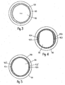
- the torpedo and flange bore sections are always circular. By. on the other hand, this is not necessarily the case for the end 96 of the punch 30 and for the outlet edge 98 of the die 66.
- Fig. 3 shows the case where said end 96 and said edge 98 are circular.
- complementary machining is carried out on one or more generators 100, 102 (100 ′, 102 ′) from the end of the punch or from the edge of tapering 98 of the die so as to obtain areas for reinforcing material 104 , 106 on one or more generators of the preform.
- This device is applicable to the head according to the invention, as. it is to all classic heads. It allows the wall of the preform to be reinforced in areas where the article to be molded must have a greater thickness. This is the case for example for hollow bodies of square or rectangular section, where the edges must be particularly reinforced to resist shocks and stresses.
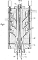
- Fig. 6 shows an alternative embodiment of the head of FIG. 2, in which the ring adjustment system is combined with a preformed thickness variation device known per se.
- This device consists of a rod 110 which crosses from top to bottom an axial bore 112 drilled in the torpedo 26.
- the lower end of the rod 110 is secured, for example by screwing, with a punch 114 which is slidably mounted in a bore 116 following the bore 112.
- the rod 110 gives the punch 114 an alternating movement, programmed by means of a hydraulic, pneumatic, mechanical, electrical or other control system capable of acting on the upper end of the rod .
- the "air gap" between the frustoconical wall 118 of the punch 114 and the outlet edge 98 of the die varies in thickness.
- a preform 55 programmed in thickness is thus obtained, presenting variations in thickness which make it possible to optimize the quantity of material as a function of the requirements on the finished object.
Landscapes
- Engineering & Computer Science (AREA)
- Mechanical Engineering (AREA)
- Manufacturing & Machinery (AREA)
- Extrusion Moulding Of Plastics Or The Like (AREA)
- Blow-Moulding Or Thermoforming Of Plastics Or The Like (AREA)
- Processing And Handling Of Plastics And Other Materials For Molding In General (AREA)
- Nozzles (AREA)
Applications Claiming Priority (2)
| Application Number | Priority Date | Filing Date | Title |
|---|---|---|---|
| FR8107125A FR2503627A1 (fr) | 1981-04-09 | 1981-04-09 | Tete pour l'extrusion d'une paraison tubulaire a au moins une couche de matiere |
| FR8107125 | 1981-04-09 |
Publications (2)
| Publication Number | Publication Date |
|---|---|
| EP0063060A1 EP0063060A1 (fr) | 1982-10-20 |
| EP0063060B1 true EP0063060B1 (fr) | 1984-07-18 |
Family
ID=9257199
Family Applications (1)
| Application Number | Title | Priority Date | Filing Date |
|---|---|---|---|
| EP82400443A Expired EP0063060B1 (fr) | 1981-04-09 | 1982-03-12 | Tête pour l'extrusion d'une paraison tubulaire à au moins une couche de matière |
Country Status (7)
| Country | Link |
|---|---|
| US (1) | US4472129A (enExample) |
| EP (1) | EP0063060B1 (enExample) |
| JP (1) | JPS57178727A (enExample) |
| AR (1) | AR226635A1 (enExample) |
| DE (2) | DE63060T1 (enExample) |
| ES (1) | ES8304478A1 (enExample) |
| FR (1) | FR2503627A1 (enExample) |
Families Citing this family (75)
| Publication number | Priority date | Publication date | Assignee | Title |
|---|---|---|---|---|
| DE3216377A1 (de) * | 1981-09-26 | 1983-06-16 | Detlef Dipl.-Ing. 4970 Bad Oeynhausen Gneuss | Vorrichtung zur herstellung von rohren aus plastischen massen |
| US4465449A (en) * | 1982-12-06 | 1984-08-14 | Borg-Warner Chemicals, Inc. | Coextrusion feedblock for making lightweight, rigid thermoplastic pipe |
| US4751651A (en) * | 1983-08-16 | 1988-06-14 | Phillips Petroleum Company | Shaping of dies |
| FR2557016A2 (fr) * | 1983-12-23 | 1985-06-28 | Raffinage Cie Francaise | Tete pour l'extrusion d'une paraison tubulaire a au moins une couche de matiere polymere |
| DE3405257C2 (de) * | 1984-02-15 | 1986-05-22 | Reifenhäuser GmbH & Co Maschinenfabrik, 5210 Troisdorf | Vorrichtung zum kontinuierlichen Strangpressen einer mehrschichtigen Kunststoffbahn |
| US4657497A (en) * | 1984-03-20 | 1987-04-14 | Solvay & Cie (Societe Anonyme) | Device for the coextrusion of thermoplastics |
| US4578025A (en) * | 1984-11-21 | 1986-03-25 | Kazuo Ando | Die assembly for extruding multilayer parisons |
| IT1177349B (it) * | 1984-11-28 | 1987-08-26 | Prandi G & C Off Mec | Testa di coestrusione circolare di piu' strati di materiali termoplastici |
| US4574067A (en) * | 1985-03-01 | 1986-03-04 | Ball Corporation | Crosshead with static mixers |
| DE3510181A1 (de) * | 1985-03-21 | 1986-10-02 | Hoechst CeramTec AG, 8672 Selb | Extrudiervorrichtung zum herstellen von wabenkoerpern |
| US4677006A (en) * | 1985-05-29 | 1987-06-30 | E. I. Du Pont De Nemours And Company | Seamless laminar article |
| US4731216A (en) * | 1985-05-29 | 1988-03-15 | E. I. Du Pont De Nemours And Company | Process for manufacturing a seamless laminar article |
| JPS6299115A (ja) * | 1985-10-25 | 1987-05-08 | Mazda Motor Corp | 多層パリソンの押出成形装置 |
| DE3601345A1 (de) * | 1986-01-18 | 1987-07-23 | Reifenhaeuser Masch | Strangpresswerkzeug fuer die herstellung einer mehrschichtigen schlauchfolie |
| US4711623A (en) * | 1986-05-13 | 1987-12-08 | Mobil Oil Corporation | Annular extrusion die with internal choke ring and spider mandrel |
| US4798526A (en) * | 1986-07-17 | 1989-01-17 | General Electric Company | Modular extrusion head |
| US4895744A (en) * | 1986-06-26 | 1990-01-23 | General Electric Company | Method of making a multi-layer parison |
| JPH0649317B2 (ja) * | 1986-06-26 | 1994-06-29 | ゼネラル・エレクトリック・カンパニイ | モジュラー押出ヘッド |
| DE3635334C3 (de) * | 1986-10-17 | 1997-04-03 | Guenter Richter | Vorrichtung zur diskontinuierlichen Herstellung mehrschichtiger, coextrudierter, schlauchartiger Vorformlinge aus thermoplastischem Kunststoff für das Blasformen |
| US5186875A (en) * | 1987-04-17 | 1993-02-16 | Mazda Motor Corporation | Method of manufacturing of a novel hollow multi-layer article |
| JP2584658B2 (ja) * | 1988-04-28 | 1997-02-26 | マツダ株式会社 | 多層ブロー装置 |
| FR2635482B1 (fr) * | 1988-08-16 | 1991-02-01 | Solvay | Procede et filiere pour l'extrusion de tuyaux en matiere thermoplastique |
| US4940403A (en) * | 1989-05-01 | 1990-07-10 | Hoover Universal, Inc. | Dual parison extrusion head for multi-layer blow molding |
| DE69002295T2 (de) | 1989-09-25 | 1993-11-04 | Schneider Usa Inc | Mehrschichtextrusion als verfahren zur herstellung von ballons zur gefaessplastik. |
| US5204120A (en) * | 1989-10-31 | 1993-04-20 | Hoover Universal, Inc. | Intermittent multi-layer multi-parison extrusion head |
| JPH0366722U (enExample) * | 1989-10-31 | 1991-06-28 | ||
| US5102602A (en) * | 1990-06-04 | 1992-04-07 | Plastics Usa Corporation | Adjustable diehead |
| CA2039500C (en) * | 1990-07-18 | 1994-02-15 | Takahisa Kawaguchi | Apparatus for forming bent portion of pipe in apparatus for making bent pipe |
| US5069850A (en) * | 1990-07-24 | 1991-12-03 | Bridgestone/Firestone, Inc. | Coextrusion apparatus and method using a rigid die for varying the outer profile of a tubular extrudate |
| US5128084A (en) * | 1990-07-24 | 1992-07-07 | Bridgestone Firestone Inc | Coextrusion apparatus and method for varying the inner profile of a tubular extrudate |
| US5062782A (en) * | 1990-07-24 | 1991-11-05 | Bridgestone/Firestone, Inc. | Coextrusion apparatus for varying the inner and/or outer profile of a tubular extrudate |
| US5108682A (en) * | 1990-07-24 | 1992-04-28 | Bridgestone/Firestone, Inc. | Coextrusion apparatus and method using an elastic die for varying the outer profile of a tubular extrudate |
| DE4111228A1 (de) * | 1991-04-08 | 1992-10-15 | Wilhelm Hegler | Vorrichtung zur herstellung von kunststoff-rohren |
| US5195969A (en) | 1991-04-26 | 1993-03-23 | Boston Scientific Corporation | Co-extruded medical balloons and catheter using such balloons |
| CA2082437C (en) * | 1991-11-14 | 1998-01-20 | Peter C. Gates | Spiral fed multi-layer tubular die |
| JP2545325Y2 (ja) * | 1992-01-22 | 1997-08-25 | 石川島播磨重工業株式会社 | ブロー成形機のパリソンヘッド |
| JP2761695B2 (ja) * | 1993-01-20 | 1998-06-04 | 住友ゴム工業株式会社 | プリフォーマー |
| US5358570A (en) * | 1993-07-22 | 1994-10-25 | Drawbaugh William W | Crosshead apparatus for jacketing wire core |
| US6896842B1 (en) | 1993-10-01 | 2005-05-24 | Boston Scientific Corporation | Medical device balloons containing thermoplastic elastomers |
| EP0738168B1 (en) | 1993-10-01 | 2004-01-21 | Boston Scientific Corporation | Medical device balloons containing thermoplastic elastomers |
| US5674440A (en) * | 1995-05-05 | 1997-10-07 | Graham Engineering Corporation | Die head with adjustable mandrel and method |
| JP2986397B2 (ja) * | 1995-12-28 | 1999-12-06 | タイガースポリマー株式会社 | 押出し成形装置およびパリソンの成形方法 |
| US5851566A (en) * | 1996-07-02 | 1998-12-22 | Avery Dennison | Applicator die |
| JPH10231961A (ja) | 1997-02-18 | 1998-09-02 | Tigers Polymer Corp | 合成樹脂ブロー成形ホース |
| DE19843341A1 (de) * | 1998-09-22 | 2000-04-06 | Strumann Werner Egeplast | Vorrichtung zur Herstellung von Kunststoffrohren |
| US6382944B1 (en) * | 1998-11-10 | 2002-05-07 | Guill Tool & Engineering Co., Inc. | Universally mounted adjustable die |
| US6902388B2 (en) * | 1998-11-10 | 2005-06-07 | Guill Tool And Engineering Co., Inc. | Pivotally adjustable die |
| FR2791643B1 (fr) | 1999-03-30 | 2001-09-14 | Vg Emballage | Poche de distribution par pompe doseuse d'un produit conserve a l'abri de l'air, et ensemble de conditionnement et de distribution la contenant |
| JP4089113B2 (ja) * | 1999-12-28 | 2008-05-28 | 株式会社Ihi | 薄膜作成装置 |
| US7947059B2 (en) | 2000-03-02 | 2011-05-24 | Boston Scientific Scimed, Inc. | Multilayer medical device |
| FI108412B (fi) * | 2000-03-28 | 2002-01-31 | Nextrom Holding Sa | Sovitelma puristinty÷kalujen yhteydessõ |
| US6769899B2 (en) * | 2001-02-09 | 2004-08-03 | American Maplan Corporation | Independent X/Y flow adjustable extrusion die |
| DE10237051A1 (de) * | 2002-08-09 | 2004-02-26 | Sig Technology Ltd. | Verfahren und Vorrichtung zur Herstellung blasgeformter Hohlkörper aus thermoplastischen Kunststoffen |
| US7488339B2 (en) * | 2002-10-21 | 2009-02-10 | Boston Scientific Scimed, Inc. | Multilayer medical device |
| US6951675B2 (en) * | 2003-01-27 | 2005-10-04 | Scimed Life Systems, Inc. | Multilayer balloon catheter |
| US20040164464A1 (en) * | 2003-02-21 | 2004-08-26 | Lubberts Robert B. | Device and method of correcting extrudate bow |
| US6915647B2 (en) * | 2003-05-21 | 2005-07-12 | Hoshizaki Denki Kabushiki Kaisha | Abnormality detecting device of auger-type ice making machine and abnormality detecting method thereof |
| US7329113B2 (en) * | 2004-03-19 | 2008-02-12 | Leseman Steven R | Adjustable extrusion die |
| DE102004015551A1 (de) * | 2004-03-30 | 2005-10-20 | Guenter Richter | Vorrichtung zur Herstellung schlauchartiger Vorformlinge mit asymmetrischem Ringkolben |
| DE102004028100B4 (de) * | 2004-06-09 | 2009-09-17 | Thermo-Technik-Systeme Gmbh | Extrusionsblaskopf |
| DE202004011742U1 (de) * | 2004-07-27 | 2004-10-14 | REIFENHäUSER GMBH & CO. MASCHINENFABRIK | Koextrusionsadapter |
| WO2006060345A2 (en) * | 2004-11-30 | 2006-06-08 | Blackett Peter W | Extrusion die for the production of polymeric blown films |
| CA2622692C (en) * | 2007-02-26 | 2015-10-06 | Advanced Drainage Systems, Inc. | Defined ratio dual-wall pipe die |
| DE102007050694B4 (de) * | 2007-10-22 | 2012-05-10 | Ulrich Büttel | Blaskopf für eine Blasfolienextrusionsanlage |
| US8876512B2 (en) * | 2008-09-23 | 2014-11-04 | Cryovac, Inc. | Die for coextruding a plurality of fluid layers |
| US20100072655A1 (en) * | 2008-09-23 | 2010-03-25 | Cryovac, Inc. | Die, system, and method for coextruding a plurality of fluid layers |
| EP2398329A2 (en) * | 2009-01-23 | 2011-12-28 | Mars, Incorporated | Product shaping method and apparatus |
| JP5693258B2 (ja) * | 2011-01-26 | 2015-04-01 | 日本コヴィディエン株式会社 | 押出成形金型、押出成形装置、及び、医療用チューブの製造方法 |
| DE102012022409B3 (de) * | 2012-11-15 | 2013-05-29 | Heinz Gross | Schlauchkopf mit trifunktionellem Bauteil |
| US20180187802A1 (en) * | 2016-12-30 | 2018-07-05 | Polyflow Llc | Multi-layer pipes |
| CN107310127B (zh) * | 2017-08-08 | 2023-05-05 | 中国化学工业桂林工程有限公司 | 一种快开式橡胶挤出机头 |
| CN112936528B (zh) * | 2021-01-22 | 2022-11-11 | 株洲市创锐高强陶瓷有限公司 | 一种防挤出口挤出破裂的陶瓷成型设备 |
| JP7538744B2 (ja) * | 2021-03-03 | 2024-08-22 | 株式会社日本製鋼所 | 押出装置およびそれに用いられる押出成形用ダイ、監視装置およびプログラム、ストランドの製造方法、ならびに、ストランド径の調整方法 |
| CN113580531A (zh) * | 2021-08-06 | 2021-11-02 | 中科纳通(山东)新材料有限公司 | 一种三层结构式胶条及其挤出用模具 |
| CN113715294B (zh) * | 2021-08-09 | 2023-08-01 | 青岛橡六胶管有限公司 | 胶管挤出一体机 |
Family Cites Families (17)
| Publication number | Priority date | Publication date | Assignee | Title |
|---|---|---|---|---|
| US2349178A (en) * | 1941-08-04 | 1944-05-16 | Plax Corp | Method of and apparatus for extruding and blowing organic plastic materials |
| US2824337A (en) * | 1955-07-28 | 1958-02-25 | Du Pont | Circular extrusion die |
| US3078507A (en) * | 1958-11-19 | 1963-02-26 | Brockway Glass Co Inc | Method and apparatus for making plastic articles |
| US3111714A (en) * | 1962-05-14 | 1963-11-26 | Phillips Petroleum Co | Self-centering extrusion die |
| US3184792A (en) * | 1962-12-31 | 1965-05-25 | Nat Distillers Chem Corp | Variable orifice extrusion die |
| SE301378B (enExample) * | 1963-08-27 | 1968-06-04 | Kalle Ag | |
| US3309443A (en) * | 1963-12-13 | 1967-03-14 | Phillips Petroleum Co | Plastic molding |
| US3332112A (en) * | 1965-07-06 | 1967-07-25 | Brockway Glass Co Inc | Apparatus for extruding hollow plastic articles |
| US3382539A (en) * | 1966-08-04 | 1968-05-14 | Continental Can Co | Extrusion die shell adjustment |
| US3453690A (en) * | 1967-05-26 | 1969-07-08 | Midland Ross Corp | Variable area extruder die-head |
| US3753636A (en) * | 1971-03-12 | 1973-08-21 | Graham Eng Corp | Phase variator for blow molding equipment |
| JPS5137938B2 (enExample) * | 1971-12-29 | 1976-10-19 | ||
| US3899276A (en) * | 1973-05-29 | 1975-08-12 | Beloit Corp | Annular extrusion die with back pressure control |
| JPS51147556A (en) * | 1975-06-13 | 1976-12-17 | Toyo Soda Mfg Co Ltd | Multiilayer rotary circular die |
| JPS6058011B2 (ja) * | 1975-08-12 | 1985-12-18 | 凸版印刷株式会社 | ブロ−成形用多層パリソン成形装置 |
| US4047868A (en) * | 1975-08-12 | 1977-09-13 | Toppan Printing Co., Ltd. | Multilayer parison extrusion molding machine for blow molding |
| US4171195A (en) * | 1977-11-17 | 1979-10-16 | Scientific Process & Research, Inc. | Cross-head die with volumetric flow compensation means |
-
1981
- 1981-04-09 FR FR8107125A patent/FR2503627A1/fr active Granted
-
1982
- 1982-03-12 EP EP82400443A patent/EP0063060B1/fr not_active Expired
- 1982-03-12 DE DE198282400443T patent/DE63060T1/de active Pending
- 1982-03-12 DE DE8282400443T patent/DE3260391D1/de not_active Expired
- 1982-03-26 AR AR288884A patent/AR226635A1/es active
- 1982-04-01 JP JP57052365A patent/JPS57178727A/ja active Pending
- 1982-04-05 US US06/365,258 patent/US4472129A/en not_active Expired - Fee Related
- 1982-04-07 ES ES511266A patent/ES8304478A1/es not_active Expired
Also Published As
| Publication number | Publication date |
|---|---|
| JPS57178727A (en) | 1982-11-04 |
| FR2503627A1 (fr) | 1982-10-15 |
| ES511266A0 (es) | 1983-03-01 |
| EP0063060A1 (fr) | 1982-10-20 |
| FR2503627B1 (enExample) | 1984-05-18 |
| DE63060T1 (de) | 1983-04-28 |
| AR226635A1 (es) | 1982-07-30 |
| US4472129A (en) | 1984-09-18 |
| ES8304478A1 (es) | 1983-03-01 |
| DE3260391D1 (en) | 1984-08-23 |
Similar Documents
| Publication | Publication Date | Title |
|---|---|---|
| EP0063060B1 (fr) | Tête pour l'extrusion d'une paraison tubulaire à au moins une couche de matière | |
| CA2293843C (fr) | Tuyere de soufflage de recipients en matiere plastique et installation pourvue d'une telle tuyere | |
| FR3070678B1 (fr) | Procede et dispositif de reglage d'un convoyeur de preformes | |
| EP2129505B1 (fr) | Methode de realisation d'un objet multicouche et objet ainsi obtenu | |
| WO2001068491A1 (fr) | Tronçon courbe de convoyeur avec rails de guidage a ecartement reglable | |
| EP1268158A1 (fr) | Procede et ligne de fabrication en continu de tubes en matiere plastique avec etirage bi-axial, et tube en matiere plastique obtenu | |
| EP1701147A1 (fr) | Installation de fabrication de tuyaux et procédé de détection de défauts associé | |
| EP1603731A2 (fr) | Procede de fabrication en continu de tubes en matiere plastique avec etirage bi-axial et ligne de fabrication pour ce procede. | |
| EP1343624B1 (fr) | Dispositif d'extrusion pour fabriquer un produit a base d'un melange caoutchouteux | |
| FR2475976A1 (fr) | Tete d'extrusion et son procede de fabrication | |
| EP0239136B1 (fr) | Dispositif pour mouler par injection des préformes tubulaires en matière thermoplastique | |
| FR3066137A1 (fr) | Procede de determination d'une position geometrique d'un corps creux et dispositif de traitement pour positionner un corps creux dans une position de reference | |
| EP0494566B1 (fr) | Appareillage d'extrusion pour l'obtention d'un profilé à structure alvéolaire en résine thermoplastique. | |
| WO2006003310A1 (fr) | Installation de soufflage ou d’etirage-soufflage a tuyere-cloche pour la fabrication de recipients en materiau thermoplastique et moule pour une telle installation | |
| JP2009255393A (ja) | 筒状プラスチックの押出成形機 | |
| EP0246142A1 (fr) | Machine d'extrusion simultanée de plusieurs matières | |
| FR2691647A1 (fr) | Procédé et dispositif de formage d'objets en verre creux, objets obtenus. | |
| FR2479037A1 (fr) | Laminoir oblique pour la fabrication de tubes sans soudure | |
| FR2659481A1 (fr) | Procede et installation de formage d'une levre circulaire autour d'une ouverture. | |
| EP3727794B1 (fr) | Fond de moule monobloc a circulation fluidique optimisée | |
| EP1023158A1 (fr) | Galet de pressage pour presse a granuler et presse a granuler equipee de tels galets | |
| EP1100672B1 (fr) | Dispositif de regulation de l'epaisseur d'une paraison dans une machine d'extrusion-soufflage | |
| EP0366773B1 (fr) | Procede et appareil pour enduire de caoutchouc des fils deroules en parallele et produire ainsi une nappe | |
| EP1963075B1 (fr) | Dispositif de commande par organe suiveur et chemin de came d'un element de machine de traitement de recipients et machine de traitement de recipients comprenant un tel dispositif | |
| EP3389971B1 (fr) | Preforme pourvue d'une portion de corps concave |
Legal Events
| Date | Code | Title | Description |
|---|---|---|---|
| PUAI | Public reference made under article 153(3) epc to a published international application that has entered the european phase |
Free format text: ORIGINAL CODE: 0009012 |
|
| AK | Designated contracting states |
Designated state(s): BE DE GB IT NL |
|
| ITCL | It: translation for ep claims filed |
Representative=s name: BARZANO' E ZANARDO MILANO S.P.A. |
|
| TCNL | Nl: translation of patent claims filed | ||
| 17P | Request for examination filed |
Effective date: 19821129 |
|
| DET | De: translation of patent claims | ||
| ITF | It: translation for a ep patent filed | ||
| GRAA | (expected) grant |
Free format text: ORIGINAL CODE: 0009210 |
|
| AK | Designated contracting states |
Designated state(s): BE DE GB IT NL |
|
| REF | Corresponds to: |
Ref document number: 3260391 Country of ref document: DE Date of ref document: 19840823 |
|
| PLBE | No opposition filed within time limit |
Free format text: ORIGINAL CODE: 0009261 |
|
| STAA | Information on the status of an ep patent application or granted ep patent |
Free format text: STATUS: NO OPPOSITION FILED WITHIN TIME LIMIT |
|
| 26N | No opposition filed | ||
| PG25 | Lapsed in a contracting state [announced via postgrant information from national office to epo] |
Ref country code: NL Effective date: 19851001 |
|
| NLV4 | Nl: lapsed or anulled due to non-payment of the annual fee | ||
| PG25 | Lapsed in a contracting state [announced via postgrant information from national office to epo] |
Ref country code: DE Effective date: 19861202 |
|
| BERE | Be: lapsed |
Owner name: CIE FRANCAISE DE RAFFINAGE Effective date: 19870331 |
|
| GBPC | Gb: european patent ceased through non-payment of renewal fee | ||
| PG25 | Lapsed in a contracting state [announced via postgrant information from national office to epo] |
Ref country code: GB Effective date: 19881121 |
|
| PG25 | Lapsed in a contracting state [announced via postgrant information from national office to epo] |
Ref country code: BE Effective date: 19890331 |