EP0062582A1 - Profilé de châssis, notamment de capteur solaire, incorporable en toiture - Google Patents
Profilé de châssis, notamment de capteur solaire, incorporable en toiture Download PDFInfo
- Publication number
- EP0062582A1 EP0062582A1 EP82400601A EP82400601A EP0062582A1 EP 0062582 A1 EP0062582 A1 EP 0062582A1 EP 82400601 A EP82400601 A EP 82400601A EP 82400601 A EP82400601 A EP 82400601A EP 0062582 A1 EP0062582 A1 EP 0062582A1
- Authority
- EP
- European Patent Office
- Prior art keywords
- profile according
- profile
- chassis
- glazing
- branch
- Prior art date
- Legal status (The legal status is an assumption and is not a legal conclusion. Google has not performed a legal analysis and makes no representation as to the accuracy of the status listed.)
- Withdrawn
Links
- 239000011324 bead Substances 0.000 claims description 21
- XLYOFNOQVPJJNP-UHFFFAOYSA-N water Substances O XLYOFNOQVPJJNP-UHFFFAOYSA-N 0.000 claims description 5
- 238000007789 sealing Methods 0.000 description 8
- 238000009434 installation Methods 0.000 description 6
- 239000011521 glass Substances 0.000 description 3
- 238000010348 incorporation Methods 0.000 description 3
- 235000014676 Phragmites communis Nutrition 0.000 description 2
- 238000005192 partition Methods 0.000 description 2
- 229910000746 Structural steel Inorganic materials 0.000 description 1
- 238000010521 absorption reaction Methods 0.000 description 1
- 238000010276 construction Methods 0.000 description 1
- 230000008030 elimination Effects 0.000 description 1
- 238000003379 elimination reaction Methods 0.000 description 1
- 229940082150 encore Drugs 0.000 description 1
- 239000006260 foam Substances 0.000 description 1
- 230000000149 penetrating effect Effects 0.000 description 1
- 230000000630 rising effect Effects 0.000 description 1
- 238000010079 rubber tapping Methods 0.000 description 1
- 239000010865 sewage Substances 0.000 description 1
- 239000010454 slate Substances 0.000 description 1
Images


Classifications
-
- F—MECHANICAL ENGINEERING; LIGHTING; HEATING; WEAPONS; BLASTING
- F24—HEATING; RANGES; VENTILATING
- F24S—SOLAR HEAT COLLECTORS; SOLAR HEAT SYSTEMS
- F24S80/00—Details, accessories or component parts of solar heat collectors not provided for in groups F24S10/00-F24S70/00
- F24S80/40—Casings
- F24S80/45—Casings characterised by the material
- F24S80/453—Casings characterised by the material made of metallic material
-
- F—MECHANICAL ENGINEERING; LIGHTING; HEATING; WEAPONS; BLASTING
- F24—HEATING; RANGES; VENTILATING
- F24S—SOLAR HEAT COLLECTORS; SOLAR HEAT SYSTEMS
- F24S20/00—Solar heat collectors specially adapted for particular uses or environments
- F24S20/60—Solar heat collectors integrated in fixed constructions, e.g. in buildings
- F24S20/67—Solar heat collectors integrated in fixed constructions, e.g. in buildings in the form of roof constructions
-
- F—MECHANICAL ENGINEERING; LIGHTING; HEATING; WEAPONS; BLASTING
- F24—HEATING; RANGES; VENTILATING
- F24S—SOLAR HEAT COLLECTORS; SOLAR HEAT SYSTEMS
- F24S25/00—Arrangement of stationary mountings or supports for solar heat collector modules
- F24S25/20—Peripheral frames for modules
-
- F—MECHANICAL ENGINEERING; LIGHTING; HEATING; WEAPONS; BLASTING
- F24—HEATING; RANGES; VENTILATING
- F24S—SOLAR HEAT COLLECTORS; SOLAR HEAT SYSTEMS
- F24S80/00—Details, accessories or component parts of solar heat collectors not provided for in groups F24S10/00-F24S70/00
- F24S80/70—Sealing means
-
- F—MECHANICAL ENGINEERING; LIGHTING; HEATING; WEAPONS; BLASTING
- F24—HEATING; RANGES; VENTILATING
- F24S—SOLAR HEAT COLLECTORS; SOLAR HEAT SYSTEMS
- F24S25/00—Arrangement of stationary mountings or supports for solar heat collector modules
- F24S2025/01—Special support components; Methods of use
- F24S2025/021—Sealing means between support elements and mounting surface
-
- F—MECHANICAL ENGINEERING; LIGHTING; HEATING; WEAPONS; BLASTING
- F24—HEATING; RANGES; VENTILATING
- F24S—SOLAR HEAT COLLECTORS; SOLAR HEAT SYSTEMS
- F24S25/00—Arrangement of stationary mountings or supports for solar heat collector modules
- F24S25/60—Fixation means, e.g. fasteners, specially adapted for supporting solar heat collector modules
- F24S2025/6004—Fixation means, e.g. fasteners, specially adapted for supporting solar heat collector modules by clipping, e.g. by using snap connectors
-
- Y—GENERAL TAGGING OF NEW TECHNOLOGICAL DEVELOPMENTS; GENERAL TAGGING OF CROSS-SECTIONAL TECHNOLOGIES SPANNING OVER SEVERAL SECTIONS OF THE IPC; TECHNICAL SUBJECTS COVERED BY FORMER USPC CROSS-REFERENCE ART COLLECTIONS [XRACs] AND DIGESTS
- Y02—TECHNOLOGIES OR APPLICATIONS FOR MITIGATION OR ADAPTATION AGAINST CLIMATE CHANGE
- Y02A—TECHNOLOGIES FOR ADAPTATION TO CLIMATE CHANGE
- Y02A30/00—Adapting or protecting infrastructure or their operation
- Y02A30/60—Planning or developing urban green infrastructure
-
- Y—GENERAL TAGGING OF NEW TECHNOLOGICAL DEVELOPMENTS; GENERAL TAGGING OF CROSS-SECTIONAL TECHNOLOGIES SPANNING OVER SEVERAL SECTIONS OF THE IPC; TECHNICAL SUBJECTS COVERED BY FORMER USPC CROSS-REFERENCE ART COLLECTIONS [XRACs] AND DIGESTS
- Y02—TECHNOLOGIES OR APPLICATIONS FOR MITIGATION OR ADAPTATION AGAINST CLIMATE CHANGE
- Y02B—CLIMATE CHANGE MITIGATION TECHNOLOGIES RELATED TO BUILDINGS, e.g. HOUSING, HOUSE APPLIANCES OR RELATED END-USER APPLICATIONS
- Y02B10/00—Integration of renewable energy sources in buildings
- Y02B10/20—Solar thermal
-
- Y—GENERAL TAGGING OF NEW TECHNOLOGICAL DEVELOPMENTS; GENERAL TAGGING OF CROSS-SECTIONAL TECHNOLOGIES SPANNING OVER SEVERAL SECTIONS OF THE IPC; TECHNICAL SUBJECTS COVERED BY FORMER USPC CROSS-REFERENCE ART COLLECTIONS [XRACs] AND DIGESTS
- Y02—TECHNOLOGIES OR APPLICATIONS FOR MITIGATION OR ADAPTATION AGAINST CLIMATE CHANGE
- Y02E—REDUCTION OF GREENHOUSE GAS [GHG] EMISSIONS, RELATED TO ENERGY GENERATION, TRANSMISSION OR DISTRIBUTION
- Y02E10/00—Energy generation through renewable energy sources
- Y02E10/40—Solar thermal energy, e.g. solar towers
- Y02E10/47—Mountings or tracking
Definitions
- the present invention relates to a solar collector frame or a similar device, the frame being intended to be incorporated in a roof, in particular in a tiled or slate roof. It also relates to sealing parts and their assembly devices on the chassis.
- a very simple frame for which all the sealing parts, that is to say the upper flap, the sewage flap, the side noquets and a frame acting as flashing, must be shaped piecemeal by the roofer.
- a chassis is also known for which these factory-shaped parts must be screwed on site and which requires the installation, in order to perfect the seal, of attached synthetic foam gasket.
- the glazing fixing frame In another frame, the glazing fixing frame must be dismantled for the installation of noquets and flaps, then reassemble, which reduces the reliability of the sensor's tightness.
- An object of the present invention is to provide a rectangular chassis profile which allows the use of such commercial sealing parts, that is to say upper flap, sewer, side noquets.
- Another object of the invention is to provide sealing pieces of the flashing type fixed to the chassis and which, in combination with the commercial pieces, seal the chassis with the roof, said flashing type pieces being mounted. using simple means of clipping, without screwing, or adding additional seals on site.
- a chassis profile which has the general shape of an L whose leg is surmounted by a first horizontal U open towards the outside of the chassis, the lower branch of said first U having its middle part secured to the top of the leg of the L while the upper branch of said first U constitutes the bottom of a second vertical U open upwards.
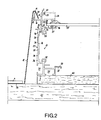
- Fig. 1 shows a solar collector 1, the chassis of which is formed by four vertical walls: a high horizontal wall defined by its upper edge 2 and its lower edge 3, a lower horizontal wall defined its upper horizontal edge 4 and its lower edge 5, and two oblique walls respectively defined each by its upper edge 6 and its lower edge 7.
- the walls of the frame are assumed to be without thickness only for clarity of the drawing.
- the walls 6-7 each carry a flashing or reed 8 under which are posed noquets 9
- the wall 4-5 carries a flashing or reed 10 under which is installed an enveloping flap or return of water 11, and the wall 2-3 is chaperoned by an enveloping flap or hood 12.
- parts 9, 11 and 12 listed above are parts which are commonly marketed for the incorporation of certain snuff windows in the roof.
- the walls of the chassis are formed by a single profile 13 which has the shape of an L whose leg 14 is surmounted by a first horizontal U open towards the outside of the chassis, the lower horizontal branch 15 of the first U having its middle part secured to the top of the branch 14 while the upper branch 16 constitutes the bottom of a second vertical U open upwards.
- the outer branch 17 of the second U ends in a bead 18 while its inner branch 19 ends in a horizontal flange 20 facing the inside of the chassis.
- the flanges 20 and 22 have the same length and end in short hooks 23 and 24 directed towards each other.
- a horizontal slot 25 is provided, consisting of an extension of the branch 15 and a dropout from the bottom 26 of the base 21. Opposite the bottom from the slot 25, there is provided a wide rim 27 facing the inside of the chassis. At the junction between the branch 15 and the rim 27, a circular groove 28 open downwards is provided.
- the base of the L is formed by the walls of a T-groove 30 open towards the bottom and a T-groove 31 open towards the outside of the frame.
- a side wall of the groove 30 is extended upward to form the bottom of the groove 31.
- the leg 13 of the L is integral with the end of the upper side wall of the groove 31 and situated in the extension of the reentrant upper rim of this groove. Opposite the upper corner of the groove 31, there is a circular groove 32 open upwards.
- the bottom of the groove 30 is extended, towards the inside of the chassis, by a horizontal flange 33.
- a series of small V-shaped grooves 34 is provided, plus a V-shaped groove 35 which is located halfway up the hollow 29.
- a small V-groove 36 is provided.
- a small V-groove 37 is also provided under the rim 33.
- the hood 12 the section of which comprises a wide base 38, on which the slates A of the roof rest, a rising part ending in a flap 39.
- the flap 39 is hooked on the bead 18.
- the lower edge 3 of the upper wall of the chassis is formed by the lower face of the side wall of the groove 31 and is applied to a wooden base 40 fixed to the battens 41 which support the slates A of the roof.
- the fixing of the profile 13 on the base 40 can be provided by means of screw-nut systems whose nuts or screw heads are, for example, trapped in the groove 30.
- the circular grooves 28 and 32 can be used to assemble the four walls of the miter cut chassis using self-tapping screws.
- Fig. 3 we have -represented the profile 13 serving as a side wall 6-7.
- the flashing 8 is a plate folded at approximately 90 °, the horizontal upper flap 42 of which is placed on the branch 15 of the first U, the free edge of the flap 42 penetrating practically to the bottom of the slot 25.
- the flap 42 is held in this position by a glazing bead comprising springs 43 fixed, from place to place, at the base of the first U by screws 44, and the removable part 45.
- the dimensions of the first U of the profile 13 are chosen so that the glazing bead fits therewith a slight play.
- the lower front spout of the part 45 maintains the edge free from the flap at the bottom of the slot 25.
- the noquets 9 are installed like slates A, with their vertical parts between the flashing 8 and the leg 14 of the profile. The edges of the vertical parts of the noquets 9 rise just below the branch 15 which ensures good sealing.
- the length of the branch 15 is slightly less than that of the branch 16 so that the front face of the part 45 is practically aligned with the branch 17 of the second U.
- the hood 12 is placed entirely outside of the flashing 8 and of the part 45.
- the hood 12, FIG. 1, which envelops the upper partition 2-3 and the upper parts of the side partitions 6-7, can be placed without difficulty once the side walls are provided with flashings.
- the profile 13 is shown serving as a low wall 4-5.
- the flashing 10 is also a practically vertical plate, the upper part of which is folded at 90 ° to form a horizontal flap 46.
- the flap 46 is carried, along its length, by a square angle 47 whose vertical part fits into the hollow 29 of the leg 14 of the profile.
- the angle iron 47 is fixed to the leg 14 by screws 48 screwed at the height of the V-groove 35.
- Above the upper level of the bracket 47 is placed an assembly comprising springs 49 fixed to the leg 14 by screws 50 and the glazing bead 51.
- the screws 50 are screwed at the level of the groove 34 located immediately above the groove 35.
- the hollow 29 ensures easy positioning of the vertical faces of the bracket 47 which s stay there without turning.
- the distance between the groove 35 and the adjacent groove 34 is chosen as a function of the overall height of the glazing bead, which is an object of the com merce, and that of the brackets 47, also commercially, so that once the flap 46 placed on the brackets 47, one can easily clip the part 51 on the springs 49.
- the lower part of the flashing 10 can be slightly bent outward and have its edge folded.
- the levels of the various external parts of the profile have been chosen so that the chassis can be used with hoods, noquets and water drains which are commonly found in trade and which are already used by roofers to embed other devices, such as casement windows, in roofs.
- the general shape of the profile according to the invention is not fixed by its dimensions, but it makes it possible to add on the external faces of the chassis flashings so as to be able to produce overlays of parts ensuring sealing.
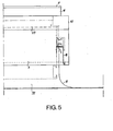
- FIG. 5 shows that the flashings 8 descend beyond the bottom wall 4-5 and that the water return 11 has flanks 52 whose upper edges 53 go up under the flashings 8 at the same height as the noquets, thus ensuring sealing at the bottom of the chassis.
- glazing bead systems directly integral with the flashings, that is to say a common part for 45 and 8 or 51 and 10.
- the springs 43 and 49, as well as the bracket 47, are screwed to the chassis walls in the factory.
- the installation is reduced to the installation of flashings, parts 45 and 51 which clip, and the hood, the noquets and the water return.
- the rim 27 serves to support a seal 54 on which the glass 55 rests protecting the interior of the solar panel.
- the glass 55 is pressed against the seal 54 by glazing beads 56 which get caught in the housing defined by the flanges 20, 22 and their spouts 23 and 24.
- the leg 14 of the profile no longer has recesses 29, but, above and below the level of the groove 35 in which the screw 50 is screwed, two fine horizontal ribs 57 and 58.
- the ribs 57 and 58 define, with the external face of the leg 14, a third U in which can be fixed, by means of screws 50, springs 49 on which a glazing bead 59 is clipped, the upper part of which is identical to the glazing bead 51.
- the front face of the glazing bead 59 is extended, downwards, by an impermeable sheet 60 which replaces the flashing 10 of FIG. 4.
- the drain flap 11 mounts exactly as in Fig. 4. It appears that the profile of FIG.
- the ribs 57 and 58 are broken in the factory, for example with pliers, which makes it possible to find the case of FIG. 3. You can, if necessary, do the same to form a high side of the chassis.
- the ribs 57 and 58 may have a line of least resistance to facilitate their elimination, when necessary.
- branch 17 of the second U is deleted.
- a piece 61 which, in section, has the shape of a U, with a bottom 62, an outer branch 63 and an inner branch 64, which is extended, at right angles, inwards by a flat part 65 parallel to the bottom 62 and relatively long with respect to the width of the bottom 62.
- the bottom 62 is fixed to the branch 16 by screws 66, shown symbolically by a dashed line.
- the part 61 whose component parts are 62, 63, 64 and 65 is only necessary on the upper horizontal part of the chassis and on the upper parts of the oblique parts of the chassis.
- the hood 12 hooks onto it not only in its horizontal part, but also in its lateral parts.
- the part 61 is useless.
- this variant makes it possible to provide a slightly simpler profile, therefore less expensive, than that of FIGS. 2 to 4.
- the part 61 may be such that the part 65 occupies the entire width between the oblique parts of the chassis. In this case, part 65 directly hides certain components of the solar collector which do not contribute to the absorption of solar energy, but must be hidden for aesthetic reasons.
- the internal branch 19 of the second U is also deleted.
- the same part 61 is used as in the variant of FIG. 7. Note that the profile is even simpler than that of FIG. 7.
- a simple strip 69 is provided, the outer edge of which is housed between the bottom 62 and the branch 16 and which is thus fixed against the branch 16 by the same screws 66.
- the glazing bead 68 is wedged under the strip 69 and hung laterally on. the rim 22.
- the strip 69 has an L-shaped section with a descending part 70, starting from the outer edge of 16.
- This descending part 70 can play the role of flashing 8, FIG. 3.
- the part 69-70 it is possible to use the part 69-70, without the part 61.
Landscapes
- Engineering & Computer Science (AREA)
- Physics & Mathematics (AREA)
- Life Sciences & Earth Sciences (AREA)
- Sustainable Development (AREA)
- Sustainable Energy (AREA)
- Thermal Sciences (AREA)
- Chemical & Material Sciences (AREA)
- Combustion & Propulsion (AREA)
- Mechanical Engineering (AREA)
- General Engineering & Computer Science (AREA)
- Roof Covering Using Slabs Or Stiff Sheets (AREA)
Applications Claiming Priority (2)
| Application Number | Priority Date | Filing Date | Title |
|---|---|---|---|
| FR8107004A FR2503223A1 (fr) | 1981-04-02 | 1981-04-02 | Profile de chassis, notamment de capteur solaire, incorporable en toiture |
| FR8107004 | 1981-04-02 |
Publications (1)
| Publication Number | Publication Date |
|---|---|
| EP0062582A1 true EP0062582A1 (fr) | 1982-10-13 |
Family
ID=9257131
Family Applications (1)
| Application Number | Title | Priority Date | Filing Date |
|---|---|---|---|
| EP82400601A Withdrawn EP0062582A1 (fr) | 1981-04-02 | 1982-04-01 | Profilé de châssis, notamment de capteur solaire, incorporable en toiture |
Country Status (2)
| Country | Link |
|---|---|
| EP (1) | EP0062582A1 (OSRAM) |
| FR (1) | FR2503223A1 (OSRAM) |
Cited By (13)
| Publication number | Priority date | Publication date | Assignee | Title |
|---|---|---|---|---|
| EP0424581A1 (en) * | 1989-10-23 | 1991-05-02 | Hirai Engineering Corporation | Roof |
| DE9114555U1 (de) * | 1991-11-22 | 1992-01-16 | Solar Diamant-System GmbH, 4441 Wettringen | Sonnenkollektor |
| EP0417303A4 (en) * | 1989-03-30 | 1992-08-05 | Hirai Engineering Corporation | Roof collecting solar energy |
| EP0674141A3 (de) * | 1994-03-25 | 1996-03-06 | Friedrich Mueller | Sonnenkollektor-Rahmenverblendung. |
| AT2341U1 (de) * | 1997-08-22 | 1998-08-25 | Green One Tec Kanduth Produkti | Profilrahmen für ein gehäuse eines sonnenkollektors |
| EP1043549A3 (de) * | 1999-04-07 | 2001-09-26 | SCHÜCO International KG | Rahmenprofil für einen Sonnenkollektor |
| US6428914B2 (en) | 1999-04-07 | 2002-08-06 | Tdk Corporation | Composite substrate, thin-film electroluminescent device using the substrate, and production process for the device |
| EP1233238A1 (de) * | 2001-02-16 | 2002-08-21 | Wolf GmbH | Rahmenprofil und Solarkollektor |
| EP1102017A3 (de) * | 1999-11-19 | 2003-08-20 | Heinz Grüterich | Anordnung zur Befestigung von Glasflächen enthaltende Dachbauelementen |
| WO2011060485A1 (en) * | 2009-11-18 | 2011-05-26 | First Green Park Pty Ltd | Solar still assembly |
| FR2975474A1 (fr) * | 2011-05-18 | 2012-11-23 | Oseris Ouest Solaire En Renouvelable | Profile pour cadre de support de panneau photovoltaique, cadre de support de panneau photovoltaique, ensemble panneau photovoltaique le comprenant et centrale photovoltaique |
| US20160079911A1 (en) * | 2009-06-11 | 2016-03-17 | Sunpower Corporation | Photovoltaic array with array-roof integration member |
| CN108360756A (zh) * | 2018-05-16 | 2018-08-03 | 蚌埠时代塑业有限公司 | 光伏瓦的上横框型材 |
Families Citing this family (2)
| Publication number | Priority date | Publication date | Assignee | Title |
|---|---|---|---|---|
| AT2532U1 (de) * | 1997-11-28 | 1998-12-28 | Bramac Dachsysteme Internation | Sonnenkollektor |
| US10673373B2 (en) | 2016-02-12 | 2020-06-02 | Solarcity Corporation | Building integrated photovoltaic roofing assemblies and associated systems and methods |
Citations (11)
| Publication number | Priority date | Publication date | Assignee | Title |
|---|---|---|---|---|
| US2851973A (en) * | 1955-06-28 | 1958-09-16 | Owens Illinois Glass Co | Skylight construction |
| FR2149011A5 (OSRAM) * | 1971-08-12 | 1973-03-23 | Lagesse & Neymarc Ets | |
| US3731439A (en) * | 1971-04-19 | 1973-05-08 | Hickman W P Co Inc | Water dam flashing for roof wall |
| DE2436049A1 (de) * | 1974-07-26 | 1976-02-05 | Mueller Alfred | Justiervorrichtung fuer fenster-futter |
| FR2393126A1 (fr) * | 1977-06-01 | 1978-12-29 | Isolation Moderne Ste Indle | Lanterneau encliquetable |
| FR2407438A1 (fr) * | 1977-10-25 | 1979-05-25 | Chatelain Michel | Capteur a air |
| US4165589A (en) * | 1975-10-30 | 1979-08-28 | Carteret Arnold E F De | Reglets and associated components |
| DE2811604A1 (de) * | 1978-03-17 | 1979-09-20 | Dornier System Gmbh | Rahmen |
| US4190999A (en) * | 1978-04-25 | 1980-03-04 | Hampton Ralph C | Locator for vertical reinforcing bars |
| FR2465964A1 (fr) * | 1978-06-29 | 1981-03-27 | Aubes | Circulateur d'air a energie solaire |
| FR2470925A1 (fr) * | 1979-12-03 | 1981-06-12 | Lefebvre Roland | Capteur solaire perfectionne, et procede pour sa fabrication |
Family Cites Families (1)
| Publication number | Priority date | Publication date | Assignee | Title |
|---|---|---|---|---|
| US4190989A (en) * | 1978-11-15 | 1980-03-04 | Albert Sakharoff | Roof flashing system |
-
1981
- 1981-04-02 FR FR8107004A patent/FR2503223A1/fr active Granted
-
1982
- 1982-04-01 EP EP82400601A patent/EP0062582A1/fr not_active Withdrawn
Patent Citations (11)
| Publication number | Priority date | Publication date | Assignee | Title |
|---|---|---|---|---|
| US2851973A (en) * | 1955-06-28 | 1958-09-16 | Owens Illinois Glass Co | Skylight construction |
| US3731439A (en) * | 1971-04-19 | 1973-05-08 | Hickman W P Co Inc | Water dam flashing for roof wall |
| FR2149011A5 (OSRAM) * | 1971-08-12 | 1973-03-23 | Lagesse & Neymarc Ets | |
| DE2436049A1 (de) * | 1974-07-26 | 1976-02-05 | Mueller Alfred | Justiervorrichtung fuer fenster-futter |
| US4165589A (en) * | 1975-10-30 | 1979-08-28 | Carteret Arnold E F De | Reglets and associated components |
| FR2393126A1 (fr) * | 1977-06-01 | 1978-12-29 | Isolation Moderne Ste Indle | Lanterneau encliquetable |
| FR2407438A1 (fr) * | 1977-10-25 | 1979-05-25 | Chatelain Michel | Capteur a air |
| DE2811604A1 (de) * | 1978-03-17 | 1979-09-20 | Dornier System Gmbh | Rahmen |
| US4190999A (en) * | 1978-04-25 | 1980-03-04 | Hampton Ralph C | Locator for vertical reinforcing bars |
| FR2465964A1 (fr) * | 1978-06-29 | 1981-03-27 | Aubes | Circulateur d'air a energie solaire |
| FR2470925A1 (fr) * | 1979-12-03 | 1981-06-12 | Lefebvre Roland | Capteur solaire perfectionne, et procede pour sa fabrication |
Cited By (18)
| Publication number | Priority date | Publication date | Assignee | Title |
|---|---|---|---|---|
| EP0417303A4 (en) * | 1989-03-30 | 1992-08-05 | Hirai Engineering Corporation | Roof collecting solar energy |
| US5406936A (en) * | 1989-03-30 | 1995-04-18 | Hirai Engineering Corporation | Roof |
| US5531049A (en) * | 1989-03-30 | 1996-07-02 | Hirai Engineering Corporation | Roof mounted light transmitting frame |
| EP0424581A1 (en) * | 1989-10-23 | 1991-05-02 | Hirai Engineering Corporation | Roof |
| DE9114555U1 (de) * | 1991-11-22 | 1992-01-16 | Solar Diamant-System GmbH, 4441 Wettringen | Sonnenkollektor |
| EP0674141A3 (de) * | 1994-03-25 | 1996-03-06 | Friedrich Mueller | Sonnenkollektor-Rahmenverblendung. |
| AT2341U1 (de) * | 1997-08-22 | 1998-08-25 | Green One Tec Kanduth Produkti | Profilrahmen für ein gehäuse eines sonnenkollektors |
| US6428914B2 (en) | 1999-04-07 | 2002-08-06 | Tdk Corporation | Composite substrate, thin-film electroluminescent device using the substrate, and production process for the device |
| EP1043549A3 (de) * | 1999-04-07 | 2001-09-26 | SCHÜCO International KG | Rahmenprofil für einen Sonnenkollektor |
| EP1102017A3 (de) * | 1999-11-19 | 2003-08-20 | Heinz Grüterich | Anordnung zur Befestigung von Glasflächen enthaltende Dachbauelementen |
| EP1233238A1 (de) * | 2001-02-16 | 2002-08-21 | Wolf GmbH | Rahmenprofil und Solarkollektor |
| US20160079911A1 (en) * | 2009-06-11 | 2016-03-17 | Sunpower Corporation | Photovoltaic array with array-roof integration member |
| US9716465B2 (en) * | 2009-06-11 | 2017-07-25 | Sunpower Corporation | Photovoltaic array with array-roof integration member |
| WO2011060485A1 (en) * | 2009-11-18 | 2011-05-26 | First Green Park Pty Ltd | Solar still assembly |
| CN102667364A (zh) * | 2009-11-18 | 2012-09-12 | 第一绿色园林私人公司 | 太阳能蒸馏器组件 |
| FR2975474A1 (fr) * | 2011-05-18 | 2012-11-23 | Oseris Ouest Solaire En Renouvelable | Profile pour cadre de support de panneau photovoltaique, cadre de support de panneau photovoltaique, ensemble panneau photovoltaique le comprenant et centrale photovoltaique |
| FR2975475A1 (fr) * | 2011-05-18 | 2012-11-23 | Oseris Ouest Solaire En Renouvelable | Ensemble de support de panneau photovoltaique comprenant un cadre etanche avec des cotes profiles, et centrale correspondante. |
| CN108360756A (zh) * | 2018-05-16 | 2018-08-03 | 蚌埠时代塑业有限公司 | 光伏瓦的上横框型材 |
Also Published As
| Publication number | Publication date |
|---|---|
| FR2503223A1 (fr) | 1982-10-08 |
| FR2503223B1 (OSRAM) | 1983-11-18 |
Similar Documents
| Publication | Publication Date | Title |
|---|---|---|
| EP0062582A1 (fr) | Profilé de châssis, notamment de capteur solaire, incorporable en toiture | |
| FR2923236A1 (fr) | Element d'etancheite pour chassis de panneaux et systeme correspondant | |
| EP0791117B1 (fr) | Dispositif de fixation d'une sous-face d'habillage de debord de toiture | |
| EP2034249B1 (fr) | Installation comprenant une pluralité de panneaux solaires et leur dispositf d'intégration sur un toit | |
| EP2687647A1 (fr) | Dispositif de couverture d'une surface extérieure ou d'un bâtiment type véranda ou pergola et son procédé d'assemblage | |
| CA2414958A1 (fr) | Dispositif de toiture a lames avec aeration | |
| EP3784512B1 (fr) | Joint lecheur de vitre | |
| EP0764749A1 (fr) | Dispositif de support d'un élément en porte à faux vis-à-vis de la façade verticale d'un mur rideau d'un batiment ou construction analogue | |
| FR2800437A1 (fr) | Ensemble constitue d'un support rigide et d'un habillage du support, profile d'habillage et son utilisation pour un tel ensemble | |
| EP0546971B1 (fr) | Dispositif de jonction invisible, notamment pour toiles tendues | |
| FR2967704A1 (fr) | Dispositif d'integration de panneaux, en particulier de panneaux solaires sur une toiture de batiment, et couverture de batiment en faisant application | |
| FR2956681A1 (fr) | Dispositif pour l'integration de panneaux photovoltaiques sur un toit | |
| EP0428921B1 (fr) | Ensemble d'éclairage et/ou de ventilation d'un local couvert comportant une fenêtre de toit associée à une fenêtre de cloison | |
| FR2861410A1 (fr) | Perfectionnement aux toitures de verandas ou de verrieres | |
| FR2557915A1 (fr) | Volet perfectionne destine a faire office de persienne a lames orientables | |
| EP0085632A1 (fr) | Lucarne | |
| FR2970989A1 (fr) | Dispositif support de panneaux photovoltaiques en toiture, antivol | |
| EP2325434B1 (fr) | Coffre-tunnel pourvu d'un rail de liaison pour un dormant | |
| EP0155243A2 (fr) | Ensemble d'éléments pour la mise en oeuvre de couvertures légères, notamment des vérandas | |
| EP1055794A1 (fr) | Fenêtre dont le châssis en bois est associé à un capotage qui protège ses parties exposées | |
| FR2516133A1 (fr) | Procede de couverture d'une toiture d'un edifice utilisant des capteurs solaires | |
| FR2538844A1 (fr) | Cadre de menuiserie avec feuillure a drainage rapide, notamment pour des portes et fenetres | |
| BE892303R (fr) | Profile de rive porteur polyvalent, etanche pour mur-rideau toiture, lanterneau et vitrage simple ou multiple, pouvant comporter des parties ouvrantes | |
| FR2716489A1 (fr) | Dispositif pour la pose d'un vitrage multiple sur un châssis de fenêtre conçu pour ne recevoir qu'une simple vitre. | |
| FR3101098A1 (fr) | Système de blocage volets coulissants. |
Legal Events
| Date | Code | Title | Description |
|---|---|---|---|
| PUAI | Public reference made under article 153(3) epc to a published international application that has entered the european phase |
Free format text: ORIGINAL CODE: 0009012 |
|
| AK | Designated contracting states |
Designated state(s): AT BE CH DE FR GB IT LU NL SE |
|
| 17P | Request for examination filed |
Effective date: 19830331 |
|
| STAA | Information on the status of an ep patent application or granted ep patent |
Free format text: STATUS: THE APPLICATION IS DEEMED TO BE WITHDRAWN |
|
| 18D | Application deemed to be withdrawn |
Effective date: 19840411 |
|
| RIN1 | Information on inventor provided before grant (corrected) |
Inventor name: LAMBLIN, MICHEL Inventor name: LATTES, PHILIPPE |