EP0062384A1 - Vorrichtung zum Ausschneiden eines Gärfutterblockes - Google Patents
Vorrichtung zum Ausschneiden eines Gärfutterblockes Download PDFInfo
- Publication number
- EP0062384A1 EP0062384A1 EP82200405A EP82200405A EP0062384A1 EP 0062384 A1 EP0062384 A1 EP 0062384A1 EP 82200405 A EP82200405 A EP 82200405A EP 82200405 A EP82200405 A EP 82200405A EP 0062384 A1 EP0062384 A1 EP 0062384A1
- Authority
- EP
- European Patent Office
- Prior art keywords
- cutting
- carrying element
- wedge
- ensilage
- pressing member
- Prior art date
- Legal status (The legal status is an assumption and is not a legal conclusion. Google has not performed a legal analysis and makes no representation as to the accuracy of the status listed.)
- Ceased
Links
- 238000005520 cutting process Methods 0.000 title claims abstract description 78
- 230000008878 coupling Effects 0.000 claims description 9
- 238000010168 coupling process Methods 0.000 claims description 9
- 238000005859 coupling reaction Methods 0.000 claims description 9
- 230000000694 effects Effects 0.000 abstract description 4
- 238000010276 construction Methods 0.000 description 1
- 238000000151 deposition Methods 0.000 description 1
- 238000006073 displacement reaction Methods 0.000 description 1
- 239000000463 material Substances 0.000 description 1
Images
Classifications
-
- A—HUMAN NECESSITIES
- A01—AGRICULTURE; FORESTRY; ANIMAL HUSBANDRY; HUNTING; TRAPPING; FISHING
- A01F—PROCESSING OF HARVESTED PRODUCE; HAY OR STRAW PRESSES; DEVICES FOR STORING AGRICULTURAL OR HORTICULTURAL PRODUCE
- A01F25/00—Storing agricultural or horticultural produce; Hanging-up harvested fruit
- A01F25/16—Arrangements in forage silos
- A01F25/20—Unloading arrangements
- A01F25/2027—Unloading arrangements for trench silos
- A01F25/2036—Cutting or handling arrangements for silage blocks
Definitions
- the invention relates to an ensilage cutting device mainly comprising a frame for supporting a substantially horizontal carrying element, for example, a fork and a guide arranged at a distance above the same for a carriage movable along the same and having a cutting member to be driven upwards and downwards.
- a substantially horizontal carrying element for example, a fork and a guide arranged at a distance above the same for a carriage movable along the same and having a cutting member to be driven upwards and downwards.
- the invention has for its object to improve the shape of the cutting member in a manner such that the overall cutting time per unit of length is materially reduced to even 50% of that of the conventional cutting members, which improved cutting effect also contributes to a reduction of the reguired driving power.
- the ensilage cutting device is distinguished in that the cutting member is formed by an elongate blade of wedge-shaped cross-section, in which the angle of the wedge is at the most 30° and preferably 20°.
- the cutting blade is furthermore provided at the tip of the wedge with tines each having two cutting edges extending asymmetrically with respect to the transverse surface of the blade, one cutting edge mainly protruding with respect to a direction of movement. Owing to the protruding position of the cutting edge the tine tends to penetrate further into the material so that cutting movement additionally contributes to the advance movement, which reduces the load of the moment on the carriage along the guide.
- the'other cutting edge of the tine extends parallel or substantially parallel to the vector composed by the velocity vector of one direction of movement and the velocity vector of the carriage.
- the plane of connection of the cutting edges to the side surface of the cutting blade is at an angle of at the most 30 0 , preferably 20° to the prolongation of the side surface.
- the cutting lines are located in the side surface of the wedge-shaped cutting blade.
- the invention furthermore relates to a device of the kind set forth in the preamble which comprises a pressing member acting on the ensilage packet.
- the pressing member is arranged so as to be movable along a substantially rectilinear-path by means of a pivotable rod system.
- the rod system is preferably formed by two rods pivoted to a carrying part of the device, to the free ends of which is pivoted a coupling rod connected with the pressing member.
- the pressing member may be formed by means to push the cut packet of ensilage away from the carrying element and in this case the rod system is pivotally connected near the carrying element with the frame, the pressing member then being movable along a substantially rectilinear path over the carrying element.
- the ensilage can be slipped in a simple manner from the carrying element by depositing the device on said supports and by moving forwards the carriage or tractor carrying the device.
- the pressing member When the pressing member is used as a stamp acting on top of the packet of ensilage to be cut out in order to optimalize the cutting effect of the cutting member in the ensilage, it is preferred to pivot the rod system to the guide of the carriage for the cutting member, the pressing member then being formed by a ram acting on the top of the ensilage.
- the height of the device is limited so that the manoeuverability of the device is enhanced.
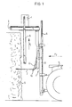
- the device shown in the Figures mainly comprises a framework 1 provided on the underside with a carrying element 2 formed, for example, by a fork and on the top side with a guide 3, along which is guided a carriage 4 having a cutting member 5 adapted to move up and down in the direction of the arrow P1.
- the framework 1 is movable up and down by means of a cylinder 6 along a frame 8 that can be coupled with an agricultural tractor 7.
- a slice can be cut from a stack or ensilage or a silo S by inserting the fork-shaped carrying element 2 in the direction of the arrow P2 at a given height, by moving the cutting member 5 up and down and by moving the carriage 4 along the guide 3.
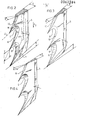
- Figs. 2, 3 and 4 show a few shapes of tines suitable for use on the cutting member 5 in accordance with the invention.
- the cutting member 5 has an elongate structure and in a cross-sectional view it has the shape of a wedge, which is designated in the Figures by A. According to the invention the angle of the wedge is at the most 30°, but preferably 20°.
- the tines located near the tip of the wedge each have two cutting edges 9 and 10 respectively, which have an asymmetrical shape with respect to the transverse plane.
- the cutting edge 9 is preferably disposed in a protruding position with respect to one, for example, downward movement P3 of the cutting blade 5.
- the cutting edge 9 shown in the Figures has a slightly curved shape , it may, as an alternative, be straight.
- the cutting edge 10 extends parallel or substantially parallel to the vector T formed by the velocity vector P of the downward movement P3 and the velocity vector V of the carriage 4 along the guide 3 (see Fig. 2).
- the short lower rim of the cutting blade 5 also extends opposite the direction of movement P3, whilst the cutting edge 11 extends substantially parallel to the line 12 at the cutting edge 9, indicating the medium protruding position of the cutting edge 9.
- the plane of connection W between the cutting edge 9 and 10 respectively and the side face of the wedge-shaped body is at an angle B of at the most 30°, but preferably 20° to the prolongation of the side face of the wedge-shaped body.
- the cutting angle C along the cutting edge on the underside of the blade 5 is also at the most 30°, but preferably 20°.
- the cutting edges 9, 10 are located in the same plane i.e. the longitudinal medium plane of the wedge-shaped body 5.
- the cutting edges 9, 10 are located in one face of the wedge-shaped body 5 i.e. the rear face.
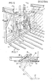
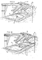
- Fig. 5 is a perspective view of the lower part of the device of Fig. 1; the corresponding parts are designated by the same reference numerals.
- a pressing member 15 is arranged above the carrying element 2, said member 15 being provided on the underside with supports 16 extending across the carrying elment (see also Fig. 1).
- the pressing member 15 is fastened to the end of two coupling rods 17, 18, each of which is pivotally connected with two pivotal rods 19 and 20 respectively.
- the pivotal rods 19, 20 are each pivoted to the framework 1 in a manner such that a pivotal quadrangle is formed.
- a tensile spring 21 is arranged between the coupling rod 18 and one of the pivotal rods 19, 20.
- the pressing member 15 can be used as follows. By lowering the framework 1 along the guide 8 the supports 16 will touch the ground. While driving the tractor forwards, the supports 16 will remain on the ground, whilst the device is drawn on. Therefore, the pressing member 15 will perform a movement with respect to the carrying element 2 and will slip an ensilage slice S received on the carrying element 2 off said carrying element 2.
- the positions of the pivotal joints of the pivotal rods 17, 18, 19 and 20 are selected so that the rod-shaped pressing member 15 moves along a path substantially parallel to the top face of the carrying element 2, as a result of which the supports 16 continue extending across the tines of the carrying element 2 throughout the length of movement of the pressing member 15.
- the slice can be effectively slipped out of the device.
- Fig. 7 shows a similar rod system, but intended for a ram operating on the top side of an ensilage slice.
- the rod system comprises a coupling rod 25, the end of which is provided with the pushing ram 26.
- the coupling rod is connected with two pivotal rods 27 and 28, which are rotatably fastened to a support 29.
- the support 29 is held in place on the inner side of the guide rail 3 of the device.
- a hydraulic ram 30, operating between the support 29 and the arm 27, ensures an upward-downward movement of the pressing ram 26 in a manner such that this movement is substantially rectilinear.
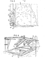
- Figs. 8, 9 and 10 are perspective views of different embodiments of the rams to be used.
- Figs. 8 and 9 each show a ram in the form of a curved tubing 32, which is omnidirectionally pivoted at 32 to the coupling rod 25 of the rod system.
- the shape of the ram 31 substantially matches the cut of the cutting member 5 in the silo S.
- each ram has its own rod system and its own hydraulic ram 30.
- Fig. 9 shows an embodiment in which the pivotal rods 27 of two systems have arranged between them a more or less resilient coupling rod 33, which is engaged by a common. hydraulic ram 30.
- the two rams 31 simultaneously move upwards or downwards.
- an omnidirectionally pivotable joint may be arranged between the rod 33 and the hydraulic ram 30 and the pivotal rods 27 respectively instead of using a resilient rod 33.
- Fig. 10 shows an embodiment in which the rod system having a common hydraulic ram corresponds with that of Fig. 9, though the pushing ram is constructed in the form of two parallel rods 34, 35, between which a leaf spring 36 is arranged. Such a leaf spring enhances the pushing effect of the ram on the top side of the ensilage.
Landscapes
- Life Sciences & Earth Sciences (AREA)
- Environmental Sciences (AREA)
- Shearing Machines (AREA)
- Nonmetal Cutting Devices (AREA)
- Processing Of Stones Or Stones Resemblance Materials (AREA)
Applications Claiming Priority (2)
| Application Number | Priority Date | Filing Date | Title |
|---|---|---|---|
| NL8101629 | 1981-04-01 | ||
| NL8101629A NL8101629A (nl) | 1981-04-01 | 1981-04-01 | Kuilvoersnijinrichting. |
Related Child Applications (2)
| Application Number | Title | Priority Date | Filing Date |
|---|---|---|---|
| EP84201520A Division EP0139338A3 (de) | 1981-04-01 | 1982-03-31 | Silageschneider |
| EP84201520.8 Division-Into | 1982-03-31 |
Publications (1)
| Publication Number | Publication Date |
|---|---|
| EP0062384A1 true EP0062384A1 (de) | 1982-10-13 |
Family
ID=19837274
Family Applications (2)
| Application Number | Title | Priority Date | Filing Date |
|---|---|---|---|
| EP84201520A Withdrawn EP0139338A3 (de) | 1981-04-01 | 1982-03-31 | Silageschneider |
| EP82200405A Ceased EP0062384A1 (de) | 1981-04-01 | 1982-03-31 | Vorrichtung zum Ausschneiden eines Gärfutterblockes |
Family Applications Before (1)
| Application Number | Title | Priority Date | Filing Date |
|---|---|---|---|
| EP84201520A Withdrawn EP0139338A3 (de) | 1981-04-01 | 1982-03-31 | Silageschneider |
Country Status (3)
| Country | Link |
|---|---|
| EP (2) | EP0139338A3 (de) |
| DK (1) | DK146282A (de) |
| NL (1) | NL8101629A (de) |
Cited By (1)
| Publication number | Priority date | Publication date | Assignee | Title |
|---|---|---|---|---|
| CN112753391A (zh) * | 2021-01-04 | 2021-05-07 | 刘怀丹 | 一种青贮料切割搬运装置 |
Citations (4)
| Publication number | Priority date | Publication date | Assignee | Title |
|---|---|---|---|---|
| US3780436A (en) * | 1971-05-24 | 1973-12-25 | Utica Cutlery Co | Device to cut or separate masses of frozen food |
| US4131996A (en) * | 1977-06-27 | 1979-01-02 | Janke William R | Blade for cutting wallboard |
| DE2929782A1 (de) * | 1979-02-21 | 1980-08-28 | Trioliet Mullos | Vorrichtung zum ausschneiden und transportieren eines gaerfutterblockes |
| FR2456464A1 (fr) * | 1979-05-18 | 1980-12-12 | Trioliet Silo Europ | Dispositif pour decouper et transporter un bloc d'ensilage et chassis presseur pour ce dispositif |
Family Cites Families (4)
| Publication number | Priority date | Publication date | Assignee | Title |
|---|---|---|---|---|
| DE2104709A1 (de) * | 1971-02-02 | 1972-08-24 | Bernhard Strautmann & Söhne, 4501 Laer | Gerät zum Entnehmen von Futterportionen aus Flach- oder Fahrsilos |
| BE794963A (fr) * | 1972-02-04 | 1973-05-29 | Bernhard Strautmann & Sohne | Appareil porte par tracteur servant a prelever des quantites de fourrage de silos mobiles |
| DE2817433A1 (de) * | 1978-04-21 | 1979-10-31 | Krone Bernhard Gmbh Maschf | Fahrsilo-entnahmegeraet |
| DE2817901C3 (de) * | 1978-04-24 | 1980-11-06 | Gerhard Duecker Kg, Landmaschinenfabrik, 4424 Stadtlohn | Gerät zum Entnehmen von Futterportionen aus Silos |
-
1981
- 1981-04-01 NL NL8101629A patent/NL8101629A/nl not_active Application Discontinuation
-
1982
- 1982-03-31 EP EP84201520A patent/EP0139338A3/de not_active Withdrawn
- 1982-03-31 EP EP82200405A patent/EP0062384A1/de not_active Ceased
- 1982-03-31 DK DK146282A patent/DK146282A/da not_active Application Discontinuation
Patent Citations (4)
| Publication number | Priority date | Publication date | Assignee | Title |
|---|---|---|---|---|
| US3780436A (en) * | 1971-05-24 | 1973-12-25 | Utica Cutlery Co | Device to cut or separate masses of frozen food |
| US4131996A (en) * | 1977-06-27 | 1979-01-02 | Janke William R | Blade for cutting wallboard |
| DE2929782A1 (de) * | 1979-02-21 | 1980-08-28 | Trioliet Mullos | Vorrichtung zum ausschneiden und transportieren eines gaerfutterblockes |
| FR2456464A1 (fr) * | 1979-05-18 | 1980-12-12 | Trioliet Silo Europ | Dispositif pour decouper et transporter un bloc d'ensilage et chassis presseur pour ce dispositif |
Cited By (1)
| Publication number | Priority date | Publication date | Assignee | Title |
|---|---|---|---|---|
| CN112753391A (zh) * | 2021-01-04 | 2021-05-07 | 刘怀丹 | 一种青贮料切割搬运装置 |
Also Published As
| Publication number | Publication date |
|---|---|
| DK146282A (da) | 1982-10-02 |
| EP0139338A2 (de) | 1985-05-02 |
| EP0139338A3 (de) | 1985-11-27 |
| NL8101629A (nl) | 1982-11-01 |
Similar Documents
| Publication | Publication Date | Title |
|---|---|---|
| US4414793A (en) | Flexible crop harvesting header | |
| US3683601A (en) | Mowing mechanisms | |
| US4565056A (en) | Self-propelled harvester thresher | |
| US5052098A (en) | Means for removing wires from bales in particular waste paper bales | |
| WO2004085115B1 (fr) | Machine pour grouper des produits tels que de l’herbe | |
| EP0062384A1 (de) | Vorrichtung zum Ausschneiden eines Gärfutterblockes | |
| CN200994285Y (zh) | 甘蔗收割机切稍装置 | |
| KR900000929A (ko) | 연료봉 절단장치 | |
| DE2659826C2 (de) | Maschine zum Laden und Fördern losen Materials | |
| US4489675A (en) | Scraper assembly | |
| US4341354A (en) | Device for cutting out and transporting a silage block | |
| US4316508A (en) | Automatic ripper reset mechanism | |
| US4834581A (en) | Root cutting cable laying plow | |
| US5285856A (en) | Mechanical suspension device for piler of sugar cane loaders | |
| CN109496530A (zh) | 自调式甜菜切顶装置 | |
| US2793488A (en) | Mower bar with oscillating cutter elements | |
| EP0044580B1 (de) | Zusätzliche rotierende Schneidmesser für Selbstladewagen | |
| CN209918775U (zh) | 双面弹簧网剪切机构 | |
| JP3002543U (ja) | 人参収穫機における茎葉誘導切断装置 | |
| GB2125661A (en) | Hand tool | |
| JP3263127B2 (ja) | 歩行型根菜類収穫機 | |
| US4490967A (en) | Apparatus for lifting crops | |
| JP2905040B2 (ja) | 抜取り収穫機の収穫部構造 | |
| CN219228425U (zh) | 玉米收获机的切刀组件 | |
| WO1993018640A1 (en) | Apparatus for dividing bales into pieces |
Legal Events
| Date | Code | Title | Description |
|---|---|---|---|
| PUAI | Public reference made under article 153(3) epc to a published international application that has entered the european phase |
Free format text: ORIGINAL CODE: 0009012 |
|
| AK | Designated contracting states |
Designated state(s): BE DE FR GB NL |
|
| 17P | Request for examination filed |
Effective date: 19830407 |
|
| STAA | Information on the status of an ep patent application or granted ep patent |
Free format text: STATUS: THE APPLICATION HAS BEEN REFUSED |
|
| 18R | Application refused |
Effective date: 19860424 |
|
| RIN1 | Information on inventor provided before grant (corrected) |
Inventor name: PRINS, NICOLAAS Inventor name: WESTSTRATE, MARINUS HENDRIKUS Inventor name: VISSERS, HERMANUS HENDRIK |