EP0062216B1 - Method of making funnel-type filter elements, with an opening aid, and device for carrying out that method - Google Patents
Method of making funnel-type filter elements, with an opening aid, and device for carrying out that method Download PDFInfo
- Publication number
- EP0062216B1 EP0062216B1 EP82102350A EP82102350A EP0062216B1 EP 0062216 B1 EP0062216 B1 EP 0062216B1 EP 82102350 A EP82102350 A EP 82102350A EP 82102350 A EP82102350 A EP 82102350A EP 0062216 B1 EP0062216 B1 EP 0062216B1
- Authority
- EP
- European Patent Office
- Prior art keywords
- filter
- strips
- strip
- filter inserts
- perforated
- Prior art date
- Legal status (The legal status is an assumption and is not a legal conclusion. Google has not performed a legal analysis and makes no representation as to the accuracy of the status listed.)
- Expired
Links
- 238000000034 method Methods 0.000 title claims abstract description 34
- 238000004519 manufacturing process Methods 0.000 title claims abstract description 21
- 239000000463 material Substances 0.000 claims abstract description 48
- 238000002360 preparation method Methods 0.000 claims abstract description 3
- 239000002699 waste material Substances 0.000 claims description 3
- 238000004806 packaging method and process Methods 0.000 claims description 2
- 241000376353 Stips Species 0.000 claims 1
- 238000004049 embossing Methods 0.000 description 11
- 238000005520 cutting process Methods 0.000 description 5
- 238000004080 punching Methods 0.000 description 2
- 208000001840 Dandruff Diseases 0.000 description 1
- 235000013361 beverage Nutrition 0.000 description 1
- 238000005096 rolling process Methods 0.000 description 1
Images

Classifications
-
- A—HUMAN NECESSITIES
- A47—FURNITURE; DOMESTIC ARTICLES OR APPLIANCES; COFFEE MILLS; SPICE MILLS; SUCTION CLEANERS IN GENERAL
- A47J—KITCHEN EQUIPMENT; COFFEE MILLS; SPICE MILLS; APPARATUS FOR MAKING BEVERAGES
- A47J31/00—Apparatus for making beverages
- A47J31/06—Filters or strainers for coffee or tea makers ; Holders therefor
- A47J31/08—Paper filter inlays therefor to be disposed after use
-
- B—PERFORMING OPERATIONS; TRANSPORTING
- B31—MAKING ARTICLES OF PAPER, CARDBOARD OR MATERIAL WORKED IN A MANNER ANALOGOUS TO PAPER; WORKING PAPER, CARDBOARD OR MATERIAL WORKED IN A MANNER ANALOGOUS TO PAPER
- B31F—MECHANICAL WORKING OR DEFORMATION OF PAPER, CARDBOARD OR MATERIAL WORKED IN A MANNER ANALOGOUS TO PAPER
- B31F5/00—Attaching together sheets, strips or webs; Reinforcing edges
- B31F5/02—Attaching together sheets, strips or webs; Reinforcing edges by crimping or slotting or perforating
- B31F5/022—Attaching together sheets, strips or webs; Reinforcing edges by crimping or slotting or perforating using a rotary tool
-
- B—PERFORMING OPERATIONS; TRANSPORTING
- B31—MAKING ARTICLES OF PAPER, CARDBOARD OR MATERIAL WORKED IN A MANNER ANALOGOUS TO PAPER; WORKING PAPER, CARDBOARD OR MATERIAL WORKED IN A MANNER ANALOGOUS TO PAPER
- B31B—MAKING CONTAINERS OF PAPER, CARDBOARD OR MATERIAL WORKED IN A MANNER ANALOGOUS TO PAPER
- B31B2155/00—Flexible containers made from webs
- B31B2155/001—Flexible containers made from webs by folding webs longitudinally
- B31B2155/0012—Flexible containers made from webs by folding webs longitudinally having their openings facing in the direction of movement
-
- B—PERFORMING OPERATIONS; TRANSPORTING
- B31—MAKING ARTICLES OF PAPER, CARDBOARD OR MATERIAL WORKED IN A MANNER ANALOGOUS TO PAPER; WORKING PAPER, CARDBOARD OR MATERIAL WORKED IN A MANNER ANALOGOUS TO PAPER
- B31B—MAKING CONTAINERS OF PAPER, CARDBOARD OR MATERIAL WORKED IN A MANNER ANALOGOUS TO PAPER
- B31B2155/00—Flexible containers made from webs
- B31B2155/002—Flexible containers made from webs by joining superimposed webs, e.g. with separate bottom webs
-
- B—PERFORMING OPERATIONS; TRANSPORTING
- B31—MAKING ARTICLES OF PAPER, CARDBOARD OR MATERIAL WORKED IN A MANNER ANALOGOUS TO PAPER; WORKING PAPER, CARDBOARD OR MATERIAL WORKED IN A MANNER ANALOGOUS TO PAPER
- B31B—MAKING CONTAINERS OF PAPER, CARDBOARD OR MATERIAL WORKED IN A MANNER ANALOGOUS TO PAPER
- B31B2160/00—Shape of flexible containers
- B31B2160/30—Shape of flexible containers pointed or tapered
Definitions
- the invention relates to a process for the production of funnel-shaped filter inserts with an opening aid for the preparation of brewing beverages, in which a filter material web, after it has been removed from a roll of material, is continuously rotated at certain intervals to perform the opening aid, then folded over its entire length, then at certain intervals with embossing for Velcro, e.g. B. a bottom and a side edge, the filter inserts and finally cut to remove the filter inserts.
- a filter material web after it has been removed from a roll of material, is continuously rotated at certain intervals to perform the opening aid, then folded over its entire length, then at certain intervals with embossing for Velcro, e.g. B. a bottom and a side edge, the filter inserts and finally cut to remove the filter inserts.
- the filter insert thus produced has a trapezoidal shape which is held together by embossing on a bottom edge and on a side edge, whereas the second side edge consists of a folded edge.
- the opening aid is formed by a semicircular protrusion which projects beyond the essentially curved filter insert side.
- This type of filter insert has proven itself in practice. However, it is difficult to increase the production figures of the filter inserts produced in this way with such a method.
- Such struts are on the one hand relatively narrow limits due to the moments of inertia of the individual machine elements and the limited tensile strength of the material web.
- the object of the invention is to create a method of the type mentioned at the beginning with which a considerable increase in productivity is nevertheless possible without increasing the dynamic load on the material web on the one hand and the production device on the other hand.
- a second filter material web is initially guided congruently to the first filter material web and is punched together with it, that the perforated filter material webs are then pulled apart, separately folded and separately provided with embossings, and that they are then congruently brought together and cut together will.
- the material webs after being provided with the embossments, are placed against one another with their sides of the filter inserts having the opening aid.
- the material webs are stamped with the embossing devices at the moment of their removal.
- an additional removal device made of one or more pairs of transport rollers can be dispensed with, as a result of which the overall transport path is shortened.
- a new device for carrying out the method according to the invention is characterized in that a web edge control device having a plurality of roller pairs, on the one hand, and the rotary punch, on the other hand, and a folding device are arranged after the punch, above and below the transport plane of the two congruently guided material webs.
- the web edge control device ensures an exactly congruent inflow of the two initially separate material webs to the punching machine, on which both material webs are jointly provided with the corresponding perforations for making the opening aid in a single punching process.
- the two now perforated material webs are pulled apart in a plane approximately perpendicular to the transport plane and folded in separately arranged folding devices.
- the folding device for the material web lying above is located above and the folding device for the material web lying below is located at approximately the same location below the transport plane.
- the embossing devices each consisting of a pair of embossing rollers, are arranged in a manner known per se, which at the same time form a pull-off device for the folded material webs from the folding device.
- the new device 1 essentially consists of two rolling devices 2, 3, on each of which a material roll 4, 5 is located. This is followed by a web edge control device provided with the global reference number 6, to which u. a. the roller pairs 7, 8 and the individual rollers 9, 10 belong.
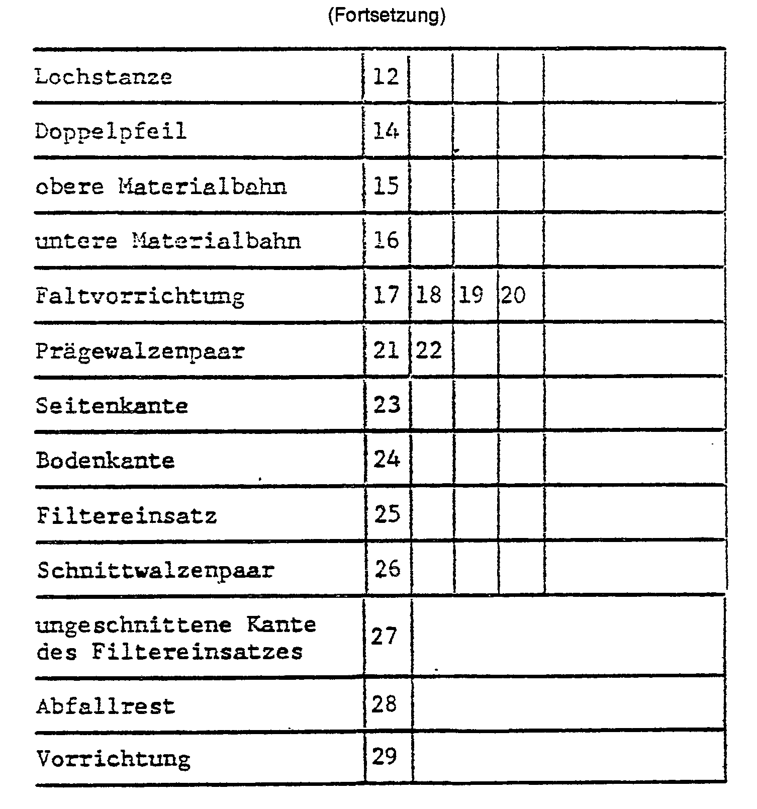
- a hole punch 12 is arranged behind the web edge control device 6 in the transport direction of the arrow 11. Behind the punch 12 there is a pair of rollers 13 which can be moved in the direction of the double arrow 14 in order to be able to compensate for differences in assignment of the upper material web 15 to the lower material web 16.
- the folding device 17 is arranged above the transport plane located approximately in the direction of the double arrow 14 and the second folding device 18 is arranged below the transport plane.
- These folding devices essentially consist of a board with a triangular tip, over which the middle of each material web 15, 16 is pulled and thereby folded.
- a pair of folding rods 19, 20 is directly associated with the tip of this board, through which the folded upper and lower material web 15, 16 is pulled.
- a pair of embossing rollers 21, 22 is attached directly behind these pairs of folding bars 19, 20.
- the two pairs of embossing rollers 21, 22 simultaneously serve as take-off rollers for the folded paper web from the folding devices 17, 18, 19, 20.
- the filter inserts 25 of the filter material webs 15, which are provided separately with the required embossments on each side edge 23 and on the bottom edge 24 , 16 are then brought together again and cut together by the pair of cutting rollers 26.
- the uncut edge 27 of the filter inserts corresponds to the folded edge of the two material webs 15, 16.
- the individual filter inserts 25 are separated from the remaining waste 28 of the upper and lower material webs 15, 16.
- the device with which this procedure is carried out is schematically provided with the reference number 29. Thereafter, the congruently superimposed filter inserts are separated from one another and fanned out at an even distance from one another. This process is called dandruff. After scaling, the individual filter inserts 25 are fed to a packaging device, not shown.
- Both the method and the device are essentially characterized in that all manufacturing processes that can be carried out jointly for both material webs 15, 16 are actually carried out together, and that only those manufacturing processes that are not carried out jointly due to the new method can be done separately. In this sense, it means a worse imitation of the invention if, for example, each material web 15, 16 is assigned its own hole punch and its own cutting rollers 26.
Landscapes
- Engineering & Computer Science (AREA)
- Food Science & Technology (AREA)
- Mechanical Engineering (AREA)
- Folding Of Thin Sheet-Like Materials, Special Discharging Devices, And Others (AREA)
- Making Paper Articles (AREA)
- Machines For Manufacturing Corrugated Board In Mechanical Paper-Making Processes (AREA)
- Apparatus For Making Beverages (AREA)
- Containers And Plastic Fillers For Packaging (AREA)
- Sampling And Sample Adjustment (AREA)
Abstract
Description
Die Erfindung betrifft ein Verfahren zur Herstellung von trichterförmigen Filtereinsätzen mit einer Öftnungshilfe zur Zubereitung von Aufbrühgetränken, bei dem eine Filtermaterialbahn nach ihrem Abzug von einer Materialrolle kontinuierlich rotativ in bestimmten Abständen zur Ausführung der Öffnungshilfe gelocht, hiernach über ihre gesamte Länge gefaltet, sodann in bestimmten Abständen mit Prägungen zur Zusammenklettung, an z. B. einer Boden- und einer Seitenkante, der Filtereinsätze versehen und schließklich zur Herauslösung der Filtereinsätze geschnitten wird.The invention relates to a process for the production of funnel-shaped filter inserts with an opening aid for the preparation of brewing beverages, in which a filter material web, after it has been removed from a roll of material, is continuously rotated at certain intervals to perform the opening aid, then folded over its entire length, then at certain intervals with embossing for Velcro, e.g. B. a bottom and a side edge, the filter inserts and finally cut to remove the filter inserts.
Bei einem durch offenkundige Vorbenutzung bekanntgewordenen Verfahren dieser Art weist der damit gefertigte Filtereinsatz eine trapezoedale Form auf, der an einer Boden- und an einer Seitenkante durch eine Prägung zusammengehalten wird, wohingegen die zweite Seitenkante aus einer Faltkante besteht. Die Öffnungshilfe wird von einem halbkreisförmigen Überstand gebildet, der über die im wesentlichen bogenförmig verlaufende Filtereinsatzseite hinausragt. Diese Art der Filtereinsätze hat sich in der Praxis bewährt. Schwierig ist jedoch, mit einem solchen Verfahren die Produktionsziffern der auf diese Weise gefertigen Filtereinsätze zu erhöhen. Einem solchen Streben sind aufgrund der Massenträgheitsmomente der einzelnen Maschinenelemente einerseits sowie der begrenzten Zugfestigkeit der Materialbahn relativ enge Grenzen gesetzt. Hinzu kommt, daß eine Erhöhung der Produktionsziffer zwangsläufig mit einer erhöhten Geschwindigkeit und damit mit einer erhöhten dynamischen Belastung der einzelnen Maschinenelement verknüpft ist. Eine erhöhte Belastung wiederum bedeutet einen erhöhten Verschleiß und damit eine geringere Lebensdauer der betreffenden Fertigungsvorrichtung. Ein Verfahren der oben erwähnten Art ist auch aus der FR-A-2 349 438 bekannt.In a method of this type which has become known through public prior use, the filter insert thus produced has a trapezoidal shape which is held together by embossing on a bottom edge and on a side edge, whereas the second side edge consists of a folded edge. The opening aid is formed by a semicircular protrusion which projects beyond the essentially curved filter insert side. This type of filter insert has proven itself in practice. However, it is difficult to increase the production figures of the filter inserts produced in this way with such a method. Such struts are on the one hand relatively narrow limits due to the moments of inertia of the individual machine elements and the limited tensile strength of the material web. In addition, an increase in the production figure is inevitably linked to an increased speed and thus an increased dynamic load on the individual machine elements. An increased load in turn means increased wear and thus a shorter service life of the manufacturing device in question. A method of the type mentioned above is also known from FR-A-2 349 438.
Von diesem Stand der Technik ausgehend liegt der Erfindung die Aufgabe zugrunde, ein Verfahren der eingangs genannten Art zu schaffen, mit welchem ohne Erhöhung der dynamischen Belastung der Materialbahn einerseits und der Fertigungsvorrichtung andererseits gleichwohl eine erhebliche Erhöhung der Produktivität möglich ist.On the basis of this prior art, the object of the invention is to create a method of the type mentioned at the beginning with which a considerable increase in productivity is nevertheless possible without increasing the dynamic load on the material web on the one hand and the production device on the other hand.
Diese Aufgabe wird erfindungsgemäß dadurch gelöst, daß eine zweite Filtermaterialbahn zunächst kongruent zur ersten Filtermaterialbahn geführt und gemeinsam mit ihr gelocht wird, daß hiernach die gelochten Filtermaterialbahnen auseinandergezogen, getrennt gefaltet und getrennt mit Prägungen versehen werden, und daß sie hiernach wiederum kongruent zusammengeführt und gemeinsam geschnitten werden. Mit einem solchen Verfahren ist es nicht nur möglich, selbst bei geringerer Transportgeschwindigkeit der beiden Materialbahnen gleichwohl eine erhebliche Erhöhung der Produktionsziffer der damit gefertigten Filtereinsätze zu schaffen, sondern bei gleicher Geschwindigkeit dieses Verfahrens zum vorbekannten Verfahren wird sogar eine Verdoppelung der Produktionsziffer erzielt. Durch die volle Integration von teilweise getrennt durchzuführenden Fertigungsvorgängen in den Gesamtfertigungsvorgang wird ein optimales Ergebnis erzielt. Das ist insofern überraschend, wie zwei räumliche Gebilde von Filtereinsätzen in verschiedenen Materialbahnen exakt zur Lochung zusammengeführt, hiernach wiederum voneinander getrennt und nach der Prägung wiederum exakt aufeinanderliegend von einer einzigen Schneidvorrichtung gemeinsam geschnitten werden.This object is achieved according to the invention in that a second filter material web is initially guided congruently to the first filter material web and is punched together with it, that the perforated filter material webs are then pulled apart, separately folded and separately provided with embossings, and that they are then congruently brought together and cut together will. With such a method, it is not only possible to achieve a significant increase in the production number of the filter inserts produced with it, even with a lower transport speed of the two material webs, but with the same speed of this method as the previously known method, the production number is even doubled. An optimal result is achieved by fully integrating partially separate manufacturing processes into the overall manufacturing process. This is surprising insofar as two spatial structures of filter inserts in different material webs are brought together exactly for perforation, then separated from each other again and, after embossing, cut together in a precisely lying manner by a single cutting device.
Nach einer vorteilhaften Weiterbildung der Erfindung werden die Materialbahnen nach Versehung mit den Prägungen mit ihren die Öffungshilfe aufweisenden Seiten der Filtereinsätze aneinander gelegt.According to an advantageous development of the invention, the material webs, after being provided with the embossments, are placed against one another with their sides of the filter inserts having the opening aid.
Ferner werden die Materialbahnen im Augenblick ihres Abzuges von den Faltvorrichtungen mit den Prägungen versehen. Dadurch kann eine zusätzliche Abzugseinrichtung aus einem oder mehreren Transportwalzenpaaren entbehrlich werden, wodurch der Gesamttransportweg verkürzt wird.Furthermore, the material webs are stamped with the embossing devices at the moment of their removal. As a result, an additional removal device made of one or more pairs of transport rollers can be dispensed with, as a result of which the overall transport path is shortened.
Bekannte Vorrichtungen zur Durchführung des gattungsgemäßen Verfahrens weisen eine rotative Lochstanze, eine Faltvorrichtung, eine Präge- und eine Schnitteinrichtung auf. Eine neue Vorrichtung zur Durchführung der erfindungsgemäßen Verfahrens ist dadurch gekennzeichnet, daß zwischen den Materialrollen einerseits und der rotativen Lochstanze andererseits eine mehrere Rollenpaare aufweisende Bahnkanten-Steuerungseinrichtung und nach der Lochstanze oberhalb und unterhalb der Transportebene der beiden kongruent geführten Materialbahnen je eine Faltvorrichtung angeordnet sind. Dabei sorgt die Bahnkanten-Steuerungseinrichtung für einen exakt kongruenten Zulauf der beiden zunächst getrennten Materialbahnen zu der Lochstanze, an welcher beide Materialbahnen gemeinsam in einem einzigen Stanzvorgang mit den entsprechenden Lochungen für die Anfertigung der Öftnungshilfe versehen werden. Hiernach werden die beiden nunmehr gelochten Materialbahnen in eine etwa senkrecht zur Transportebene verlaufenden Ebene auseinandergezogen und in getrennt angeordneten Faltvorrichtungen gefaltet. Dabei befindet sich die Faltvorrichtung für die oben liegende Materialbahn oberhalb und die Faltvorrichtung für die unten liegende Materialbahn unterhalb der Transportebene an etwa gleicher Stelle. Hiernach sind die in an sich bekannter Weise aus je einem Prägewalzenpaar bestehenden Prägeeinrichtungen angeordnet, die zugleich eine Abzugsvorrichtung der gefalteten Materialbahnen von der Faltvorrichtung bilden.Known devices for performing the generic method have a rotary punch, a folding device, an embossing and a cutting device. A new device for carrying out the method according to the invention is characterized in that a web edge control device having a plurality of roller pairs, on the one hand, and the rotary punch, on the other hand, and a folding device are arranged after the punch, above and below the transport plane of the two congruently guided material webs. The web edge control device ensures an exactly congruent inflow of the two initially separate material webs to the punching machine, on which both material webs are jointly provided with the corresponding perforations for making the opening aid in a single punching process. Thereafter, the two now perforated material webs are pulled apart in a plane approximately perpendicular to the transport plane and folded in separately arranged folding devices. The folding device for the material web lying above is located above and the folding device for the material web lying below is located at approximately the same location below the transport plane. According to this, the embossing devices, each consisting of a pair of embossing rollers, are arranged in a manner known per se, which at the same time form a pull-off device for the folded material webs from the folding device.
Das neue Verfahren wird nachfolgend anhand einer Zeichnung beschrieben, auf welcher eine schematische, perspektivische Ansicht der erfindungsgemäßen Vorrichtung abgebildet ist.The new method is described below with reference to a drawing, on which a schematic, perspective view of the device according to the invention is shown.
Die neue Vorrichtung 1 besteht im wesentlichen aus zwei Abrollvorrichtungen 2, 3, auf denen sich jeweils eine Materialrolle 4, 5 befindet. Hieran schließt sich eine global mit der Bezugsziffer 6 versehene Bahnkanten-Steuerungseinrichtung an, zu der u. a. die Walzenpaare 7, 8 sowie die Einzelwalzen 9, 10 gehören.The new device 1 essentially consists of two
In Transportrichtung des Pfeiles 11 ist hinter der Bahnkanten-Steuerungseinrichtung 6 eine Lochstanze 12 angeordnet. Hinter der Lochstanze 12 befindet sich ein Walzenpaar 13, welches in Richtung des Doppelpfeiles 14 bewegbar ist, um Zuordnungsunterschiede der oberen Materialbahn 15 zur unteren Materialbahn 16 ausgleichen zu können. Oberhalb der etwa in Richtung des Doppelpfeiles 14 befindlichen Transportebene ist die Faltvorrichtung 17 und unterhalb der Transportebene die zweite Faltvorrichtung 18 angeordnet. Diese Faltvorrichtungen bestehen im wesentlichen aus einem Brett mit dreieckförmiger Spitze, über welche exakt die Mitte einer jeden Materialbahn 15, 16 gezogen und dadurch gefaltet wird. Der Spitze dieses Brettes ist unmittelbar jeweils ein Faltstangenpaar 19, 20 zugeordnet, durch welche die gefaltete obere und untere Materialbahn 15, 16 gezogen wird. In Transportverlauf unmittelbar hinter diesen Faltstangenpaaren 19, 20 ist jeweils ein Prägewalzenpaar 21, 22 angebracht. Die beiden Prägewalzenpaare 21, 22 dienen im vorliegenden Fall gleichzeitig als Abzugswalzen der gefalteten Papierbahn von den Faltvorrichtungen 17, 18, 19, 20. Die getrennt mit den erforderlichen Prägungen an jeweils einer Seitenkante 23, und an der Bodenkante 24 versehenen Filtereinsätze 25 der Filtermaterialbahnen 15, 16 werden sodann wieder zusammengeführt und gemeinsam von dem Schnittwalzenpaar 26 geschnitten. Die ungeschnittene Kante 27 der Filtereinsätze entspricht der Faltkante der beiden Materialbahnen 15, 16.A
Nach dem Schnitt werden die einzelnen Filtereinsätze 25 vom verbleibenden Abfallrest 28 der oberen und der unteren Materialbahnen 15, 16 getrennt. Die Vorrichtung, mit der dieser Verfahrensgang durchgeführt wird, ist schematisch mit der Bezugsziffer 29 versehen. Danach werden die kongruent aufeinanderliegenden Filtereinsätze voneinander getrennt und dabei in gleichmäßigem Abstand zueinander aufgefächert. Dieser Vorgang wird als Schuppen bezeichnet. Nach der Schuppung werden die einzelnen Filtereinsätze 25 einer nicht dargestellten Verpackungseinrichtung zugeführt.After the cut, the
Durch das Zusammenführen zweier Materialbahnen 15, 16, deren erneutes Trennen zum Falten und Prägen und deren endgültige Zusammenführung zum Schneiden, Trennen des Abfallrestes und Schuppen der Filtereinsätze, wird ein Verfahren geschaffen, durch welches selbst bei verminderten Produktionsgeschwindigkeiten gegenüber dem einbahnigen Verfahren eine erhöhte Produktionsziffer erzielt wird. Bei zum einbahnigen Verfahren gleicher Transportgeschwindigkeit der Materialbahnen ergibt sich sogar eine Verdoppelung der Produktionsziffer. Dabei ist wesentlich, daß nunmehr innerhalb eines relativ großen Bereiches der Produktionsziffer das neue Verfahren und auch die neue Vorrichtung an entsprechende Produktionswünsche elastisch angepaßt werden kann. Dabei bedeutet eine geringere Produktionsgeschwindigkeit gleichzeitig auch eine größere Lebensdauer der gesamten Vorrichtung.By merging two
Dabei ist sowohl das Verfahren als auch die Vorrichtung im wesentlichen dadurch gekennzeichnet, daß sämtliche Fertigungsvorgänge, die für beide Materialbahnen 15, 16 gemeinsam durchgeführt werden können, auch tatsächlich gemeinsam erfolgen, und daß lediglich diejenigen Fertigungsvorgänge, die aufgrund des neuen Verfahrens nicht gemeinsam durchgeführt werden können, getrennt erfolgen. In diesem Sinne bedeutet es eine verschlechterte Nachahmung der Erfindung, wenn beispielsweise einer jeden Materialbahn 15, 16 eine eigene Lochstanze und eigene Schnittwalzen 26 zugeordnet werden.Both the method and the device are essentially characterized in that all manufacturing processes that can be carried out jointly for both
Die Erfindung wurde vorstehend am Beispiel eines zweibahnigen Verfahrens beschrieben. Es versteht sich jedoch, daß erfindungsgemäß auch ein Verfahren mit drei und mehr Materialbahnen möglich ist, zumal ein solches stets mindestens auch ein zweibahniges Verfahren enthält.The invention was described above using the example of a two-lane method. However, it goes without saying that, according to the invention, a method with three or more material webs is also possible, especially since such a method always contains at least one two-web method.
« Verfahren zur Herstellung von trichterförmigen Filtereinsätzen mit einer Öffnungshilfe sowie Vorrichtung zur Durchführung dieses Verfahrens »

Claims (7)
Priority Applications (1)
| Application Number | Priority Date | Filing Date | Title |
|---|---|---|---|
| AT82102350T ATE20450T1 (en) | 1981-04-07 | 1982-03-22 | PROCESS FOR THE MANUFACTURE OF FUNNEL-SHAPED FILTER INSERT WITH AN OPENING AID AND DEVICE FOR CARRYING OUT THIS PROCESS. |
Applications Claiming Priority (2)
| Application Number | Priority Date | Filing Date | Title |
|---|---|---|---|
| DE3113951A DE3113951C2 (en) | 1981-04-07 | 1981-04-07 | Method and device for the production of funnel-shaped filter inserts with opening aids |
| DE3113951 | 1981-04-07 |
Publications (3)
| Publication Number | Publication Date |
|---|---|
| EP0062216A2 EP0062216A2 (en) | 1982-10-13 |
| EP0062216A3 EP0062216A3 (en) | 1983-08-03 |
| EP0062216B1 true EP0062216B1 (en) | 1986-06-18 |
Family
ID=6129542
Family Applications (1)
| Application Number | Title | Priority Date | Filing Date |
|---|---|---|---|
| EP82102350A Expired EP0062216B1 (en) | 1981-04-07 | 1982-03-22 | Method of making funnel-type filter elements, with an opening aid, and device for carrying out that method |
Country Status (3)
| Country | Link |
|---|---|
| EP (1) | EP0062216B1 (en) |
| AT (1) | ATE20450T1 (en) |
| DE (1) | DE3113951C2 (en) |
Cited By (1)
| Publication number | Priority date | Publication date | Assignee | Title |
|---|---|---|---|---|
| US20100216618A1 (en) * | 2008-02-26 | 2010-08-26 | Gfm Maschinenbau Gmbh | Method and device for producing filter inserts |
Families Citing this family (6)
| Publication number | Priority date | Publication date | Assignee | Title |
|---|---|---|---|---|
| DE3728888A1 (en) * | 1987-08-29 | 1989-03-09 | Bentz & Sohn Melitta | METHOD FOR PRODUCING SECTIONS FROM AN ELASTIC PAPER, PREFERABLY A CREPED PAPER, AND APPARATUS FOR IMPLEMENTING THE METHOD |
| DE4435532A1 (en) * | 1994-10-05 | 1996-04-11 | Mann & Hummel Filter | Process for the production of filters |
| DE29702546U1 (en) * | 1997-02-14 | 1998-06-10 | Melitta Haushaltsprodukte GmbH & Co. KG, 32427 Minden | Filter paper insert |
| DE19961961C2 (en) * | 1999-12-22 | 2001-12-13 | Melitta Haushaltsprodukte | Embossing press for producing embossed seams |
| US6440256B1 (en) * | 2000-06-20 | 2002-08-27 | Keurig, Incorporated | Method of forming and inserting filter elements in cup-shaped containers |
| DE50005520D1 (en) * | 2000-07-15 | 2004-04-08 | Melitta Haushaltsprodukte | Process for the production of bag-like filter paper inserts |
Family Cites Families (13)
| Publication number | Priority date | Publication date | Assignee | Title |
|---|---|---|---|---|
| US1503155A (en) * | 1921-05-09 | 1924-07-29 | Haas Adrian | Machine for the manufacture of envelopes |
| DE951543C (en) * | 1941-12-06 | 1956-10-31 | Michael Hoerauf | Device for making handkerchiefs, napkins, etc. from cellulose webs |
| US2511303A (en) * | 1946-09-09 | 1950-06-13 | Benj C Betner Company | Window bag and method and apparatus for making same |
| GB1038243A (en) * | 1964-03-02 | 1966-08-10 | Beasley French & Company Ltd | Improvements in or relating to plain and satchel bag machines |
| SE339387B (en) * | 1965-05-07 | 1971-10-04 | Welin Berger G | |
| DE1934273U (en) * | 1965-08-07 | 1966-03-10 | Bentz & Sohn Melitta | POCKET-SHAPED FILTER INSERT MADE OF FILTER PAPER FOR FILTER FUNNELS FOR THE PRODUCTION OF BREWING BEVERAGES. |
| DE1293976B (en) * | 1965-08-10 | 1969-04-30 | Honsel Karl Heinz | Process for the production of filter bags |
| DE2034309A1 (en) * | 1970-07-10 | 1972-01-27 | Jacobs Joh & Co | Filter insert for filter funnel |
| US3800954A (en) * | 1972-05-03 | 1974-04-02 | Star Filter Co | Coffee filter and method of making same |
| DE2221831C2 (en) * | 1972-05-04 | 1974-06-27 | Melitta-Werke Bentz & Sohn, 4950 Minden | Filter vessel with filter bag for the production of aroma extracts |
| DE2256242C3 (en) * | 1972-11-16 | 1979-01-04 | Windmoeller & Hoelscher, 4540 Lengerich | Method and device for the production of gusseted bags |
| FR2349438A1 (en) * | 1976-04-30 | 1977-11-25 | Guilliet Ets | Paper filter for coffee making - has two overlying strips with filter sides and base formed by pressing before cutting out |
| DE2702358C2 (en) * | 1977-01-21 | 1979-03-29 | Bikoma Gmbh Spezialmaschinenfabrik, 5540 Mayen | Process for the production of funnel-shaped filter inserts |
-
1981
- 1981-04-07 DE DE3113951A patent/DE3113951C2/en not_active Expired
-
1982
- 1982-03-22 AT AT82102350T patent/ATE20450T1/en not_active IP Right Cessation
- 1982-03-22 EP EP82102350A patent/EP0062216B1/en not_active Expired
Cited By (2)
| Publication number | Priority date | Publication date | Assignee | Title |
|---|---|---|---|---|
| US20100216618A1 (en) * | 2008-02-26 | 2010-08-26 | Gfm Maschinenbau Gmbh | Method and device for producing filter inserts |
| US9131797B2 (en) | 2008-02-26 | 2015-09-15 | Melitta Europa Gmbh & Co. Kg | Method and device for producing filter inserts |
Also Published As
| Publication number | Publication date |
|---|---|
| DE3113951C2 (en) | 1984-06-20 |
| DE3113951A1 (en) | 1983-02-10 |
| EP0062216A2 (en) | 1982-10-13 |
| ATE20450T1 (en) | 1986-07-15 |
| EP0062216A3 (en) | 1983-08-03 |
Similar Documents
| Publication | Publication Date | Title |
|---|---|---|
| DE69935749T2 (en) | T-shaped profile with stitched web | |
| DE4400185B4 (en) | Method and device for producing a rail for suspended ceilings with two flanges and a web | |
| EP0705635B1 (en) | Process for producing filters | |
| DE2825903C3 (en) | Device for folding several webs into one another | |
| EP0062216B1 (en) | Method of making funnel-type filter elements, with an opening aid, and device for carrying out that method | |
| DE3818492A1 (en) | DOUBLE PERFORATION OF REINFORCED RAILS | |
| DE60003781T2 (en) | Stack of overlapping folded laminar articles, packaging therefor and method of making the same | |
| DE2033605C3 (en) | Packaging film and device for its manufacture | |
| CH689000A5 (en) | A process for preparing Fuellk|rpern for packaging purposes. | |
| DE2827495A1 (en) | RAIL CONVEYOR DEVICE | |
| DE1231148B (en) | Tobacco smoke filter and device for producing the filter sheet material | |
| DE2702358C2 (en) | Process for the production of funnel-shaped filter inserts | |
| DE2809207A1 (en) | PROCESS FOR MANUFACTURING PRODUCTS FROM PAPER, WADDING, CELLULOSE FABRICS, PLASTIC OR THE GLA | |
| DD207357B5 (en) | Process for the manufacture of products of sheet material | |
| DE2807546B1 (en) | Circular disk-shaped filter element made of parallel folded, web-like filter material and process for its production | |
| DE9016341U1 (en) | Hemming device in a sewing machine for fabric webs, especially terry cloth | |
| DE69106137T2 (en) | METHOD FOR PRODUCING FILTER BAGS AND A FILTER BAG. | |
| EP4116007A1 (en) | Waste separation device and device for separating a stamping skeleton | |
| DE3022369C2 (en) | Process for the production of fittings and closures | |
| EP2311611A2 (en) | Procedure and tool for producing cuts from sheet material | |
| DE2619512C3 (en) | Camouflage film with hole pattern | |
| DE10119460B4 (en) | Method and device for winding a material web onto a sleeve serving as a winding core | |
| DE10027010C2 (en) | Process for producing expanded metal and expanded metal produced using this process | |
| DE1087958B (en) | Device for producing a material having longitudinal grooves for tobacco product filters | |
| DE813935C (en) | Device for producing corrugated paper in the longitudinal direction of the incoming web or the like. |
Legal Events
| Date | Code | Title | Description |
|---|---|---|---|
| PUAI | Public reference made under article 153(3) epc to a published international application that has entered the european phase |
Free format text: ORIGINAL CODE: 0009012 |
|
| AK | Designated contracting states |
Designated state(s): AT BE CH FR GB IT LI NL SE |
|
| PUAL | Search report despatched |
Free format text: ORIGINAL CODE: 0009013 |
|
| RHK1 | Main classification (correction) |
Ipc: B31B 25/00 |
|
| AK | Designated contracting states |
Designated state(s): AT BE CH FR GB IT LI NL SE |
|
| 17P | Request for examination filed |
Effective date: 19840206 |
|
| GRAA | (expected) grant |
Free format text: ORIGINAL CODE: 0009210 |
|
| ITF | It: translation for a ep patent filed | ||
| AK | Designated contracting states |
Kind code of ref document: B1 Designated state(s): AT BE CH FR GB IT LI NL SE |
|
| REF | Corresponds to: |
Ref document number: 20450 Country of ref document: AT Date of ref document: 19860715 Kind code of ref document: T |
|
| ET | Fr: translation filed | ||
| PG25 | Lapsed in a contracting state [announced via postgrant information from national office to epo] |
Ref country code: AT Effective date: 19870322 |
|
| PG25 | Lapsed in a contracting state [announced via postgrant information from national office to epo] |
Ref country code: SE Effective date: 19870323 |
|
| PG25 | Lapsed in a contracting state [announced via postgrant information from national office to epo] |
Ref country code: LI Effective date: 19870331 Ref country code: CH Effective date: 19870331 |
|
| PLBE | No opposition filed within time limit |
Free format text: ORIGINAL CODE: 0009261 |
|
| STAA | Information on the status of an ep patent application or granted ep patent |
Free format text: STATUS: NO OPPOSITION FILED WITHIN TIME LIMIT |
|
| 26N | No opposition filed | ||
| BERE | Be: lapsed |
Owner name: GAWARECKI HERBERT Effective date: 19870331 |
|
| PG25 | Lapsed in a contracting state [announced via postgrant information from national office to epo] |
Ref country code: NL Effective date: 19871001 |
|
| NLV4 | Nl: lapsed or anulled due to non-payment of the annual fee | ||
| GBPC | Gb: european patent ceased through non-payment of renewal fee | ||
| PG25 | Lapsed in a contracting state [announced via postgrant information from national office to epo] |
Ref country code: FR Free format text: LAPSE BECAUSE OF NON-PAYMENT OF DUE FEES Effective date: 19871130 |
|
| REG | Reference to a national code |
Ref country code: CH Ref legal event code: PL |
|
| REG | Reference to a national code |
Ref country code: FR Ref legal event code: ST |
|
| PG25 | Lapsed in a contracting state [announced via postgrant information from national office to epo] |
Ref country code: GB Effective date: 19881121 |
|
| PG25 | Lapsed in a contracting state [announced via postgrant information from national office to epo] |
Ref country code: BE Effective date: 19890331 |
|
| EUG | Se: european patent has lapsed |
Ref document number: 82102350.4 Effective date: 19880215 |