EP0062030B1 - Reciprocating piston internal-combustion engine - Google Patents
Reciprocating piston internal-combustion engine Download PDFInfo
- Publication number
- EP0062030B1 EP0062030B1 EP82890045A EP82890045A EP0062030B1 EP 0062030 B1 EP0062030 B1 EP 0062030B1 EP 82890045 A EP82890045 A EP 82890045A EP 82890045 A EP82890045 A EP 82890045A EP 0062030 B1 EP0062030 B1 EP 0062030B1
- Authority
- EP
- European Patent Office
- Prior art keywords
- housing
- combustion engine
- enclosure
- internal combustion
- engine block
- Prior art date
- Legal status (The legal status is an assumption and is not a legal conclusion. Google has not performed a legal analysis and makes no representation as to the accuracy of the status listed.)
- Expired
Links
Images


Classifications
-
- F—MECHANICAL ENGINEERING; LIGHTING; HEATING; WEAPONS; BLASTING
- F02—COMBUSTION ENGINES; HOT-GAS OR COMBUSTION-PRODUCT ENGINE PLANTS
- F02B—INTERNAL-COMBUSTION PISTON ENGINES; COMBUSTION ENGINES IN GENERAL
- F02B77/00—Component parts, details or accessories, not otherwise provided for
- F02B77/11—Thermal or acoustic insulation
- F02B77/13—Acoustic insulation
-
- Y—GENERAL TAGGING OF NEW TECHNOLOGICAL DEVELOPMENTS; GENERAL TAGGING OF CROSS-SECTIONAL TECHNOLOGIES SPANNING OVER SEVERAL SECTIONS OF THE IPC; TECHNICAL SUBJECTS COVERED BY FORMER USPC CROSS-REFERENCE ART COLLECTIONS [XRACs] AND DIGESTS
- Y10—TECHNICAL SUBJECTS COVERED BY FORMER USPC
- Y10S—TECHNICAL SUBJECTS COVERED BY FORMER USPC CROSS-REFERENCE ART COLLECTIONS [XRACs] AND DIGESTS
- Y10S277/00—Seal for a joint or juncture
- Y10S277/916—Seal including vibration dampening feature
Definitions
- the invention relates to a reciprocating internal combustion engine with an engine block consisting of cylinders, cylinder heads, crankshaft together with engine, camshaft with control wheels and intake and exhaust manifold, which has an at least partially enclosing, multi-part, a common oil chamber formwork, the structure-borne soundproofing sealing elements on Engine block is attached, wherein the engine block, the flywheel housing and possibly the gearbox are rigidly connected to one another.
- the object of the invention is to eliminate these deficiencies and to provide a reciprocating piston internal combustion engine of the type described at the outset, which ensures the greatest possible sound insulation with reduced technical outlay.
- the invention solves this problem in that the unit is suspended on the end facing away from the flywheel with the interposition of an elastic and structure-borne sound-absorbing element on a cross member and has lateral eyes in the rocker-wheel housing with elastic and sound-absorbing lining for trunnions, the formwork as a unit by means of a ring designed sealing elements in the area of the end faces of the engine block is supported on this.
- the formwork forms a unit in itself, it only needs to be attached to the engine block as a whole to reduce structure-borne noise and oil-seal in order to achieve effective sound insulation even if the formwork itself consists of parts that are only oil-tight but not sound-proof connected, because of the formwork as a whole is no longer transmitted structure-borne noise. It is therefore sufficient to connect the individual parts of the formwork in a simple manner without special insulation measures, so that there is a corresponding reduction in the technical outlay and the costs.
- the support of the unitary formwork on the front sides of the engine block offers the possibility of using the ring-shaped sealing elements, which ensure secure mounting without the use of the necessary sound-transmitting fastening screws or the like.
- the auxiliary devices such as alternator, water pump, filter, oil cooler, compressor and / or. Like., attached. This avoids stressing the formwork by these auxiliary devices, and the wall thickness of the formwork can be kept very small. In addition, the vibrating mass of the formwork is of course also reduced, so that there are, if at all, only very small vibration amplitudes with respect to the engine block.
- a bearing plate which is coaxial with the crankshaft and serves as a cover, is fastened to the crossmember with a bearing for the shaft of the drive of the auxiliary devices, and this shaft is connected to the crankshaft via an elastic coupling which isolates structure-borne noise. Since the drive shaft of the auxiliary devices is mounted in the bearing plate attached to the cross member, there are no relative movements between the auxiliary devices and the drive shaft. On the other hand, the radial relative movements between the crankshaft and the drive shaft for the auxiliary devices resulting from the elastic mounting of the unit formed in the cross member can take place unhindered and without harmful effects.
- the end shield has the further advantage that it covers the crankshaft end together with the vibration damper that is usually present in a noise-absorbing manner.
- the casing has an elongated opening in the area of the exhaust manifold, which is closed by a housing enclosing the exhaust manifold with the interposition of an elastic and structure-borne sound-absorbing seal, so that the exhaust manifold is also soundproofed.
- the housing is attached to the cylinder heads with the interposition of a structure-borne sound-absorbing seal, and the edge of the formwork opening nestles against the housing with the interposition of an elastic seal, which in the edge region of the opening consists of layers separated from one another by heat-resistant and structure-borne sound-insulating flat seals.
- an elastic seal which in the edge region of the opening consists of layers separated from one another by heat-resistant and structure-borne sound-insulating flat seals.
- the flywheel housing can have its own formwork supported on it or on the trunnion under structure-borne sound insulation, optionally enclosing the starter, to which a gearbox formwork can then be connected.
- the starter is attached to the flywheel housing in the usual way and thus does not perform any relative movements with respect to the flywheel.
- the engine block is enclosed on all sides by a casing 9, the u a removable cover 10 to make the valve rocker arms accessible. Like. And has an oil pan 11 and forms an oil space.
- the casing 9 is fastened to the engine block I via structure-borne noise-isolating sealing elements 12, 13, the sealing elements 12, 13 being arranged on the end faces of the engine block I and being designed in a ring shape.
- a cross member 15 with the interposition of an elastic and structure-borne sound-absorbing ring 16, auxiliary devices such as alternator 18, water pump 19 and compressor being attached to the cross member 15, which in turn is supported on longitudinal members 17 of a chassis 20 (Fig. 3) are attached.
- a bearing plate 21 which is coaxial with the crankshaft 3 and serves as cover, is screwed to the cross member 15 and is provided with a bearing 22 for the shaft 23 of the drive pulley 24 for the auxiliary devices 18, 19, 20.
- the shaft 23 is connected to the crankshaft 3 via an elastic coupling 25 which isolates structure-borne noise.
- the flywheel housing 8 has its own formwork 27 supported on it with the interposition of structure-borne sound-absorbing rings 26, which part 27a also encloses the starter. 2 eyes 28 are provided in the flywheel housing 8, which have a rubber lining 29 and are used to support trunnions 30 for the unit formed.
- the cladding 27 of the flywheel housing 8 is supported on the trunnion 30 also by means of structure-borne rings 31.
- the casing 9 has an elongated opening in the area of the exhaust manifold 7, which opening is closed by a housing 32 surrounding the exhaust manifold 7.
- the edge 9a of the opening of the casing 9 nestles against the housing 32 with the interposition of an elastic seal 33 (see in particular FIG. 5), which in this edge region of the opening consists of layers 32a, 32b, 32c separated by heat-resistant and structure-borne sound insulation 34 consists.
Description
Die Erfindung betrifft eine Hubkolben-Brennkraftmaschine mit einem aus Zylindern, Zylinderköpfen, Kurbelwelle samt Triebwerk, Nockenwelle mit Steuerungsrädern und Ansaug- sowie Abgassammelleitung bestehenden Triebwerksblock, der eine ihn wenigstens teilweise umschließende, mehrteilige, einen gemeinsamen Ölraum bildende Verschalung aufweist, die über körperschallisolierende Dichtelemente am Triebwerksblock befestigt ist, wobei der Triebwerksblock, das Schwungradgehäuse und gegebenenfalls das Getriebe zu einem Aggregat starr miteinander verbunden sind.The invention relates to a reciprocating internal combustion engine with an engine block consisting of cylinders, cylinder heads, crankshaft together with engine, camshaft with control wheels and intake and exhaust manifold, which has an at least partially enclosing, multi-part, a common oil chamber formwork, the structure-borne soundproofing sealing elements on Engine block is attached, wherein the engine block, the flywheel housing and possibly the gearbox are rigidly connected to one another.
Bei einer bekannten Hubkolben-Brennkraftmaschine dieser Art (ATZ Nr. 7, Juli 72, Seite 268 und DE-B 1 775468) sind die einzelnen Teile der Verschalung je für sich am Triebwerksblock, und zwar im wesentlichen an seinen Längsseiten unter Zwischenlage der körperschallisolierenden Dichtelemente abgestützt. Dies erfordert eine Mehrzahl verhältnismäßig großer Dichtelemente mit verschiedenen Befestigungsmitteln, was nicht nur den technischen Aufwand erhöht, sondern auch die Schallabschirmung und Dichtheit beeinträchtigt, da bei der Schallabschirmung bereits geringfügige Spalte den Erfolg in Frage stellen und sich eine Schallabstrahlung nicht vermeiden läßt, wenn zwischen zwei Verschalungsteilen Flächen des Triebwerksblockes ungeschützt bleiben oder von außen bis in den Triebwerksblock greifende Befestigungsschrauben für die Schalungsteile vorhanden sind. Dazu kommt noch, daß die Gefahr einer Körperschallübertragung über die Aufhängungsmittel der ganzen Brennkraftmaschine vorhanden ist.In a known reciprocating internal combustion engine of this type (ATZ No. 7, July 72, page 268 and DE-B 1 775468), the individual parts of the casing are each individually on the engine block, essentially on its long sides with the interposition of the structure-borne soundproofing sealing elements supported. This requires a plurality of relatively large sealing elements with different fasteners, which not only increases the technical complexity, but also impairs the sound shielding and tightness, since even small gaps in the sound shielding can jeopardize success and sound radiation cannot be avoided if between two Formwork parts Surfaces of the engine block remain unprotected or there are fastening screws for the formwork parts that extend from the outside to the engine block. In addition, there is the risk of structure-borne noise transmission via the suspension means of the entire internal combustion engine.
Demnach liegt der Erfindung die Aufgabe zugrunde, diese Mängel zu beseitigen und eine Hubkolben-Brennkraftmaschine der eingangs geschilderten Art zu schaffen, die bei verringertem technischem Aufwand eine weitestgehende Schalldämmung gewährleistet.Accordingly, the object of the invention is to eliminate these deficiencies and to provide a reciprocating piston internal combustion engine of the type described at the outset, which ensures the greatest possible sound insulation with reduced technical outlay.
Die Erfindung löst die gestellte Aufgabe dadurch, daß das Aggregat an dem dem Schwungrad abgekehrten Ende unter Zwischenlage eines elastischen und körperschalldämmenden Elementes an einem Querträger aufgehängt ist und im Schwingradgehäuse seitliche Augen mit elastischer und schalldämmender Ausfütterung für Tragzapfen aufweist, wobei die Verschalung als Einheit mittels ringförmig gestalteter Dichtelemente im Bereich der Stirnseiten des Triebwerksblockes an diesem abgestützt ist.The invention solves this problem in that the unit is suspended on the end facing away from the flywheel with the interposition of an elastic and structure-borne sound-absorbing element on a cross member and has lateral eyes in the rocker-wheel housing with elastic and sound-absorbing lining for trunnions, the formwork as a unit by means of a ring designed sealing elements in the area of the end faces of the engine block is supported on this.
Auf diese Weise ist eine Aggregataufhängung erreicht, die ohne besondere Erhöhung des technischen Aufwandes eine Übertragung des Körperschalls vom Aggregat in das Lagerungsgestell unterbindet. Da die Verschalung für sich eine Einheit bildet, braucht sie nur als Ganzes körperschalldämmend und öldichtend am Triebwerksblock befestig zu werden, um eine wirksame Schallisolierung auch dann zu erzielen, wenn die Verschalung selbst aus untereinander nur öldicht, aber nicht schalldicht verbundenen Teilen besteht, weil auf die Verschalung in ihrer Gesamtheit von vornherein kein Körperschall mehr übertragen wird. Es genügt also, die Einzelteile der Verschalung ohne besondere Isolationsmaßnahmen in einfacher Weise zu verbinden, so daß sich eine entsprechende Verringerung des technischen Aufwandes und der Kosten ergibt. Die Abstützung der eine Einheit bildenden Verschalung an den Stirnseiten des Triebwerksblockes bringt die Möglichkeit mit sich, die ringförmig gestalteten Dichtelemente zu verwenden, die eine sichere Halterung ohne die Benutzung von sonst erforderlichen, den Schall weiterleitenden Befestigungsschrauben od. dgl. gewährleisten.In this way, an aggregate suspension is achieved which prevents the transmission of structure-borne noise from the aggregate into the storage rack without any particular increase in technical outlay. Since the formwork forms a unit in itself, it only needs to be attached to the engine block as a whole to reduce structure-borne noise and oil-seal in order to achieve effective sound insulation even if the formwork itself consists of parts that are only oil-tight but not sound-proof connected, because of the formwork as a whole is no longer transmitted structure-borne noise. It is therefore sufficient to connect the individual parts of the formwork in a simple manner without special insulation measures, so that there is a corresponding reduction in the technical outlay and the costs. The support of the unitary formwork on the front sides of the engine block offers the possibility of using the ring-shaped sealing elements, which ensure secure mounting without the use of the necessary sound-transmitting fastening screws or the like.
In weiterer Ausbildung der Erfindung sind am Querträger die Hilfseinrichtungen, wie Lichtmaschine, Wasserpumpe, Filter, Ölkühler, Kompressor und/od. dgl., befestigt. Dadurch wird eine Belastung der Verschalung durch diese Hilfseinrichtungen vermieden, und es kann die Wanddicke der Verschalung sehr gering gehalten werden. Außerdem wird selbstverständlich auch die schwingende Masse der Verschalung verringert, so daß sich, wenn überhaupt, nur ganz geringe Schwingungsamplituden gegenüber dem Triebwerksblock ergeben.In a further embodiment of the invention, the auxiliary devices, such as alternator, water pump, filter, oil cooler, compressor and / or. Like., attached. This avoids stressing the formwork by these auxiliary devices, and the wall thickness of the formwork can be kept very small. In addition, the vibrating mass of the formwork is of course also reduced, so that there are, if at all, only very small vibration amplitudes with respect to the engine block.
Erfindungsgemäß ist an dem Querträger ein zur Kurbelwelle koaxialer, zur Abdeckung dienender Lagerschild mit einer Lagerung für die Welle des Antriebes der Hilfseinrichtungen befestigt, und es steht diese Welle mit der Kurbelwelle über eine elastische, körperschallisolierende Kupplung in Verbindung. Da die Antriebswelle der Hilfseinrichtungen in dem am Querträger befestigten Lagerschild gelagert ist, ergeben sich zwischen den Hilfseinrichtungen und der Antriebswelle keine Relativbewegungen. Dagegen können die sich aus der elastischen Lagerung des gebildeten Aggregates im Querträger ergebenden radialen Relativbewegungen zwischen der Kurbelwelle und der Antriebswelle für die Hilfseinrichtungen zufolge der elastischen Kupplung unbehindert und ohne schädliche Auswirkungen erfolgen. Der Lagerschild hat noch den weiteren Vorteil, daß er das Kurbelwellenende samt dem in der Regel vorhandenen Schwingungsdämpfer geräuschdämmend abdeckt. Es besteht auch die Möglichkeit, den Lüfterring samt dem Lüfterschacht am Querträger starr zu befestigen und den Lüfterantrieb von der Welle des Antriebes der Hilfseinrichtungen abzuleiten, so daß auch radiale Relativbewegungen zwischen Lüfterrad und Lüfterring vermieden werden und der Lüfterspalt zur Verbesserung des Wirkungsgrades klein gehalten werden kann.According to the invention, a bearing plate, which is coaxial with the crankshaft and serves as a cover, is fastened to the crossmember with a bearing for the shaft of the drive of the auxiliary devices, and this shaft is connected to the crankshaft via an elastic coupling which isolates structure-borne noise. Since the drive shaft of the auxiliary devices is mounted in the bearing plate attached to the cross member, there are no relative movements between the auxiliary devices and the drive shaft. On the other hand, the radial relative movements between the crankshaft and the drive shaft for the auxiliary devices resulting from the elastic mounting of the unit formed in the cross member can take place unhindered and without harmful effects. The end shield has the further advantage that it covers the crankshaft end together with the vibration damper that is usually present in a noise-absorbing manner. There is also the possibility of rigidly attaching the fan ring together with the fan shaft to the crossmember and deriving the fan drive from the shaft of the drive of the auxiliary devices, so that radial relative movements between the fan wheel and fan ring can be avoided and the fan gap can be kept small to improve the efficiency .
Die Verschalung weist im Bereich der Abgassammelleitung eine längliche Öffnung auf, die durch ein die Abgassammelleitung umschließendes Gehäuse unter Zwischenlage einer elastischen und körperschalldämmenden Dichtung verschlossen ist, so daß auch die Abgassammelleitung schalldämmend abgeschirmt ist.The casing has an elongated opening in the area of the exhaust manifold, which is closed by a housing enclosing the exhaust manifold with the interposition of an elastic and structure-borne sound-absorbing seal, so that the exhaust manifold is also soundproofed.
Dabei ist das Gehäuse unter Zwischenlage einer körperschalldämmenden Dichtung an den Zylinderköpfen befestigt, und es schmiegt sich der Rand der Verschalungsöffnung unter Zwischenlage einer elastischen Dichtung an das Gehäuse an, das im Randbereich der Öffnung aus untereinander durch wärmebeständige und körperschalldämmende Flachdichtungen getrennten Schichten besteht. Obwohl also das Gehäuse nicht an der dünnen Verschalung, sondern an den Zylinderköpfen befestigt ist, wird ein dichter und schallisolierter Anschluß sowohl der Verschalung an dem Gehäuse als auch des Gehäuses an dem betreffenden Zylinderkopf erzielt, wobei die Mehrschichtigkeit der Gehäusewand im Randbereich der Öffnung dafür sorgt, daß die elastische Dichtung der Verschalung vor zu großer Erwärmung bewahrt bleibt. Selbstverständlich könnte die mehrschichtige Gehäusewand auch durch einen einstückigen Dichtkörper geeigneten Materials ersetzt werden.The housing is attached to the cylinder heads with the interposition of a structure-borne sound-absorbing seal, and the edge of the formwork opening nestles against the housing with the interposition of an elastic seal, which in the edge region of the opening consists of layers separated from one another by heat-resistant and structure-borne sound-insulating flat seals. Thus, although the housing is not attached to the thin casing, but to the cylinder heads, a tight and sound-insulated connection of both the casing to the housing and the housing to the relevant cylinder head is achieved, the multilayered nature of the housing wall in the edge region of the opening ensuring this that the elastic seal of the formwork is protected from excessive heating. Of course, the multi-layer housing wall could also be replaced by a one-piece sealing body of suitable material.
Um eine noch bessere Schalldämmung zu erzielen, kann das Schwungradgehäuse eine eigene an ihm bzw. an den Tragzapfen unter Körperschalldämmung abgestützte, den Anlasser gegebenenfalls mitumschließende Verschalung aufweisen, an die dann eine Getriebeverschalung anschließbar ist. Dabei ist der Anlasser in üblicher Weise am Schwungradgehäuse befestigt und führt somit dem Schwungrad gegenüber keine Relativbewegungen aus.In order to achieve an even better sound insulation, the flywheel housing can have its own formwork supported on it or on the trunnion under structure-borne sound insulation, optionally enclosing the starter, to which a gearbox formwork can then be connected. The starter is attached to the flywheel housing in the usual way and thus does not perform any relative movements with respect to the flywheel.
In der Zeichnung ist der Erfindungsgegenstand beispielsweise dargestellt, und zwar zeigt
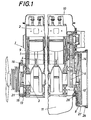
- Fig. 1 eine mehrzylindrige Hubkolben-Brennkraftmaschine im vertikalen Längsschnitt,
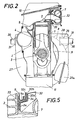
- Fig. 2 im vertikalen Querschnitt,
- Fig. 3 in Stirnansicht bei abgenommenem Lüfterrad,
- Fig. 4 den Antrieb des Lüfterrades und der Hilfseinrichtungen vergrößert im Axialschnitt und
- Fig. 5 die Befestigung des die Abgassammelleitung umschließenden Gehäuses als Detail ebenfalls im größeren Maßstab.
- 1 is a multi-cylinder reciprocating internal combustion engine in vertical longitudinal section,
- 2 in vertical cross section,
- 3 in front view with the fan wheel removed,
- Fig. 4 enlarged the drive of the fan wheel and the auxiliary devices in axial section and
- Fig. 5 shows the attachment of the housing surrounding the exhaust manifold as a detail also on a larger scale.
Die Zylinder 1, die Zylinderköpfe 2, die Kurbelwelle 3 samt dem von den Kurbelkröpfungen und den Pleueln 4 gebildeten Triebwerk, die Nockenwelle 5 mit den Steuerungsrädern 6 und die Ansaug- sowie Abgassammelleitung 7 bilden einen Triebwerksblock I, der kein eigenes Kurbelgehäuse aufweist, aber mit dem Schwungradgehäuse 8 zu einem Aggregat starr verbunden ist, an das sich ebenfalls in starrer Verbindung das nicht dargestellte Getriebe anschließen kann. Der Triebwerksblock wird allseits von einer Verschalung 9 umschlossen, die einen abnehmbaren Deckel 10 zum Zugänglichmachen der Ventilkipphebel u. dgl. sowie eine Ölwanne 11 besitzt und einen Ölraum bildet. Die Verschalung 9 ist über körperschallisolierende Dichtelemente 12, 13 am Triebwerksblock I befestigt, wobei die Dichtelemente 12, 13 an den Stirnseiten des Triebwerksblockes I angeordnet und ringförmig gestaltet sind.The
Das dem Schwungrad 14 abgekehrte Ende des gebildeten Aggregates ist an einem Querträger 15 unter Zwischenlage eines elastischen und körperschalldämmenden Ringes 16 aufgehängt, wobei an dem Querträger 15, der sich seinerseits an Längsträgern 17 eines Fahrgestelles abstützt, Hilfseinrichtungen, wie Lichtmaschine 18, Wasserpumpe 19 und Kompressor 20 (Fig. 3), befestigt sind. Gemäß Fig. 4 ist an dem Querträger 15 ein zur Kurbelwelle 3 koaxialer, zur Abdeckung dienender Lagerschild 21 angeschraubt, der mit einer Lagerung 22 für die Welle 23 der Antriebsriemenscheibe 24 für die Hilfseinrichtungen 18, 19, 20 versehen ist. Die Welle 23 ist mit der Kurbelwelle 3 über eine elastische, körperschallisolierende Kupplung 25 verbunden. Das Schwungradgehäuse 8 weist eine eigene, an ihm unter Zwischenlage körperschalldämmender Ringe 26 abgestützte Verschalung 27 auf, die mit ihrem Teil 27a auch den Anlasser umschließt. Ferner sind gemäß Fig. 2 im Schwungradgehäuse 8 Augen 28 vorgesehen, die eine Gummiausfütterung 29 aufweisen und zur Lagerung von Tragzapfen 30 für das gebildete Aggregat dienen. Die Verschalung 27 des Schwungradgehäuses 8 stützt sich an den Tragzapfen 30 ebenfalls über körperschalldämmende Ringe 31 ab.The end facing away from the
Die Verschalung 9 weist im Bereich der Abgassammelleitung 7 eine längliche Öffnung auf, die durch ein die Abgassammelleitung 7 umschließendes Gehäuse 32 verschlossen ist. Der Rand 9a der Öffnung der Verschalung 9 schmiegt sich unter Zwischenlage einer elastischen Dichtung 33 (siehe insbesondere Fig. 5) an das Gehäuse 32 an, das in diesem Randbereich der Öffnung aus durch wärmebeständige und körperschalldämmende Flachdichtungen 34 voneinander getrennten Schichten 32a, 32b, 32c besteht.The
Claims (6)
Applications Claiming Priority (2)
| Application Number | Priority Date | Filing Date | Title |
|---|---|---|---|
| AT1487/81 | 1981-03-31 | ||
| AT0148781A AT387624B (en) | 1981-03-31 | 1981-03-31 | PISTON PISTON ENGINE |
Publications (2)
| Publication Number | Publication Date |
|---|---|
| EP0062030A1 EP0062030A1 (en) | 1982-10-06 |
| EP0062030B1 true EP0062030B1 (en) | 1985-07-10 |
Family
ID=3514955
Family Applications (1)
| Application Number | Title | Priority Date | Filing Date |
|---|---|---|---|
| EP82890045A Expired EP0062030B1 (en) | 1981-03-31 | 1982-03-24 | Reciprocating piston internal-combustion engine |
Country Status (7)
| Country | Link |
|---|---|
| US (1) | US4480608A (en) |
| EP (1) | EP0062030B1 (en) |
| JP (1) | JPS57176345A (en) |
| AT (1) | AT387624B (en) |
| CA (1) | CA1189454A (en) |
| DE (1) | DE3264630D1 (en) |
| YU (1) | YU43512B (en) |
Families Citing this family (11)
| Publication number | Priority date | Publication date | Assignee | Title |
|---|---|---|---|---|
| DE3408011A1 (en) * | 1984-03-03 | 1985-09-05 | Klein, Schanzlin & Becker Ag, 6710 Frankenthal | SEALING FOR PARTIAL FLANGE AND SEALING HOUSING OF LONG-SIDED MACHINE HOUSINGS |
| US4669432A (en) * | 1986-05-16 | 1987-06-02 | Kabushiki Kaisha Komatsu Seisakusho | Sealing device for an oil pan adapter in an internal combustion engine |
| DE3668664D1 (en) * | 1986-07-10 | 1990-03-08 | Man Nutzfahrzeuge Ag | CAPSULE FOR DRIVE ENGINE IN MOTOR VEHICLES. |
| AT389744B (en) * | 1987-09-09 | 1990-01-25 | Steyr Daimler Puch Ag | SOUND-INSULATING PANELING FOR INTERNAL COMBUSTION ENGINES |
| AT392132B (en) * | 1987-11-03 | 1991-01-25 | Steyr Daimler Puch Ag | CONNECTION OF THE CRANKSHAFT OF A SOUND-ENCLOSED INTERNAL COMBUSTION ENGINE WITH THE COAXIAL DRIVE SHAFT OF THE AUXILIARIES OUTSIDE THE CAPSULE |
| ATA108690A (en) * | 1990-05-16 | 1994-12-15 | Laimboeck Franz | LIQUID-COOLED INTERNAL COMBUSTION ENGINE |
| US5665019A (en) * | 1996-02-05 | 1997-09-09 | Ford Global Technologies, Inc. | Chain guide mounting assembly for the reduction of chain induced noise and vibration in a chain driven overhead cam internal combustion engine |
| US6178939B1 (en) * | 1998-06-24 | 2001-01-30 | Siemens Canada Limited | Housing system |
| DE10358117A1 (en) * | 2003-12-12 | 2005-07-14 | Man Nutzfahrzeuge Ag | gasket |
| AT503764B1 (en) * | 2007-09-06 | 2009-01-15 | Avl List Gmbh | FLYWHEEL HOUSING |
| CN112682621B (en) * | 2020-12-21 | 2023-01-20 | 中国北方发动机研究所(天津) | Split type flywheel housing structure of integrated oil circuit |
Citations (2)
| Publication number | Priority date | Publication date | Assignee | Title |
|---|---|---|---|---|
| AT308475B (en) * | 1969-09-08 | 1973-07-10 | List Hans | Soundproof casing for internal combustion engines |
| DE2612182A1 (en) * | 1975-04-18 | 1976-10-28 | List Hans | QUIET COMBUSTION ENGINE |
Family Cites Families (13)
| Publication number | Priority date | Publication date | Assignee | Title |
|---|---|---|---|---|
| DE306982C (en) * | 1915-12-18 | |||
| US2875746A (en) * | 1956-05-09 | 1959-03-03 | Gen Motors Corp | Engine accessory support means |
| US3263663A (en) * | 1963-09-09 | 1966-08-02 | Crusader Marine Corp | Engine |
| AT278448B (en) * | 1967-08-21 | 1970-01-26 | H C Hans Dipl Ing Dr Dr List | Internal combustion engine with noise-absorbing casing |
| US3863936A (en) * | 1973-03-27 | 1975-02-04 | Farnam Co F D | High temperature gasket structure and method of producing same |
| GB1451707A (en) * | 1974-07-26 | 1976-10-06 | British Uralite Ltd | Noise control materials |
| JPS5516090Y2 (en) * | 1976-03-26 | 1980-04-15 | ||
| US4137888A (en) * | 1976-11-24 | 1979-02-06 | Allis-Chalmers Corporation | Sound abatement device for internal combustion engine |
| DE2804833A1 (en) * | 1977-02-24 | 1978-08-31 | List Hans | QUIET COMBUSTION ENGINE |
| DE2736378C2 (en) * | 1977-08-12 | 1985-12-19 | Klöckner-Humboldt-Deutz AG, 5000 Köln | Auxiliary machines for the air-cooled internal combustion engine of a tractor |
| AT365309B (en) * | 1977-08-18 | 1982-01-11 | List Hans | INTERNAL COMBUSTION ENGINE WITH SOUND-INSULATING PANELING |
| AT375444B (en) * | 1977-12-07 | 1984-08-10 | Steyr Daimler Puch Ag | PISTON PISTON ENGINE |
| AT374569B (en) * | 1979-02-07 | 1984-05-10 | List Hans | INTERNAL COMBUSTION ENGINE |
-
1981
- 1981-03-31 AT AT0148781A patent/AT387624B/en not_active IP Right Cessation
-
1982
- 1982-03-18 US US06/359,279 patent/US4480608A/en not_active Expired - Fee Related
- 1982-03-24 DE DE8282890045T patent/DE3264630D1/en not_active Expired
- 1982-03-24 EP EP82890045A patent/EP0062030B1/en not_active Expired
- 1982-03-30 CA CA000399768A patent/CA1189454A/en not_active Expired
- 1982-03-30 JP JP57050258A patent/JPS57176345A/en active Granted
- 1982-03-31 YU YU718/82A patent/YU43512B/en unknown
Patent Citations (2)
| Publication number | Priority date | Publication date | Assignee | Title |
|---|---|---|---|---|
| AT308475B (en) * | 1969-09-08 | 1973-07-10 | List Hans | Soundproof casing for internal combustion engines |
| DE2612182A1 (en) * | 1975-04-18 | 1976-10-28 | List Hans | QUIET COMBUSTION ENGINE |
Also Published As
| Publication number | Publication date |
|---|---|
| JPS6315471B2 (en) | 1988-04-05 |
| US4480608A (en) | 1984-11-06 |
| YU71882A (en) | 1985-03-20 |
| YU43512B (en) | 1989-08-31 |
| DE3264630D1 (en) | 1985-08-14 |
| CA1189454A (en) | 1985-06-25 |
| AT387624B (en) | 1989-02-27 |
| EP0062030A1 (en) | 1982-10-06 |
| JPS57176345A (en) | 1982-10-29 |
| ATA148781A (en) | 1988-07-15 |
Similar Documents
| Publication | Publication Date | Title |
|---|---|---|
| DE1775468C3 (en) | Internal combustion engine with noise-absorbing casing | |
| EP0062030B1 (en) | Reciprocating piston internal-combustion engine | |
| DE1914162C3 (en) | Air-cooled single cylinder internal combustion engine | |
| US3684053A (en) | Internal combustion engine with sound-absorbing casing | |
| DE1576775C3 (en) | Internal combustion engine with sound-insulating casing | |
| US3464398A (en) | Soundproofed internal combustion engine | |
| DE2612182A1 (en) | QUIET COMBUSTION ENGINE | |
| DE2922030A1 (en) | COMBUSTION MACHINE | |
| DE2920082C2 (en) | Internal combustion engine with structure-borne noise insulating element between the engine support and the crankcase | |
| US4213439A (en) | Internal combustion engine | |
| DE3050893C2 (en) | ||
| DE2065889A1 (en) | COMBUSTION MACHINE WITH SOUND-INSULATING CASING | |
| DE2801431A1 (en) | Piston engine fitter in outer trough - has centring damper rings at ends of cylinder block coaxial to crankshaft | |
| DE3831334C2 (en) | ||
| DE2920081A1 (en) | INTERNAL COMBUSTION ENGINE | |
| DE4041388C2 (en) | Internal combustion engine with acoustic hood | |
| EP0435847B1 (en) | Reciprocating internal combustion piston engine | |
| DE3016673A1 (en) | LOW-NOISE INTERNAL COMBUSTION ENGINE | |
| DE4141881C2 (en) | Silenced reciprocating internal combustion engine | |
| AT394758B (en) | INTERNAL COMBUSTION ENGINE | |
| EP0457750B1 (en) | Internal combustion engine with cooling liquid | |
| AT400742B (en) | Internal combustion engine with reciprocating pistons | |
| EP0252178B1 (en) | Shell for the drive engine in a motor vehicle | |
| AT399916B (en) | Internal combustion engine having a soundproofing cowling | |
| DE343626C (en) | Cylinder arrangement for internal combustion engines |
Legal Events
| Date | Code | Title | Description |
|---|---|---|---|
| PUAI | Public reference made under article 153(3) epc to a published international application that has entered the european phase |
Free format text: ORIGINAL CODE: 0009012 |
|
| AK | Designated contracting states |
Designated state(s): DE FR GB IT NL SE |
|
| 17P | Request for examination filed |
Effective date: 19821016 |
|
| ITF | It: translation for a ep patent filed |
Owner name: MODIANO & ASSOCIATI S.R.L. |
|
| GRAA | (expected) grant |
Free format text: ORIGINAL CODE: 0009210 |
|
| AK | Designated contracting states |
Designated state(s): DE FR GB IT NL SE |
|
| REF | Corresponds to: |
Ref document number: 3264630 Country of ref document: DE Date of ref document: 19850814 |
|
| ET | Fr: translation filed | ||
| PLBE | No opposition filed within time limit |
Free format text: ORIGINAL CODE: 0009261 |
|
| STAA | Information on the status of an ep patent application or granted ep patent |
Free format text: STATUS: NO OPPOSITION FILED WITHIN TIME LIMIT |
|
| 26N | No opposition filed | ||
| ITTA | It: last paid annual fee | ||
| PGFP | Annual fee paid to national office [announced via postgrant information from national office to epo] |
Ref country code: GB Payment date: 19940215 Year of fee payment: 13 |
|
| PGFP | Annual fee paid to national office [announced via postgrant information from national office to epo] |
Ref country code: FR Payment date: 19940218 Year of fee payment: 13 |
|
| PGFP | Annual fee paid to national office [announced via postgrant information from national office to epo] |
Ref country code: SE Payment date: 19940223 Year of fee payment: 13 |
|
| PGFP | Annual fee paid to national office [announced via postgrant information from national office to epo] |
Ref country code: NL Payment date: 19940331 Year of fee payment: 13 |
|
| EAL | Se: european patent in force in sweden |
Ref document number: 82890045.6 |
|
| PG25 | Lapsed in a contracting state [announced via postgrant information from national office to epo] |
Ref country code: GB Effective date: 19950324 |
|
| PG25 | Lapsed in a contracting state [announced via postgrant information from national office to epo] |
Ref country code: SE Effective date: 19950325 |
|
| PG25 | Lapsed in a contracting state [announced via postgrant information from national office to epo] |
Ref country code: NL Effective date: 19951001 |
|
| GBPC | Gb: european patent ceased through non-payment of renewal fee |
Effective date: 19950324 |
|
| PG25 | Lapsed in a contracting state [announced via postgrant information from national office to epo] |
Ref country code: FR Free format text: LAPSE BECAUSE OF NON-PAYMENT OF DUE FEES Effective date: 19951130 |
|
| NLV4 | Nl: lapsed or anulled due to non-payment of the annual fee |
Effective date: 19951001 |
|
| EUG | Se: european patent has lapsed |
Ref document number: 82890045.6 |
|
| REG | Reference to a national code |
Ref country code: FR Ref legal event code: ST |
|
| PGFP | Annual fee paid to national office [announced via postgrant information from national office to epo] |
Ref country code: DE Payment date: 20010313 Year of fee payment: 20 |