EP0252178B1 - Shell for the drive engine in a motor vehicle - Google Patents
Shell for the drive engine in a motor vehicle Download PDFInfo
- Publication number
- EP0252178B1 EP0252178B1 EP86109435A EP86109435A EP0252178B1 EP 0252178 B1 EP0252178 B1 EP 0252178B1 EP 86109435 A EP86109435 A EP 86109435A EP 86109435 A EP86109435 A EP 86109435A EP 0252178 B1 EP0252178 B1 EP 0252178B1
- Authority
- EP
- European Patent Office
- Prior art keywords
- engine
- basic
- casing
- casing member
- air
- Prior art date
- Legal status (The legal status is an assumption and is not a legal conclusion. Google has not performed a legal analysis and makes no representation as to the accuracy of the status listed.)
- Expired - Lifetime
Links
Images


Classifications
-
- F—MECHANICAL ENGINEERING; LIGHTING; HEATING; WEAPONS; BLASTING
- F02—COMBUSTION ENGINES; HOT-GAS OR COMBUSTION-PRODUCT ENGINE PLANTS
- F02B—INTERNAL-COMBUSTION PISTON ENGINES; COMBUSTION ENGINES IN GENERAL
- F02B77/00—Component parts, details or accessories, not otherwise provided for
- F02B77/11—Thermal or acoustic insulation
- F02B77/13—Acoustic insulation
Definitions
- the invention relates to a device for soundproofing a drive motor in a motor vehicle, in particular a commercial vehicle, by means of a capsule enclosing it at a short distance.
- the cooling flow of a cooling fan is to be guided through the capsule.
- Such a passage of cooling air through a closed muffler capsule has the purpose of cooling the additional motor assemblies arranged within the muffler capsule in order to keep the temperature increase caused by the capsule or the engine's own heat development that cannot be dissipated within reasonable limits.
- a disadvantage of carrying the cooling air of a cooling fan through the capsule is that the cooling air inlet and outlet openings have to be made relatively large, in particular in the case of larger motors, and are therefore very difficult to protect against the escape of sound from the capsule.
- a very significant disadvantage of the capsule described in the publication is that the auxiliary units are difficult to access for maintenance and repair purposes, even when closable openings are provided.
- a device for sound damping of motors described at the outset is also known from DT-PS 306 982.
- this document does not deal with the problem of heat balance in the case of encapsulated motors and also gives no indication of how auxiliary units of the encapsulated motors can be protected against overheating.
- a device for soundproofing an internal combustion engine in a motor vehicle by means of a capsule enclosing it at a short distance according to US Pat. No. 4,137,888 is known.
- the capsule is self-supporting and multi-part and consists of a capsule body, an upper cover and an oil pan cladding. With the exception of the injection pump, all auxiliary units are outside the casing.
- the invention has for its object to provide a generic sound damping device that has a high degree of damping, which is designed to save space and weight, good accessibility to the drive motor and the associated units for maintenance and repair work and at the same time allows operating temperatures of the drive motor and to keep the other drive and auxiliary units low despite the soundproofing.
- auxiliary units from the group of the following auxiliary units - air compressor, alternator, hydraulic motor for steering aid, exhaust gas turbocharger, manual transmission, V-belts and V-belt pulleys from water pump, alternator and fan, torsion damper, tensioning rollers, water thermostat, water pump, viscous coupling for Fans, water hoses, hose connections, fuel feed pump, fuel filter - at least partially or partially have connection capsules, which are either connected directly to the basic motor (3), to the auxiliary units or to the basic capsule body (2) and that the interior of the capsule (1) is sound-absorbing Routes containing material are subjected to such a small amount of purge air, which just effectively prevents an explosion hazard due to the accumulation of gases.
- the capsule Since the capsule is arranged relatively close to the motor contour due to the exclusion of the auxiliary units, the sound damping begins immediately where the sound is generated, so that only a small area is illuminated by the main noise source.
- the exclusion of the auxiliary units has the further considerable advantage that only a small amount of air is used, which is not defined as cooling air but as purge air. In this way, a correspondingly large cooling fan is not required, since the small amount of purge air is only used for this, e.g. to effectively counter an explosion hazard due to the accumulation of gases.
- An essential advantage of the device according to the invention is that it is easy to maintain, repair and install; the capsule division optimally takes into account the band production by integrating the cubic, self-supporting capsule base body as an assembly part in the band production.
- the intervention options remain almost the same as for the unenclosed motor.
- the upper cover By removing the upper cover, the following can be replaced: valve cover, cylinder heads, injector holder, screw connections of the injection lines, exhaust manifold and all corresponding seals.
- the oil pan cover is also removed, the following can also be replaced: oil pan, pistons, connecting rods, cylinder liners, connecting rod bearings, crankshaft bearings and all corresponding seals and the like.
- the capsule body belongs to the engine and only needs if the crankcase is defective, e.g.
- the capsule is a self-supporting structure provided with openings for the auxiliary units and should therefore not be understood as a series of facing shells. Since the soundproofing of an internal combustion engine is a very complex process, the measures described above must be supplemented by further, mainly additional encapsulations and primary soundproofing.
- the effect of the purge air can be enhanced by air movement inside the capsule as a result of thermal effects and by the air flowing out of the radiator fan.
- Sol The capsule is then ventilated with a small amount of purge air to avoid the accumulation of flammable gases. Cooling air is not required because the heat-generating accessories are outside the capsule and the engine itself is water-cooled.
- a partitioned space is provided around the exhaust manifold with corresponding supply and exhaust air openings, the partitioned space being provided by an additional capsule which is integral with the capsule base body and half with the upper cover, and with an additional capsule encompassing the exhaust manifold inlet Partition is formed.
- the air heated at the exhaust manifold is directed upwards, so that cold air (approx. 330 K) can be drawn in from the capsule and the air movement inside the capsule is supported.
- a quasi "divided room” is formed around the exhaust manifold with corresponding supply and exhaust air openings.
- Cooling in the area mentioned also makes sense because partial overheating is avoided and the use of particularly expensive materials (seals and high-quality alloys for exhaust manifolds and screws) is eliminated. Coking of the engine oil on the inside of the valve covers and heating of the cylinder head are also avoided.
- these encompassing and shielding front shells are arranged on the oil filter head and on the charging group of the exhaust gas turbine.
- the above-described auxiliary units whose airborne sound radiation is measurably involved in the overall noise level, are shielded by absorbing front shells.
- the storage of the facing shells is decoupled from structure-borne noise on the internal combustion engine or on the auxiliary unit itself.
- the absorbing facing shells do not need to lie close to the capsule, but can be arranged at a distance from the capsule and the aggregate, so that assembly and maintenance are not impaired.
- a torsion damper consisting of a primary part and a secondary part having a rubber part, with shells being provided on both sides of the end faces of the torsion damper, one of which directly and the other via Connection plates, which are arranged within the V-belt guide, are connected to the outer wall of the capsule base body.
- V-belt pulleys e.g. B. for water pump and alternator to decouple structure-borne noise
- the V-belt pulleys consist of primary and secondary parts, which are connected on the end face via several elastomer rings or the like and have a small annular space filled with viscose liquid on the inside. Pressed V-belt pulleys made of sheet metal, as are often used in diesel engines, are unsuitable for engines with capsules. V-belt pulleys must either have much more mass or, as the invention shows, there must be structure-borne noise decoupling. Additional damping is achieved by introducing viscose liquid between the hub parts.
- the vibrating metals connecting the capsule base body to the base motor are arranged on the outside of the capsule base body. In this way, they are visible, measurable and interchangeable without having to disassemble the capsule. They are also advantageously not influenced by the temperature prevailing in the capsule, which increases their resistance to aging.
- the exhaust pipe is structure-borne soundproofed, an outer pipe being arranged at a distance from the inner exhaust pipe and the space being made with an elastic fabric, e.g. B. asbestos substitute or filled with air, or it is the exhaust pipe in a certain, depending on the radiated frequency spectrum surrounded by a pipe silencer.
- an elastic fabric e.g. B. asbestos substitute or filled with air
- the acoustic weak points here are the inner compensators, as well as reinforced hoses, even in heavy versions.
- the cavity between the motor and the capsule is filled with absorption material.
- the space between the capsule and the motor describes a diffuse reverberation space.
- Absorption material is installed to reduce the reverberation effect and thus increase the capsule effect.
- the points of absorption are not so significant.
- the percentage of the absorption area in the total area is more important. Damping pads are applied to strongly vibrating capsule surfaces beforehand.
- the invention is illustrated in a large number of exemplary embodiments.
- FIG. 1 and 2 show an internal combustion engine (3) with a complete capsule (1), which consists of a capsule base body (2), an upper cover (4) and an oil pan lining (5).
- the individual capsule components are preferably connected to one another via commercially available quick fasteners.
- a serious feature of this capsule arrangement is that all of the auxiliary units that are not absolutely necessary for a test run are located outside the capsule and additional measures have been taken to reduce their noise component in the overall noise level. In this way there is no cooling of the heat-radiating auxiliary units which, if they were arranged in the capsule, would require a cooling air flow and thus an additional large-volume cooler. However, it is sufficient to branch off a very small amount of purge air from the radiator fan so that no flammable gases can form inside the capsule.
- Fig. 3 shows the connection of the capsule body (2) to the motor housing (8), namely by means of vibrating metal elements (6, 7), which are attached to the outside of the capsule, so that each one can be replaced without disassembling the capsule itself.
- Fig. 4 shows the encapsulation of the exhaust manifold (9) by means of a capsule part (11), which is assigned in one piece to the capsule body (2) and the other half in one piece to the upper cover (4).
- a partition (12) By arranging a partition (12) on the engine-facing part of the exhaust manifold, enclosing the same, a partitioned space (10) is created, whereby the air heated at the exhaust manifold is directed upwards and cold air (approx. 330 K) is drawn in from the lower capsule area .
- the cutting disc (12) consists of a sheet with an insulating layer (14) and a steel sheet (13) attached to it, on which a further steel sheet (15) is arranged at a distance.
- Fig. 5 shows an oil filter head (16) with a spaced absorbent facing (17). This arrangement allows easy access to the oil filter at any time to perform maintenance or cleaning tasks on it.
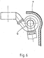
- Fig. 6 shows the charging group (18), (gas turbine + compressor) with a noise-absorbing front shell (19) arranged at a distance from it.
- Fig. 7 shows a torsion damper (23) and Fig. 8 shows the arrangement of this torsion damper in a front view.
- the primary part (20) of the torsion damper (23) attached to the crankshaft is connected via a rubber part (22) to a secondary part (21) containing the V-belt grooves.
- Front shells (24, 25) are arranged on the front side of the torsion damper (23), the front shell (24) being attached directly and the front shell (25) via connecting plates (26) on the outer wall of the capsule base body.
- the size of the facing shells corresponds to the diameter of the torsion damper (23).
- the connecting plates (26) lie within the V-belt guide (27) of the torsion damper (23), alternator V-belt pulley (28) and water pump V-belt pulley (29).
- the facing shells (24, 25) can also be firmly connected to the torsion damper (23).
- the V-belt pulleys (28, 29) consist of a primary part (30) and a secondary part (31). These are connected to one another at the end face via elastomer rings (32, 33). On the inside there is an annular space (33) between the parts (30) and (31), which is filled with viscose material.
- FIGS. 10 and 11 show structure-borne noise-insulated exhaust pipes (34).
- the exhaust pipes between the manifold and the muffler in conventional design already emit considerable airborne noise caused by structure-borne noise.
- an outer pipe (35) is arranged at a distance from the exhaust pipe (34), the intermediate space (36) being filled with an elastic intermediate layer (36) (e.g. asbestos substitute) or air.
- the exhaust pipe (34) is surrounded by a silencer (37), which consists of a perforated plate (39), absorption material (40) and an outer pipe (41) arranged at a distance from it.
- Fig. 12 shows an intake pipe (42) with surface silencer (46).
- the suction line (42) is composed of a partial section (43) and a partial section (44) which are connected by an inner compensator (45).
- the internal compensator is completely sufficient for an unenclosed motor, but not for an encapsulated one.
- the external expansion joints (47, 48), which are arranged at the end and are connected to the silencer (46), are used here.
- the surface silencer (46) with external expansion joints (47, 48) is preferably used if a short overall length is required and / or very high pulsations and vibrations are present.
- Openings here not provided with reference numerals that are important for maintenance work, such as. B. oil filler neck, nozzle for oil level control and oil drain are led out of the capsule.
- the space between capsule (1) and motor (3) describes a diffuse reverberation space; To reduce the reverberation effect and thus increase the capsule effect, absorption material is installed.
- the locations of the absorption are not so significant; what is more important is the percentage of the absorption area in the total area, the thickness of the absorption material being limited by the space between the capsule and the motor.
Abstract
Description
Die Erfindung bezieht sich auf eine Vorrichtung zur Schalldämpfung eines Antriebsmotors in einem Kraftfahrzeug, insbesondere Nutzfahrzeug, mittels einer diesen mit geringem Abstand umschließenden Kapsel.The invention relates to a device for soundproofing a drive motor in a motor vehicle, in particular a commercial vehicle, by means of a capsule enclosing it at a short distance.
Um die Geräuschbelästigung von mit Verbrennungsmotoren angetriebenen Fahrzeugen nach außen hin zu vermindern, ist man dazu übergegangen, die Verbrennungsmotoren einzukapseln. Eine solche Vorrichtung zum schalldämpfenden Einbau eines Verbrennungsmotors wird in der automobiltechnischen Zeitschrift ATZ, 1972, Seite 267, offenbart.In order to reduce the noise pollution from vehicles driven by internal combustion engines to the outside, it has gone over to encapsulating the internal combustion engines. Such a device for sound-absorbing installation of an internal combustion engine is disclosed in the automotive engineering magazine ATZ, 1972, page 267.
Bei der in dieser Druckschrift offenbarten Ausführung einer schalldämmenden Verkleidung eines Verbrennungsmotors soll jedoch der Kühlstrom eines Kühlgebläses durch die Kapsel geführt werden. Eine solche Durchführung von Kühlluft durch eine geschlossene Schalldämpfkapsel hat den Zweck, die innerhalb der Schalldämpfkapsel angeordneten zusätzlichen Motoraggregate zu kühlen, um die durch die Kapsel bedingte Temperaturerhöhung bzw. nicht abführbare eigene Wärmeentwicklung des Motors in vertretbaren Grenzen zu halten. Ein Nachteil der Durchführung der Kühlluft eines Kühlgebläses durch die Kapsel besteht darin, daß insbesondere bei größeren Motoren die Kühlluft-Eintritts- und Austrittsöffnungen verhältnismäßig groß ausgeführt sein müssen und dadurch nur sehr schwer gegen den Austritt von Schall aus der Kapsel geschützt werden können.In the embodiment of a sound-absorbing casing of an internal combustion engine disclosed in this publication, however, the cooling flow of a cooling fan is to be guided through the capsule. Such a passage of cooling air through a closed muffler capsule has the purpose of cooling the additional motor assemblies arranged within the muffler capsule in order to keep the temperature increase caused by the capsule or the engine's own heat development that cannot be dissipated within reasonable limits. A disadvantage of carrying the cooling air of a cooling fan through the capsule is that the cooling air inlet and outlet openings have to be made relatively large, in particular in the case of larger motors, and are therefore very difficult to protect against the escape of sound from the capsule.
Ein ganz erheblicher Nachteil der in der Druckschrift beschriebenen Kapsel besteht weiterhin darin, daß die Nebenaggregate zu Wartungs- und Reparaturzwecken schwer zugänglich sind, auch dann, wenn verschließbare Offnungen vorgesehen sind.A very significant disadvantage of the capsule described in the publication is that the auxiliary units are difficult to access for maintenance and repair purposes, even when closable openings are provided.
Eine eingangs beschriebene Vorrichtung zur Schalldämpfung von Motoren ist auch aus der DT-PS 306 982 bekannt. Diese Druckschrift beschäftigt sich jedoch nicht mit dem Problem des Wärmehaushalts bei gekapselten Motoren und ergibt auch keinen Hinweis darauf, wie Nebenaggregate der gekapselten Motoren vor Überhitzung geschützt werden können.A device for sound damping of motors described at the outset is also known from DT-PS 306 982. However, this document does not deal with the problem of heat balance in the case of encapsulated motors and also gives no indication of how auxiliary units of the encapsulated motors can be protected against overheating.
Es ist eine Vorrichtung zur Schalldämpfung eines Verbrennungsmotors in einem Kraftfahrzeug mittels einer diesen mit geringem Abstand umschließenden Kapsel nach der US-A 4 137 888 bekannt. Die Kapsel ist selbsttragend und mehrteilig ausgebildet und besteht aus einem Kapsel-Grundkörper, einem oberen Deckel und einer Ölwannenverkleidung. Alle Nebenaggregate befinden sich bis auf die Einspritzpumpe ungekapselt außerhalb der Verkleidung.A device for soundproofing an internal combustion engine in a motor vehicle by means of a capsule enclosing it at a short distance according to US Pat. No. 4,137,888 is known. The capsule is self-supporting and multi-part and consists of a capsule body, an upper cover and an oil pan cladding. With the exception of the injection pump, all auxiliary units are outside the casing.
Der Erfindung liegt die Aufgabe zugrunde, eine gattungsgemäße Schalldämpfvorrichtung zu schaffen, die einen hohen Dämpfungsgrad aufweist, die raum- und gewichtssparend gestaltet ist, eine gute Zugänglichkeit zum Antriebsmotor und den zugehörigen Aggregaten für Wartungs- und Reparaturarbeiten ermöglicht und gleichzeitig gestattet, Betriebstemperaturen des Antriebsmotors und der weiteren Antriebs- und Zusatzaggregate trotz der Schalldämpfung niedrig zu halten.The invention has for its object to provide a generic sound damping device that has a high degree of damping, which is designed to save space and weight, good accessibility to the drive motor and the associated units for maintenance and repair work and at the same time allows operating temperatures of the drive motor and to keep the other drive and auxiliary units low despite the soundproofing.
Dies wird erfindungsgemäß dadurch erreicht, daß mehrere Nebenaggregate aus der Gruppe der folgenden Nebenaggregate - Luftpresser, Lichtmaschine, Hydromotor für Lenkhilfe, Abgasturbolader, Schaltgetriebe, Keilriemen und Keilriemenscheiben von Wasserpumpe, Lichtmaschine und Lüfter, Torsionsdämpfer, Spannrollen, Wasserthermostat, Wasserpumpe, Viskose-Kupplung für Lüfter, Wasserschläuche, Schlauchverbindungen, Treibstoffförderpumpe, Treibstoffilter - zumindest teilweise oder bereichsweise Anschlußkapseln aufweisen, die entweder direkt mit dem Grundmotor (3), mit den Nebenaggregaten oder mit dem Kapsel-Grundkörper (2) verbunden sind und daß das Kapselinnere (1) über schallabsorbierendes Material aufweisende Strecken mit einer derartig geringen Menge Spülluft beaufschlagt ist, die eine Explosionsgefahr infolge Ansammlung von Gasen gerade wirksam verhindert. Indem die Kapsel durch Ausschluß der Nebenaggregate verhältnismäßig eng zur Motorkontur angeordnet ist, beginnt die Schalldämpfung schon unmittelbar dort, wo der Schall entsteht, so daß nur eine kleine Fläche von der Hauptgeräuschquelle angestrahlt wird. Der Ausschluß der Nebenaggregate hat als weiteren erheblichen Vorteil zur Folge, daß nur eine geringe Menge Luft, die nicht als Kühlluft sondern als Spülluft definiert wird, gebraucht wird. Solcherart entfällt ein entsprechend großes Kühlgebläse, dient die geringe Menge Spülluft doch nur dazu, z.B. einer Explosionsgefahr infolge Ansammlung von Gasen wirksam zu begegnen. Ein wesentlicher Vorzug der erfindungsgemäßen Vorrichtung besteht in der Wartungs-, Reparatur- und Montagefreundlichkeit; so berücksichtigt die Kapselteilung in optimaler Weise die Bandfertigung, indem der kubische, selbsttragende Kapsel-Grundkörper als Montageteil in die Bandfertigung integriert ist. Die Eingriffsmöglichkeiten bleiben nahezu wie beim ungekapselten Motor erhalten. Durch Entfernen des oberen Deckels können ausgewechselt werden: Ventilhaube, Zylinderköpfe, Einspritzdüsenhalter, Verschraubungen der Einspritzleitungen, Abgaskrümmer sowie alle entsprechenden Dichtungen. Wird noch die Ölwannenverkleidung abgebaut, so können zusätzlich ausgewechselt werden: Ölwanne, Kolben, Pleuel, Zylinderbuchsen, Pleuellager, Kurbelwellenlager sowie alle entsprechenden Dichtungen und ähnliches. Der Kapsel-Grundkörper ist dem Motor zugehörig und braucht nur bei Defekt des Kurbelgehäuses, z.B. durch Frostschäden, abgebaut werden. Die Kapsel ist ein selbsttragendes, mit Durchbrüchen für die Nebenaggregate versehenes Gebilde und darf somit nicht als eine Aneinanderreihung von Vorsatzschalen verstanden werden. Da die Schalldämpfung eines Verbrennungsmotors ein sehr komplexes Geschehen ist, müssen die vorbeschriebenen Maßnahmen durch weitere, hauptsächlich Zusatzkapselungen und primäre Schalldämpfungen, ergänzt werden.This is achieved according to the invention in that several auxiliary units from the group of the following auxiliary units - air compressor, alternator, hydraulic motor for steering aid, exhaust gas turbocharger, manual transmission, V-belts and V-belt pulleys from water pump, alternator and fan, torsion damper, tensioning rollers, water thermostat, water pump, viscous coupling for Fans, water hoses, hose connections, fuel feed pump, fuel filter - at least partially or partially have connection capsules, which are either connected directly to the basic motor (3), to the auxiliary units or to the basic capsule body (2) and that the interior of the capsule (1) is sound-absorbing Routes containing material are subjected to such a small amount of purge air, which just effectively prevents an explosion hazard due to the accumulation of gases. Since the capsule is arranged relatively close to the motor contour due to the exclusion of the auxiliary units, the sound damping begins immediately where the sound is generated, so that only a small area is illuminated by the main noise source. The exclusion of the auxiliary units has the further considerable advantage that only a small amount of air is used, which is not defined as cooling air but as purge air. In this way, a correspondingly large cooling fan is not required, since the small amount of purge air is only used for this, e.g. to effectively counter an explosion hazard due to the accumulation of gases. An essential advantage of the device according to the invention is that it is easy to maintain, repair and install; the capsule division optimally takes into account the band production by integrating the cubic, self-supporting capsule base body as an assembly part in the band production. The intervention options remain almost the same as for the unenclosed motor. By removing the upper cover, the following can be replaced: valve cover, cylinder heads, injector holder, screw connections of the injection lines, exhaust manifold and all corresponding seals. If the oil pan cover is also removed, the following can also be replaced: oil pan, pistons, connecting rods, cylinder liners, connecting rod bearings, crankshaft bearings and all corresponding seals and the like. The capsule body belongs to the engine and only needs if the crankcase is defective, e.g. due to frost damage. The capsule is a self-supporting structure provided with openings for the auxiliary units and should therefore not be understood as a series of facing shells. Since the soundproofing of an internal combustion engine is a very complex process, the measures described above must be supplemented by further, mainly additional encapsulations and primary soundproofing.
Nach einem ergänzenden Merkmal der Erfindung ist die Wirkung der Spülluft durch kapselinnere Luftbewegung infolge von Thermik und durch die abströmende Luft des Kühlerlüfters verstärkbar. Solcherart wird die Kapsel mit einer geringen Menge Spülluft zum Vermeiden einer Ansammlung von entzündlichen Gasen gelüftet. Kühlluft wird nicht benötigt, da sich die wärmeerzeugenden Nebenaggregate außerhalb der Kapsel befinden und der Motor selbst wassergekühlt ist.According to a supplementary feature of the invention, the effect of the purge air can be enhanced by air movement inside the capsule as a result of thermal effects and by the air flowing out of the radiator fan. Sol The capsule is then ventilated with a small amount of purge air to avoid the accumulation of flammable gases. Cooling air is not required because the heat-generating accessories are outside the capsule and the engine itself is water-cooled.
In weiterer Ausbildung der-Erfindung ist um den Abgaskrümmer ein abgeteilter Raum mit entsprechenden Zu- und Abluftöffnungen vorgesehen, wobei der abgeteilte Raum durch eine zu einer Hälfte dem Kapsel-Grundkörper und zur anderen Hälfte dem oberen Deckel einstückig zugehörigen Zusatzkapsel und durch eine den Abgaskrümmereingang umgreifende Trennwand gebildet ist. Auf diese Weise wird die am Abgaskrümmer erhitzte Luft gezielt aufwärts geführt, so daß Kaltluft (ca. 330 K) aus der Kapsel nachgesogen werden kann und die kapselinnere Luftbewegung unterstützt wird. Es wird ein quasi "geteilter Raum" mit entsprechenden Zu-und Abluftöffnungen um den Abgaskrümmer gebildet. Die Kühlung im genannten Bereich ist auch deshalb sinnvoll, weil partielle Überhitzungen vermieden werden und damit der Einsatz besonders teuerer Materialien (Dichtungen und hochwertige Legierungen für Abgaskrümmer und Schrauben) entfällt. Auch wird ein Verkoken des Motoröls auf der Innenseite der Ventilhauben und ein Aufheizen des Zylinderkopfes vermieden.In a further embodiment of the invention, a partitioned space is provided around the exhaust manifold with corresponding supply and exhaust air openings, the partitioned space being provided by an additional capsule which is integral with the capsule base body and half with the upper cover, and with an additional capsule encompassing the exhaust manifold inlet Partition is formed. In this way, the air heated at the exhaust manifold is directed upwards, so that cold air (approx. 330 K) can be drawn in from the capsule and the air movement inside the capsule is supported. A quasi "divided room" is formed around the exhaust manifold with corresponding supply and exhaust air openings. Cooling in the area mentioned also makes sense because partial overheating is avoided and the use of particularly expensive materials (seals and high-quality alloys for exhaust manifolds and screws) is eliminated. Coking of the engine oil on the inside of the valve covers and heating of the cylinder head are also avoided.
Nach weiteren Merkmalen sind am Ölfilterkopf und an der Ladegruppe der Abgasturbine diese umgreifende und abschirmende Vorsatzschalen angeordnet. Solcherart werden die vorbeschriebenen Nebenaggregate, deren Luftschallabstrahlung am gesamten Geräuschpegel meßbar beteiligt ist, durch absorbierende Vorsatzschalen abgeschirmt. Die Lagerung der Vorsatzschalen erfolgt Körperschallentkoppelt am Verbrennungsmotor oder am Nebenaggregat selbst. Die absorbierenden Vorsatzschalen brauchen nicht dicht an der Kapsel anliegen, vielmehr können sie im Abstand zur Kapsel und zum Aggregat angeordnet sein, so daß Montage und Wartung nicht beeinträchtigt sind.According to further features, these encompassing and shielding front shells are arranged on the oil filter head and on the charging group of the exhaust gas turbine. In this way, the above-described auxiliary units, whose airborne sound radiation is measurably involved in the overall noise level, are shielded by absorbing front shells. The storage of the facing shells is decoupled from structure-borne noise on the internal combustion engine or on the auxiliary unit itself. The absorbing facing shells do not need to lie close to the capsule, but can be arranged at a distance from the capsule and the aggregate, so that assembly and maintenance are not impaired.
Nach einem weiteren vorteilhaften Merkmal der Erfindung ist an einem aus einem Primär- und einem ein Gummiteil aufweisenden Sekundärteil bestehenden Torsionsdämpfer eine Zusatzdämpfung gegen den aus axialähnlichen Schwingungen resultierenden Lärm angebracht, wobei beiderseits der Stirnflächen des Torsionsdämpfers Vorsatzschalen vorgesehen sind, deren eine direkt und deren andere über Verbindungsbleche, die innerhalb der Keilriemenführung angeordnet sind, mit der Außenwand des Kapsel-Grundkörpers verbunden sind. Manche rotierenden, aus der Kapsel herausgeführten Teile lassen sich aufgrund ihrer Funktion nicht genügend vom Körperschall des Motors abkoppeln, so auch der Torsionsdämpfer im vorderen Kurbelwellen-Ende. Dieser führt torsionale und axiale Schwingungen aus. Die torsionalen Schwingungen werden durch die zwischen Primär- und Sekundärteil angeordnete Gummischicht eliminiert. Da das Primärteil an der Kurbelwelle fest angeschraubt ist, ist eine Dämpfung mittels Primärmaßnahmen nicht möglich, so daß die erfindungsgemäßen Vorsatzschalen Anwendung finden. Diese könnnen auch mit-rotierend direkt an den Stirnseiten des Torsionsdämpfers angebracht sein.According to a further advantageous feature of the invention, additional damping against the noise resulting from axially similar vibrations is attached to a torsion damper consisting of a primary part and a secondary part having a rubber part, with shells being provided on both sides of the end faces of the torsion damper, one of which directly and the other via Connection plates, which are arranged within the V-belt guide, are connected to the outer wall of the capsule base body. Some rotating parts that come out of the capsule cannot be uncoupled sufficiently from the structure-borne noise of the engine due to their function, including the torsion damper in the front end of the crankshaft. This carries out torsional and axial vibrations. The torsional vibrations are eliminated by the rubber layer arranged between the primary and secondary part. Since the primary part is firmly screwed onto the crankshaft, damping by means of primary measures is not possible, so that the facing shells according to the invention are used. These can also be attached to the end faces of the torsion damper in a rotating manner.
Vorteilhaft ist es auch, die verschiedenen Keilriemenscheiben, z. B. für Wasserpumpe und Lichtmaschine, Körperschall zu entkoppeln, wobei die Keilriemenscheiben aus Primär- und Sekundärteilen bestehen, die stirnseitig über mehrere Elastomerringe oder ähnlichem miteinander verbunden sind und innenseitig einen kleinen mit Viskoseflüssigkeit gefüllten Ringraum aufweisen. Gedrückte Keilriemenscheiben aus Blech, wie sie bei Dieselmotoren häufig verwendet werden, sind ungeeignet für Motoren mit Kapsel. Keilriemenscheiben müssen entweder viel mehr Masse aufweisen oder es muß, wie es die Erfindung zeigt, eine Körperschallentkopplung vorhanden sein. Eine zusätzliche Dämpfung erreicht man durch das Einbringen von Viskose-Flüssigkeit zwischen den Nabenteilen.It is also advantageous to use the various V-belt pulleys, e.g. B. for water pump and alternator to decouple structure-borne noise, the V-belt pulleys consist of primary and secondary parts, which are connected on the end face via several elastomer rings or the like and have a small annular space filled with viscose liquid on the inside. Pressed V-belt pulleys made of sheet metal, as are often used in diesel engines, are unsuitable for engines with capsules. V-belt pulleys must either have much more mass or, as the invention shows, there must be structure-borne noise decoupling. Additional damping is achieved by introducing viscose liquid between the hub parts.
Nach einem weiteren Merkmal der Erfindung sind in die den Kapsel-Grundkörper mit dem Grundmotor verbindenden Schwingmetalle außenseitig des Kapsel-Grundkörpers angeordnet. Auf diese Weise sind sie sichtbar, meßbar und auswechselbar, ohne das die Kapsel demontiert werden muß. Sie werden auch vorteilhafterweise nicht von der in der Kapsel herrschenden Temperatur beeinflußt, was ihre Alterungsbeständigkeit erhöht.According to a further feature of the invention, the vibrating metals connecting the capsule base body to the base motor are arranged on the outside of the capsule base body. In this way, they are visible, measurable and interchangeable without having to disassemble the capsule. They are also advantageously not influenced by the temperature prevailing in the capsule, which increases their resistance to aging.
Nach anderen Merkmalen der Erfindung ist das Abgasrohr köperschallisoliert ausgebildet, wobei zum inneren Abgasrohr ein Außenrohr im Abstand angeordnet ist und der Zwischenraum mit einem elastischen Gewebe, z. B. Asbestersatz oder mit Luft ausgefüllt ist, oder es ist das Abgasrohr in einem bestimmten, vom abgestrahlten Frequenzspektrum abhängigen Abstand von einem Rohr-Schalldämpfer umgeben. In der Ansaugleitung sind starke Pulsationen, die Schwingungen und Oberschwingungen hervorrufen, vorhanden. Die akustischen Schwachstellen sind hierbei die inneren Kompensatoren, sowie armierte Schläuche, auch in schwerer Ausführung.According to other features of the invention, the exhaust pipe is structure-borne soundproofed, an outer pipe being arranged at a distance from the inner exhaust pipe and the space being made with an elastic fabric, e.g. B. asbestos substitute or filled with air, or it is the exhaust pipe in a certain, depending on the radiated frequency spectrum surrounded by a pipe silencer. There are strong pulsations in the suction line, which cause vibrations and harmonics. The acoustic weak points here are the inner compensators, as well as reinforced hoses, even in heavy versions.
In besonders vorteilhafter Ausgestaltung der Erfindung ist der Hohlraum zwischen Motor und Kapsel mit Absorptionsmaterial ausgefüllt. Der Raum zwischen Kapsel und Motor beschreibt einen diffusen Hallraum. Um den Hallraumeffekt zu verringern und damit die Kapselwirkung zu erhöhen, wird Absorptionsmaterial eingebaut. Dabei sind die Stellen der Absorption nicht so erheblich. Wichtiger ist der prozentuale Anteil der Absorptionsfläche an der Gesamtfläche. An stark schwingenden Kapselflächen wird vorher Dämpfungsbelag angebracht.In a particularly advantageous embodiment of the invention, the cavity between the motor and the capsule is filled with absorption material. The space between the capsule and the motor describes a diffuse reverberation space. Absorption material is installed to reduce the reverberation effect and thus increase the capsule effect. The points of absorption are not so significant. The percentage of the absorption area in the total area is more important. Damping pads are applied to strongly vibrating capsule surfaces beforehand.
Weitere Merkmale und Vorteile der Erfindung sind den Ansprüchen der Beschreibung und den Zeichnungen zu entnehmen.Further features and advantages of the invention can be found in the claims, the description and the drawings.
Die Erfindung ist in einer Vielzahl von Ausführungsbeispielen dargestellt.The invention is illustrated in a large number of exemplary embodiments.
Es zeigen:
- Fig. 1 eine Motorkapsel in der Seitenansicht,
- Fig. 2 eine Motorkapsel in der Vorderansicht,
- Fig. 3 die Lagerung der Motorgrundkapsel,
- Fig. 4 die Einzelheit Kapselung des Abgaskrümmers,
- Fig. 5 die Einzelheit Kapselung des Ölfilters,
- Fig. 6 die Einzelheit Kapselung der Ladegruppe,
- Fig. 7 die Einzelheit Abschirmung des Torsionsdämpfers,
- Fig. 8 die Einzelheit Abschirmung des Torsionsdämpfers,
- Fig. 9 die Einzelheit körperschallentkoppelte Keilriemenscheibe,
- Fig. 10 die Einzelheit körperschallisoliertes Abgasrohr,
- Fig. 11 die Einzelheit körperschallisoliertes Abgasrohr,
- Fig. 12 die Einzelheit Ansaugleitung mit Oberflächenschalldämpfer
- 1 is a side view of an engine capsule,
- 2 is a motor capsule in the front view,
- 3 the storage of the motor base capsule,
- 4 shows the detail encapsulation of the exhaust manifold,
- 5 shows the detail encapsulation of the oil filter,
- 6 shows the detail encapsulation of the loading group,
- 7 shows the detail shielding of the torsion damper,
- 8 the detail shielding of the torsion damper,
- 9 the detail of structure-borne noise-decoupled V-belt pulley,
- 10 shows the detail of structure-insulated exhaust pipe,
- 11 shows the detail of structure-insulated exhaust pipe,
- Fig. 12 shows the detail of intake pipe with surface silencer
Die Fig. 1 und 2 zeigen einen Verbrennungsmotor (3) mit einer kompletten Kapsel (1), die aus einem Kapsel-Grundkörper (2), einem oberen Deckel (4) und einer Ölwannen-Verkleidung (5) besteht. Die einzelnen Kapselkomponenten sind vorzugsweise über handelsübliche Schnellverschlüsse miteinander verbunden. Gravierendes Merkmal dieser Kapselanordnung ist, daß sich alle für einen Testlauf nicht unbedingt notwendigen Nebenaggregate außerhalb der Kapsel befinden und für sie zusätzliche Maßnahmen zur Reduzierung ihres Geräuschanteils am Gesamtgeräuschpegel getroffen sind. Solcherart entfällt die Kühlung der wärmeabstrahlenden Nebenaggregate, die, wären sie in der Kapsel angeordnet, einen Kühlluftstrom und damit einen zusätzlichen großvolumigen Kühler erforderlich machen würden. So aber genügt es, eine ganz geringe Menge Spülluft, vom Kühlerlüfter abzuzweigen, damit sich keine entzündlichen Gase innnerhalb der Kapsel bilden können.1 and 2 show an internal combustion engine (3) with a complete capsule (1), which consists of a capsule base body (2), an upper cover (4) and an oil pan lining (5). The individual capsule components are preferably connected to one another via commercially available quick fasteners. A serious feature of this capsule arrangement is that all of the auxiliary units that are not absolutely necessary for a test run are located outside the capsule and additional measures have been taken to reduce their noise component in the overall noise level. In this way there is no cooling of the heat-radiating auxiliary units which, if they were arranged in the capsule, would require a cooling air flow and thus an additional large-volume cooler. However, it is sufficient to branch off a very small amount of purge air from the radiator fan so that no flammable gases can form inside the capsule.
Fig. 3 zeigt die Anbindung des Kapsel-Grundkörpers (2) am Motorgehäuse (8), und zwar mittels Schwingmetallelementen (6, 7), die außenseitig der Kapsel angebracht sind, so daß jedes einzelne austauschbar ist, ohne die Kapsel selbst zu demontieren.Fig. 3 shows the connection of the capsule body (2) to the motor housing (8), namely by means of vibrating metal elements (6, 7), which are attached to the outside of the capsule, so that each one can be replaced without disassembling the capsule itself.
Fig. 4 zeigt die Kapselung des Abgaskrümmers (9) mittels Kapselteil (11), das zur Hälfte einstückig dem Kapsel-Grundkörper (2) und zur anderen Hälfte einstückig dem oberen Deckel (4) zugeordnet ist. Indem am Motor zugewandten Teil des Abgaskrümmers, denselben umschließend, eine Trennwand (12) angeordnet ist, entsteht ein abgeteilter Raum (10), wodurch die am Abgaskrümmer erhitzte Luft gezielt aufwärts geführt und Kaltluft (ca. 330 K) aus dem unteren Kapselbereich nachgesogen wird. Die Trennscheibe (12) besteht aus einem Blech mit Isolierschicht (14) und einem daran befestigten Stahlblech (13), an dem ein weiteres Stahlblech (15) im Abstand angeordnet ist.Fig. 4 shows the encapsulation of the exhaust manifold (9) by means of a capsule part (11), which is assigned in one piece to the capsule body (2) and the other half in one piece to the upper cover (4). By arranging a partition (12) on the engine-facing part of the exhaust manifold, enclosing the same, a partitioned space (10) is created, whereby the air heated at the exhaust manifold is directed upwards and cold air (approx. 330 K) is drawn in from the lower capsule area . The cutting disc (12) consists of a sheet with an insulating layer (14) and a steel sheet (13) attached to it, on which a further steel sheet (15) is arranged at a distance.
Fig. 5 zeigt einen Ölfilterkopf (16) mit einer dazu im Abstand angeordneten absorbierenden Vorsatzschale (17). Diese Anordnung ermöglicht jederzeit einen problemlosen Zugang zu dem Ölfilter, um an diesem Wartungs- oder Reinigungsaufgaben durchzuführen.Fig. 5 shows an oil filter head (16) with a spaced absorbent facing (17). This arrangement allows easy access to the oil filter at any time to perform maintenance or cleaning tasks on it.
Fig. 6 zeigt die Ladegruppe (18), (Gasturbine + Verdichter) mit einer dazu im Abstand angeordneten geräuschabsorbierenden Vorsatzschale (19).Fig. 6 shows the charging group (18), (gas turbine + compressor) with a noise-absorbing front shell (19) arranged at a distance from it.
Fig. 7 zeigt einen Torsionsdämpfer (23) und Fig. 8 die Anordnung dieses Torsionsdämpfers in Vorderansicht. Das an der Kurbelwelle angebrachte Primärteil (20) des Torsionsdämpfers (23) ist über ein Gummiteil (22) mit einem die Keilriemenrillen beinhaltenden Sekundärteil (21) verbunden. Stirnseitig des Torsionsdämpfers (23) sind Vorsatzschalen (24, 25) angeordnet, wobei die Vorsatzschale (24) direkt und die Vorsatzschale (25) über Verbindungsbleche (26) an der Außenwand des Kapsel-grundkörpers angebracht sind. Die Größe der Vorsatzschalen entspricht dem Durchmesser des Torsionsdämpfers (23). Die Verbindungsbleche (26) liegen innerhalb der Keilriemenführung (27) von Torsionsdämpfer (23), Lichtmaschinen-Keilriemenscheibe (28) und Wasserpumpen-Keilriemenscheibe (29). Die Vorsatzschalen (24, 25) können auch fest mit dem Torsionsdämpfer (23) verbunden sein. Die Keilriemenscheiben (28, 29) bestehen aus einem Primärteil (30) und einem Sekundärteil (31). Diese sind stirnseitig über Elastomerringe (32, 33) miteinander verbunden. Innenseitig besteht zwischen den Teilen (30) und (31) ein Ringraum (33), der mit Viskosematerial ausgefüllt ist.Fig. 7 shows a torsion damper (23) and Fig. 8 shows the arrangement of this torsion damper in a front view. The primary part (20) of the torsion damper (23) attached to the crankshaft is connected via a rubber part (22) to a secondary part (21) containing the V-belt grooves. Front shells (24, 25) are arranged on the front side of the torsion damper (23), the front shell (24) being attached directly and the front shell (25) via connecting plates (26) on the outer wall of the capsule base body. The size of the facing shells corresponds to the diameter of the torsion damper (23). The connecting plates (26) lie within the V-belt guide (27) of the torsion damper (23), alternator V-belt pulley (28) and water pump V-belt pulley (29). The facing shells (24, 25) can also be firmly connected to the torsion damper (23). The V-belt pulleys (28, 29) consist of a primary part (30) and a secondary part (31). These are connected to one another at the end face via elastomer rings (32, 33). On the inside there is an annular space (33) between the parts (30) and (31), which is filled with viscose material.
Die Figuren 10 und 11 zeigen körperschallisolierte Abgasrohre (34). Die Abgasrohre zwischen Krümmer und Schalldämpfer in herkömmlicher Bauart strahlen, durch Körperschall verursacht, bereits erheblichen Luftschall ab. Diesen zu reduzieren, ist im Abstand zum Abgasrohr (34) ein Außenrohr (35) angeordnet, wobei der Zwischenraum (36) mit einer elastischen Zwischenschicht (36) (z. B. Asbestersatz) oder Luft ausgefüllt ist. Nach einer Variante gemäß Fig. 11 ist das Abgasrohr (34) von einem Schalldämpfer (37) umgeben, der aus einem im Abstand zu ihm angeordneten Lochblech (39), Absorptionsmaterial (40) und einem Außenrohr (41) besteht.Figures 10 and 11 show structure-borne noise-insulated exhaust pipes (34). The exhaust pipes between the manifold and the muffler in conventional design already emit considerable airborne noise caused by structure-borne noise. To reduce this, an outer pipe (35) is arranged at a distance from the exhaust pipe (34), the intermediate space (36) being filled with an elastic intermediate layer (36) (e.g. asbestos substitute) or air. According to a variant according to FIG. 11, the exhaust pipe (34) is surrounded by a silencer (37), which consists of a perforated plate (39), absorption material (40) and an outer pipe (41) arranged at a distance from it.
Fig. 12 zeigt eine Ansaugleitung (42) mit Oberflächenschalldämpfer (46). Die Ansaugleitung (42) setzt sich aus einem Teilabschnitt (43) und einem Teilabschnitt (44) zusammen, die durch einen inneren Kompensator (45) verbunden sind. Bei einem ungekapselten Motor ist der innere Kompensator völlig ausreichend, bei einem gekapselten jedoch nicht. Es kommen hier die stirnseitig angeordneten Außenkompensatoren (47, 48), die mit dem Schalldämpfer (46) verbunden sind, zum Einsatz. Die Ausführung Oberflächenschalldämpfer (46) mit Außenkompensatoren (47, 48) wird vorzugsweise angewandt, wenn eine kurze Baulänge gefordert wird und/oder sehr hohe Pulsationen und Schwingungen vorhanden sind.Fig. 12 shows an intake pipe (42) with surface silencer (46). The suction line (42) is composed of a partial section (43) and a partial section (44) which are connected by an inner compensator (45). The internal compensator is completely sufficient for an unenclosed motor, but not for an encapsulated one. The external expansion joints (47, 48), which are arranged at the end and are connected to the silencer (46), are used here. The surface silencer (46) with external expansion joints (47, 48) is preferably used if a short overall length is required and / or very high pulsations and vibrations are present.
Öffnungen, hier nicht mit Bezugszeichen versehen, die für Wartungsarbeiten wichtig sind, wie z. B. Öleinfüllstutzen, Stutzen für Ölstandskontrolle und Ölablaß werden aus der Kapsel herausgeführt.Openings, here not provided with reference numerals that are important for maintenance work, such as. B. oil filler neck, nozzle for oil level control and oil drain are led out of the capsule.
Der Raum zwischen Kapsel (1) und Motor (3) beschreibt einen diffusen Hallraum; um den Hallraumeffekt zu verringern und damit die Kapselwirkung zu erhöhen, wird Absorptionsmaterial eingebaut. Dabei sind die Stellen der Absorption nicht so erheblich, wichtiger ist der prozentuale Anteil der Absorptionsfläche an der Gesamtfläche, wobei die Dicke des Absorptionsmaterial durch den Bauraum zwischen Kapsel und Motor begrenzt ist.The space between capsule (1) and motor (3) describes a diffuse reverberation space; To reduce the reverberation effect and thus increase the capsule effect, absorption material is installed. The locations of the absorption are not so significant; what is more important is the percentage of the absorption area in the total area, the thickness of the absorption material being limited by the space between the capsule and the motor.
Um die Möglichkeit zu haben, jederzeit ohne teueres Meßgerät die geometrische Lage der Kapsel prüfen zu können, sind an bestimmten Stellen der Kapsel verschließbare Bohrungen vorgesehen, mittels derer auf Bezugspunkte am Motor gemessen werden kann. Die Bezugspunkte am Motor sind extra bearbeitete Flächen.In order to have the possibility to change the geometrical position of chap To be able to test sel, there are holes at certain points in the capsule which can be used to measure the reference points on the motor. The reference points on the engine are specially machined surfaces.
Claims (20)
Priority Applications (4)
| Application Number | Priority Date | Filing Date | Title |
|---|---|---|---|
| DE8686109435T DE3668664D1 (en) | 1986-07-10 | 1986-07-10 | CAPSULE FOR DRIVE ENGINE IN MOTOR VEHICLES. |
| AT86109435T ATE50024T1 (en) | 1986-07-10 | 1986-07-10 | CAPSULE FOR DRIVE MOTOR IN MOTOR VEHICLES. |
| EP86109435A EP0252178B2 (en) | 1986-07-10 | 1986-07-10 | Shell for the drive engine in a motor vehicle |
| JP62170836A JPS6325322A (en) | 1986-07-10 | 1987-07-08 | Noise reducing apparatus of car |
Applications Claiming Priority (1)
| Application Number | Priority Date | Filing Date | Title |
|---|---|---|---|
| EP86109435A EP0252178B2 (en) | 1986-07-10 | 1986-07-10 | Shell for the drive engine in a motor vehicle |
Publications (3)
| Publication Number | Publication Date |
|---|---|
| EP0252178A1 EP0252178A1 (en) | 1988-01-13 |
| EP0252178B1 true EP0252178B1 (en) | 1990-01-31 |
| EP0252178B2 EP0252178B2 (en) | 1993-06-09 |
Family
ID=8195261
Family Applications (1)
| Application Number | Title | Priority Date | Filing Date |
|---|---|---|---|
| EP86109435A Expired - Lifetime EP0252178B2 (en) | 1986-07-10 | 1986-07-10 | Shell for the drive engine in a motor vehicle |
Country Status (4)
| Country | Link |
|---|---|
| EP (1) | EP0252178B2 (en) |
| JP (1) | JPS6325322A (en) |
| AT (1) | ATE50024T1 (en) |
| DE (1) | DE3668664D1 (en) |
Cited By (1)
| Publication number | Priority date | Publication date | Assignee | Title |
|---|---|---|---|---|
| CN108661796A (en) * | 2017-03-27 | 2018-10-16 | 丰田自动车株式会社 | Internal combustion engine |
Families Citing this family (2)
| Publication number | Priority date | Publication date | Assignee | Title |
|---|---|---|---|---|
| DE3929592A1 (en) * | 1989-09-06 | 1991-03-28 | Man Nutzfahrzeuge Ag | SOUND-INSULATED SHEET OIL PAN FOR INTERNAL COMBUSTION ENGINES |
| JP5615588B2 (en) * | 2010-05-06 | 2014-10-29 | 日本車輌製造株式会社 | Engine working machine |
Family Cites Families (9)
| Publication number | Priority date | Publication date | Assignee | Title |
|---|---|---|---|---|
| DE306982C (en) * | 1915-12-18 | |||
| AT265755B (en) * | 1966-01-10 | 1968-10-25 | H C Hans Dipl Ing Dr Dr List | Internal combustion engine with motor-driven auxiliary units mounted on an equipment rack |
| AT290921B (en) * | 1967-06-02 | 1971-06-25 | H C Hans Dipl Ing Dr Dr List | Internal combustion engine with a supporting frame arranged in the crankcase and having perforated walls |
| US3684053A (en) * | 1970-09-02 | 1972-08-15 | List Hans | Internal combustion engine with sound-absorbing casing |
| US4137888A (en) * | 1976-11-24 | 1979-02-06 | Allis-Chalmers Corporation | Sound abatement device for internal combustion engine |
| AT365309B (en) * | 1977-08-18 | 1982-01-11 | List Hans | INTERNAL COMBUSTION ENGINE WITH SOUND-INSULATING PANELING |
| AT373364B (en) * | 1977-10-28 | 1984-01-10 | List Hans | INTERNAL COMBUSTION ENGINE WITH SOUND-INSULATING PANELING |
| AT387624B (en) * | 1981-03-31 | 1989-02-27 | Steyr Daimler Puch Ag | PISTON PISTON ENGINE |
| AT380932B (en) * | 1981-07-14 | 1986-07-25 | List Hans | WATER-COOLED INTERNAL COMBUSTION ENGINE WITH SOUND-INSULATING PANELING |
-
1986
- 1986-07-10 EP EP86109435A patent/EP0252178B2/en not_active Expired - Lifetime
- 1986-07-10 AT AT86109435T patent/ATE50024T1/en not_active IP Right Cessation
- 1986-07-10 DE DE8686109435T patent/DE3668664D1/en not_active Expired - Fee Related
-
1987
- 1987-07-08 JP JP62170836A patent/JPS6325322A/en active Pending
Cited By (2)
| Publication number | Priority date | Publication date | Assignee | Title |
|---|---|---|---|---|
| CN108661796A (en) * | 2017-03-27 | 2018-10-16 | 丰田自动车株式会社 | Internal combustion engine |
| CN108661796B (en) * | 2017-03-27 | 2020-08-25 | 丰田自动车株式会社 | Internal combustion engine |
Also Published As
| Publication number | Publication date |
|---|---|
| ATE50024T1 (en) | 1990-02-15 |
| EP0252178A1 (en) | 1988-01-13 |
| DE3668664D1 (en) | 1990-03-08 |
| JPS6325322A (en) | 1988-02-02 |
| EP0252178B2 (en) | 1993-06-09 |
Similar Documents
| Publication | Publication Date | Title |
|---|---|---|
| EP2027370B1 (en) | Device for influencing an exhaust gas flow | |
| DE1576775C3 (en) | Internal combustion engine with sound-insulating casing | |
| DE102010038055A1 (en) | Internal combustion engine with liquid cooling | |
| DE3831334C2 (en) | ||
| DE102020114917A1 (en) | EXHAUST SOUND ATTENUATION DEVICE | |
| US3412724A (en) | Soundproofed internal combustion engine | |
| DE2547523B2 (en) | Internal combustion engine with noise-dampening casing | |
| EP0252178B1 (en) | Shell for the drive engine in a motor vehicle | |
| DE102013017276A1 (en) | Internal combustion engine, in particular for a motor vehicle | |
| DE102010036303B4 (en) | Internal combustion engine with horizontally arranged cylinder banks and turbocharger | |
| DE2844269C2 (en) | Internal combustion engine with sound-absorbing casing | |
| DE2065889A1 (en) | COMBUSTION MACHINE WITH SOUND-INSULATING CASING | |
| DE4030652C2 (en) | ||
| DE10309808A1 (en) | Cooling system for internal combustion engine with two-stage charging has cooling group consisting of the first and second charging air radiators and coolant radiator fixed relative to engine | |
| EP1079080B1 (en) | Oil cooled internal combustion engine | |
| DE602004013133T2 (en) | Compact design of a turbine and blow-off valve | |
| DE2846775A1 (en) | LOW-NOISE COMBUSTION ENGINE | |
| DE102010017933B4 (en) | Variable frequency muffler for rotating equipment | |
| DE10317691B4 (en) | Cooling arrangement for a belt-type transmission | |
| DE2411490B2 (en) | Motor vehicle, in particular commercial vehicle | |
| DE2617133A1 (en) | Liq. cooled car engine and radiator in common enclosure - has at least one further coolant heat exchanger outside enclosure | |
| CH599458A5 (en) | Air cooled internal combustion engine | |
| DE2441852C3 (en) | Internal combustion engine with sound-absorbing casing | |
| DE2831879A1 (en) | HEAT PUMP DRIVE | |
| DE2640844B2 (en) | motorcycle |
Legal Events
| Date | Code | Title | Description |
|---|---|---|---|
| PUAI | Public reference made under article 153(3) epc to a published international application that has entered the european phase |
Free format text: ORIGINAL CODE: 0009012 |
|
| AK | Designated contracting states |
Kind code of ref document: A1 Designated state(s): AT BE CH DE FR GB IT LI LU NL SE |
|
| 17P | Request for examination filed |
Effective date: 19880210 |
|
| 17Q | First examination report despatched |
Effective date: 19880519 |
|
| ITF | It: translation for a ep patent filed |
Owner name: DE DOMINICIS & MAYER S.R.L. |
|
| RAP1 | Party data changed (applicant data changed or rights of an application transferred) |
Owner name: MAN NUTZFAHRZEUGE AKTIENGESELLSCHAFT |
|
| GRAA | (expected) grant |
Free format text: ORIGINAL CODE: 0009210 |
|
| AK | Designated contracting states |
Kind code of ref document: B1 Designated state(s): AT BE CH DE FR GB IT LI LU NL SE |
|
| PG25 | Lapsed in a contracting state [announced via postgrant information from national office to epo] |
Ref country code: GB Effective date: 19900131 |
|
| REF | Corresponds to: |
Ref document number: 50024 Country of ref document: AT Date of ref document: 19900215 Kind code of ref document: T |
|
| ET | Fr: translation filed | ||
| REF | Corresponds to: |
Ref document number: 3668664 Country of ref document: DE Date of ref document: 19900308 |
|
| GBT | Gb: translation of ep patent filed (gb section 77(6)(a)/1977) | ||
| PLBI | Opposition filed |
Free format text: ORIGINAL CODE: 0009260 |
|
| 26 | Opposition filed |
Opponent name: KLOECKNER-HUMBOLDT-DEUTZ AG Effective date: 19901027 |
|
| NLR1 | Nl: opposition has been filed with the epo |
Opponent name: KLOECKNER-HUMBOLDT-DEUTZ AG |
|
| ITTA | It: last paid annual fee | ||
| PGFP | Annual fee paid to national office [announced via postgrant information from national office to epo] |
Ref country code: CH Payment date: 19920529 Year of fee payment: 7 |
|
| PGFP | Annual fee paid to national office [announced via postgrant information from national office to epo] |
Ref country code: SE Payment date: 19920603 Year of fee payment: 7 |
|
| PGFP | Annual fee paid to national office [announced via postgrant information from national office to epo] |
Ref country code: AT Payment date: 19920609 Year of fee payment: 7 |
|
| PGFP | Annual fee paid to national office [announced via postgrant information from national office to epo] |
Ref country code: BE Payment date: 19920624 Year of fee payment: 7 |
|
| PGFP | Annual fee paid to national office [announced via postgrant information from national office to epo] |
Ref country code: GB Payment date: 19920626 Year of fee payment: 7 |
|
| PGFP | Annual fee paid to national office [announced via postgrant information from national office to epo] |
Ref country code: LU Payment date: 19920722 Year of fee payment: 7 |
|
| EPTA | Lu: last paid annual fee | ||
| PUAH | Patent maintained in amended form |
Free format text: ORIGINAL CODE: 0009272 |
|
| STAA | Information on the status of an ep patent application or granted ep patent |
Free format text: STATUS: PATENT MAINTAINED AS AMENDED |
|
| 27A | Patent maintained in amended form |
Effective date: 19930609 |
|
| AK | Designated contracting states |
Kind code of ref document: B2 Designated state(s): AT BE CH DE FR GB IT LI LU NL SE |
|
| REG | Reference to a national code |
Ref country code: CH Ref legal event code: AEN |
|
| ET3 | Fr: translation filed ** decision concerning opposition | ||
| PG25 | Lapsed in a contracting state [announced via postgrant information from national office to epo] |
Ref country code: LU Free format text: LAPSE BECAUSE OF NON-PAYMENT OF DUE FEES Effective date: 19930710 Ref country code: AT Effective date: 19930710 |
|
| PG25 | Lapsed in a contracting state [announced via postgrant information from national office to epo] |
Ref country code: SE Effective date: 19930711 |
|
| PG25 | Lapsed in a contracting state [announced via postgrant information from national office to epo] |
Ref country code: LI Effective date: 19930731 Ref country code: CH Effective date: 19930731 Ref country code: BE Free format text: LAPSE BECAUSE OF NON-PAYMENT OF DUE FEES Effective date: 19930731 |
|
| NLR2 | Nl: decision of opposition | ||
| NLR3 | Nl: receipt of modified translations in the netherlands language after an opposition procedure | ||
| GBV | Gb: ep patent (uk) treated as always having been void in accordance with gb section 77(7)/1977 [no translation filed] |
Effective date: 19900131 |
|
| REG | Reference to a national code |
Ref country code: CH Ref legal event code: PL |
|
| PGFP | Annual fee paid to national office [announced via postgrant information from national office to epo] |
Ref country code: NL Payment date: 19940731 Year of fee payment: 9 |
|
| EUG | Se: european patent has lapsed |
Ref document number: 86109435.7 Effective date: 19930914 |
|
| PG25 | Lapsed in a contracting state [announced via postgrant information from national office to epo] |
Ref country code: NL Effective date: 19960201 |
|
| NLV4 | Nl: lapsed or anulled due to non-payment of the annual fee |
Effective date: 19960201 |
|
| PGFP | Annual fee paid to national office [announced via postgrant information from national office to epo] |
Ref country code: FR Payment date: 19960621 Year of fee payment: 11 |
|
| PGFP | Annual fee paid to national office [announced via postgrant information from national office to epo] |
Ref country code: DE Payment date: 19960624 Year of fee payment: 11 |
|
| PG25 | Lapsed in a contracting state [announced via postgrant information from national office to epo] |
Ref country code: FR Free format text: LAPSE BECAUSE OF NON-PAYMENT OF DUE FEES Effective date: 19980331 |
|
| PG25 | Lapsed in a contracting state [announced via postgrant information from national office to epo] |
Ref country code: DE Free format text: LAPSE BECAUSE OF NON-PAYMENT OF DUE FEES Effective date: 19980401 |
|
| REG | Reference to a national code |
Ref country code: FR Ref legal event code: ST |
|
| PG25 | Lapsed in a contracting state [announced via postgrant information from national office to epo] |
Ref country code: IT Free format text: LAPSE BECAUSE OF NON-PAYMENT OF DUE FEES;WARNING: LAPSES OF ITALIAN PATENTS WITH EFFECTIVE DATE BEFORE 2007 MAY HAVE OCCURRED AT ANY TIME BEFORE 2007. THE CORRECT EFFECTIVE DATE MAY BE DIFFERENT FROM THE ONE RECORDED. Effective date: 20050710 |