EP1079080B1 - Oil cooled internal combustion engine - Google Patents
Oil cooled internal combustion engine Download PDFInfo
- Publication number
- EP1079080B1 EP1079080B1 EP00117193A EP00117193A EP1079080B1 EP 1079080 B1 EP1079080 B1 EP 1079080B1 EP 00117193 A EP00117193 A EP 00117193A EP 00117193 A EP00117193 A EP 00117193A EP 1079080 B1 EP1079080 B1 EP 1079080B1
- Authority
- EP
- European Patent Office
- Prior art keywords
- space
- oil
- cylinder
- internal combustion
- combustion engine
- Prior art date
- Legal status (The legal status is an assumption and is not a legal conclusion. Google has not performed a legal analysis and makes no representation as to the accuracy of the status listed.)
- Expired - Lifetime
Links
Images

Classifications
-
- F—MECHANICAL ENGINEERING; LIGHTING; HEATING; WEAPONS; BLASTING
- F01—MACHINES OR ENGINES IN GENERAL; ENGINE PLANTS IN GENERAL; STEAM ENGINES
- F01M—LUBRICATING OF MACHINES OR ENGINES IN GENERAL; LUBRICATING INTERNAL COMBUSTION ENGINES; CRANKCASE VENTILATING
- F01M1/00—Pressure lubrication
- F01M1/02—Pressure lubrication using lubricating pumps
-
- F—MECHANICAL ENGINEERING; LIGHTING; HEATING; WEAPONS; BLASTING
- F01—MACHINES OR ENGINES IN GENERAL; ENGINE PLANTS IN GENERAL; STEAM ENGINES
- F01M—LUBRICATING OF MACHINES OR ENGINES IN GENERAL; LUBRICATING INTERNAL COMBUSTION ENGINES; CRANKCASE VENTILATING
- F01M1/00—Pressure lubrication
- F01M1/12—Closed-circuit lubricating systems not provided for in groups F01M1/02 - F01M1/10
-
- F—MECHANICAL ENGINEERING; LIGHTING; HEATING; WEAPONS; BLASTING
- F01—MACHINES OR ENGINES IN GENERAL; ENGINE PLANTS IN GENERAL; STEAM ENGINES
- F01P—COOLING OF MACHINES OR ENGINES IN GENERAL; COOLING OF INTERNAL-COMBUSTION ENGINES
- F01P3/00—Liquid cooling
- F01P3/02—Arrangements for cooling cylinders or cylinder heads
-
- F—MECHANICAL ENGINEERING; LIGHTING; HEATING; WEAPONS; BLASTING
- F01—MACHINES OR ENGINES IN GENERAL; ENGINE PLANTS IN GENERAL; STEAM ENGINES
- F01P—COOLING OF MACHINES OR ENGINES IN GENERAL; COOLING OF INTERNAL-COMBUSTION ENGINES
- F01P3/00—Liquid cooling
- F01P2003/006—Liquid cooling the liquid being oil
Definitions
- the invention relates to an internal combustion engine having an engine block which has a cylinder housing and a cylinder head covering the cylinder head and a cooling jacket through which oil flows, wherein the cooling jacket, an annular space axially at least partially surrounding the working space of a piston and a head space almost completely covering the working space , wherein the headspace and the annulus are in direct communication with each other.
- Such oil-cooled internal combustion engines are known in particular among diesel engines.
- the cylinder block is provided in the immediate vicinity of the cylinder with cooling chambers, which are traversed by a stream of oil to dissipate the heat of combustion.
- the use of oil as a coolant has the particular advantage that it can be completely dispensed with cooling water.
- the elimination of cooling water is accompanied by the solution of many problems that brings the actually "motor-foreign" water with it.
- the operating temperature of water-cooled engines is limited to about 95 ° C because of the physical properties of the coolant, which limits the degree of energy conversion and emissions reduction.
- a disadvantage of the previously known oil-cooled engines is that the cooling can be relatively poorly controlled. So it can come in the known engines to different heating of the individual parts and thus to tensions and even cracks in the engine block. simultaneously It may come because of locally occurring "hot spots" to a partial coking and thus contamination of the cooling oil, resulting in a deterioration of the cooling performance.
- Object of the present invention is to provide an oil-cooled internal combustion engine, which can be operated even at relatively high temperatures.
- the central idea of the invention lies in the fact that the engine according to the invention with its multi-chamber system surrounding the cylinders for oil guidance and oil intake allows a precise control of the temperature by controlled oil flow and good heat dissipation.
- This special feature of the motor makes it possible to allow comparatively high operating temperatures of up to 140 ° C or above. For such high operating temperatures, however, the use of a metal gasket as a cylinder head gasket is essential.
- the cooling jacket on the one hand a coaxial to the cylinder displacement at least partially surrounding annular space, which continues in a combustion chamber, the front side covering headspace.
- the head space is designed so that it almost completely covers the respective cylinder head and the combustion chamber arranged therein.
- the headspace is broken only by the necessary feedthroughs for the injector or the valves.
- the oil flow enters the return space from the cooling jacket via an outlet opening introduced into the head space, wherein the return space completely surrounds the cylinder, including the annular space. That's one Optimal control of heat dissipation possible.
- the enveloping cooling jacket and the return chamber contribute to noise reduction.
- the annular space and the headspace directly merge into one another at the location of the cylinder head gasket and form a closed cooling jacket of approximately constant width.
- the return space is advantageously arranged parallel to the piston and forms the oil sump at its lowest point. On its vertical walls, the oil runs down and cools down before, due to gravity at the lowest point in a collection space, especially in the oil sump runs.
- all cylinders of the engine are surrounded by a common return space. At the same time, gases from compression losses flow upwards to the valve covers in the return area and can be removed from there.
- the oil is conveyed by a particular electrically operated pump.
- the oil flow enters the cooling jacket from below via an inlet opening provided in the vicinity of the bottom of the annular space and is conveyed upwards against the force of gravity into the head space, where it leaves it via an outlet opening which is as high as possible.
- a special cycle can be provided for the cooling oil, so that oil with special properties can be used for cooling.
- Another essential idea of the invention is to convey the oil collected in a common collecting space into a storage container integrated into the engine block.
- this reservoir is designed as a chamber in the engine block and not known as a separately arranged container, for example as an oil pan, arranged outside the engine block.
- the pantry all Cylinder surrounds as a continuous space.
- a storage chamber for cooling oil and / or another storage chamber for lubricating oil may be provided.
- the storage chamber continues in the cylinder head, in the valve cover and in the crankcase and thus completely surrounds the cylinders.
- the storage chamber integrated into the engine block and surrounding the cylinders can also be used in conventional motors with water cooling.
- a storage chamber offers several advantages. First, space is saved by the inventive arrangement. Another advantage is that the surrounding the return chamber coolant jacket, which forms the storage chamber, contributes to the damping and thus the running noise and vibration of the engine can be reduced. In this way, the noise of diesel engines can be reduced to the level of gasoline engines.
- such a pantry ensures that even with strong lateral accelerations, as they occur for example in extreme cornering, always sufficient coolant is present at the intake. This eliminates the risk of dry running.
- the storage chamber according to the invention brings significant benefits.
- the outer surfaces of the storage chamber serve to cool the oil therein.
- the metal seal is also independent of the exact design of the cooling jacket is a special part of the invention.
- the metal seal according to the invention ensures that the engine even at temperatures above 100 ° C, where the cylinder head gaskets burn or burn out of conventional material operated can.
- a sealed with the metal seal oil-cooled engine, which is also equipped with the completely surrounding cooling jacket, can be at Operate temperatures of 150 ° C. At these operating temperatures, a reduction in fuel consumption of up to 25% can be achieved with a correspondingly lower exhaust emission. The more complete because of the higher temperatures combustion causes less particulate emissions, especially in diesel engines.
- the combustion process is significantly improved and on the other hand means the lower temperature difference, ie the lower energy dissipation, a better utilization of energy.
- the metal gasket is formed by individual metal rings formed of wire and placed in a corresponding groove around the opening of the cylinder. In this way, each cylinder is sealed separately against the cylinder head.
- the metal rings can be easily and inexpensively produced and assembled by machine. When screwing the cylinder head, they are compressed and deformed. When the cylinder head is made of aluminum, the comparatively harder metal rings press into the material
- the metal gasket is cooled.
- This cooling can be realized particularly easily with the sealing rings by a special wedge-shaped cooling chamber is provided in the cooling jacket, via which the oil flow to the sealing ring can be moved. It is particularly simple when the sealing rings are dimensioned so that a certain distance between the cylinder housing and the cylinder head remains, so that the oil in the intermediate space can flow around the sealing ring.
- the cooling chamber is laterally bounded by the mutually facing end faces of the cylinder head and the cylinder block at the top and bottom and by the sealing ring.
- the engine consists essentially of four parts, namely the cylinder crankcase, the crankcase lower part, the cylinder head and the cylinder head cover. It differs from conventional motors in that the four components of two additional chambers enclosed on all sides are.
- the first inner chamber which encloses the cooling jacket of the cylinder and the cylinder head, forms the return space for the hot cooling oil emerging in the cylinder head. This chamber opens into the oil sump.
- Another function of this chamber is the venting of the crankcase of passing combustion gases, which rise in this chamber upwards and are passed in the area of the cylinder head cover in the calmed state to the outside.
- the large surface of the chamber results in low flow velocities, which prevent turbulence and mixing of the gases with the engine oil.
- the running on the inner and outer chamber wall cooling oil gives off a portion of its entrained heat before it is sucked in the crankcase lower part.
- the return space completely encloses the region of the engine in which the mechanically generated noises as well as the combustion noises are produced, thereby causing an acoustic separation to the outside.
- the return chamber is enclosed on all sides as an inner chamber by an outer chamber.
- This outer chamber serves as a storage chamber.
- the running over the return space in the plenum oil is sucked from there and returned to the cylinder via the cylinder head cover, which contains a Heilabscheidelabyrint.
- the oil is pumped in the known manner by means of a pump to the bearings and into the cooling jacket. Since the pantry encloses all sound-emitting parts, a further vibration and sound attenuation is achieved.
- the entire outer surface of the engine is used for cooling and radiating the engine heat, which allows a small size of the outer radiator.
- From the outer supply chamber the fresh oil required for lubrication and cooling is conveyed via a pump to the supply points.
- the engine can also be operated in extreme inclinations without affecting the oil supply.
- a major advantage of this engine is the high-temperature operation, which is possible by the elimination of water as a cooling medium. Due to the oil cooling, an average operating temperature of about 150 ° C was allowed. In order to operate the engine at this operating temperature, the classic cylinder head gasket is dispensed with and only one, inserted in a groove metal ring seal used. This metal ring is additionally oil-cooled by a circumferential gap and thus mechanically and thermally resilient. The ring seals the upper edge of the cylinder against the cylinder head. Other seals are required only for the four main body parts and the crankshaft and correspond to known silicone or shaft seals.
- the high-temperature operation favors the thermal budget of the engine and leads to better combustion processes, as well as to a more effective fuel use and concomitantly to a lower pollutant emission.
- a diesel engine achieves noise and vibration levels that are close to an Otto engine. Due to the construction described, which has a significant improvement in stiffness compared to the classic engine design, a longer life of the moving components is achieved. The oil leakage to the outside is thereby influenced favorably.
- the engine block shown in Figure 1 is known to be composed of four components. Thus, it has a central cylinder housing 1 and a cylinder head 2 covering the cylinder housing. Under the cylinder housing 1, a crankcase 3 is arranged and on the cylinder head 2, a valve cover 4 is placed. A piston 5 runs within the cylinder housing 1 in a sleeve 6 forming the cylinder and is known to be sealed against the bushing 6 by piston rings. The bushing 6 thus encloses the displacement of the piston 5. Also shown are known from conventional engines valves 7 and the connecting rod 8, which acts on the crankshaft 9.
- the bushing 6 and thus the displacement of the piston 5 is surrounded by a coaxial annular space 10, which is acted upon by an oil flow for the purpose of cooling.
- the annular space 10 continues in a headspace 11, which is introduced into the cylinder head 2 and which covers the combustion chamber at the front.
- Head space 11 and annular space 10 form a cylinder which completely surrounds the cylinder except for the passages of the valves 7 and the injection nozzle (not shown), whereby a cylinder head gasket 12 (see FIG. 3) made of metal, which is formed as a combustion chamber seal, prevents oil from flowing out of the cooling jacket enters the combustion chamber.
- the oil used for the cooling is supplied in a manner to be described later by a reservoir to the bottom of the annular space 10 through an inlet opening, rises in the annular space 10 with removal of heat generated in the cylinder cylinder head 2 and enters the headspace 11 a.
- the annular spaces 10 of the three cylinders in this case are interconnected.
- an outlet opening 13 is introduced, through which the oil escapes into the valve cover 4 along arrow A.
- the oil passes from gravity into a return chamber 14 which completely surrounds the cylinder, including the annular space 10.
- the return chamber 14 On the walls of this return chamber 14, the oil runs down, cools and collects on the ground in a provided in the crankcase 3 plenum 15.
- the plenum 15 also collects the oil that emerges from the piston cooling nozzles and the slide bearings.
- the return chamber 14 is composed of mutually merging chambers, which are introduced into the cylinder head 2, the cylinder housing 1 and the crankcase 3. It thus completely surrounds the cylinder and the piston drive. As can be seen from FIG.
- the return spaces 14 of the cylinders communicate with one another and form a return space 14 surrounding the three cylinders.
- the oil is pumped by means of an electrically or mechanically operated pump 16 via a return line 17 into a storage chamber 18. wherein it is first freed of residues in a filter 19 and additionally cooled by an oil cooler 20.
- the storage chamber 18 communicates with the annular space 10 via a line not shown in connection, so that the oil is pressed by the pressure built up by the pump 16 from the storage chamber 18 into the annular space 10.
- the storage chamber 18 is also housed in the engine block and in turn surrounds the entire return chamber 14. It is composed of individual compartments both in the crankcase 3, in the cylinder housing 1, in the cylinder head 2 and in the valve cover 4 on.
- the oil collected in the storage chamber 18 is used for both lubrication and cooling.
- the storage chamber 18 is sealed by seals 23, which are made in this case made of rubber, with respect to the outside space. Otherwise are annular space 10, return chamber 14 and storage chamber 18 at the joints between the components of the engine block in a conditional by the gap connection.
- a bypass line 21 which leads from the return line 17 directly into the annular space 10 and which is switched by means of a three-way valve 22, the treated oil can be pumped directly from the plenum 15 into the annular space 10. This reduced oil volume heats up faster, so that the engine quickly reaches its operating temperature.
- the temperature of the engine is monitored in a known manner by temperature sensors, not shown. By the capacity of the pump 16 and the use of the bypass line 21 then the temperature of the engine can be well controlled.
- the continued behind the three-way valve 22 return line 17 opens in an inlet 26 in the cylinder head. From the outside, the oil to the system via an inlet 27 can be fed.
- the operating temperature can be adjusted in the engine according to the invention so that it goes far beyond 100 ° C and can reach about 150 °.
- the metal gasket is a sealing ring 12 ( Figure 3), which is inserted into a corresponding cylinder bore surrounding annular groove 24 in the abutting surface of the cylinder housing 1.
- the sealing ring is acted upon directly by the screwed cylinder head 2 squeezing and thereby deformed. In the case of a cylinder head made of aluminum, this is pressed in at the appropriate place.
- the cooling jacket forms a cooling chamber 25, via which the oil flow to the sealing ring 12 can be moved.
- the cooling chamber 25 is formed in this case by a widening of the gap between the cylinder housing 1 and the cylinder head 2.
Abstract
Description
Die Erfindung betrifft eine Brennkraftmaschine mit einem Motorblock, der ein Zylindergehäuse und einen das Zylindergehäuse abdeckenden Zylinderkopf sowie einen von Öl durchflossenen Kühlmantel hat, wobei der Kühlmantel, einen den Arbeitsraum eines Kolbens axial zumindest teilweise umgebenden Ringraum und einen den Arbeitsraum stirnseitig nahezu vollständig bedeckenden Kopfraum aufweist, wobei der Kopfraum und der Ringraum in unmittelbarer Verbindung miteinander stehen.The invention relates to an internal combustion engine having an engine block which has a cylinder housing and a cylinder head covering the cylinder head and a cooling jacket through which oil flows, wherein the cooling jacket, an annular space axially at least partially surrounding the working space of a piston and a head space almost completely covering the working space , wherein the headspace and the annulus are in direct communication with each other.
Derartige ölgekühlte Verbrennungsmotoren sind insbesondere unter den Dieselmotoren bekannt. Bei den bekannten Motoren ist der Zylinderblock in unmittelbarer Umgebung der Zylinder mit Kühlräumen versehen, die zur Abfuhr der Verbrennungswärme von einem Strom von Öl durchflossen werden. Die Verwendung von Öl als Kühlmittel hat dabei vor allem den Vorteil, daß auf Kühlwasser vollständig verzichtet werden kann. Der Verzicht auf Kühlwasser geht mit der Lösung vieler Probleme einher, die das eigentlich "motorfremde" Wasser mit sich bringt. Außerdem ist die Betriebstemperatur wassergekühlter Motoren wegen der physikalischen Eigenschaften des Kühlmittels auf etwa 95°C begrenzt, was den Grad der Energieumsetzung und der Schadstoffreduzierung limitiert.Such oil-cooled internal combustion engines are known in particular among diesel engines. In the known engines, the cylinder block is provided in the immediate vicinity of the cylinder with cooling chambers, which are traversed by a stream of oil to dissipate the heat of combustion. The use of oil as a coolant has the particular advantage that it can be completely dispensed with cooling water. The elimination of cooling water is accompanied by the solution of many problems that brings the actually "motor-foreign" water with it. In addition, the operating temperature of water-cooled engines is limited to about 95 ° C because of the physical properties of the coolant, which limits the degree of energy conversion and emissions reduction.
Als nächstliegender Stand der Technik wird die DE 35 08 405 A angesehen, die einen ölgekühlten Motor darstellt in dem ein erster Ringraum die Zylinder umgibt und ein zweiter Ringraum mit dem ersten in Verbindung steht.As the closest prior art DE 35 08 405 A is considered, which is an oil-cooled engine in which a first annulus surrounds the cylinder and a second annulus is in communication with the first.
Nachteilig an den bislang bekannten ölgekühlten Motoren ist, daß sich die Kühlung verhältnismäßig schlecht kontrollieren läßt. So kann es bei den bekannten Motoren zu unterschiedlicher Erwärmung der einzelnen Teile und damit zu Spannungen und sogar Rissen im Motorblock kommen. Gleichzeitig kann es wegen lokal auftretender "hot spots" zu einer teilweisen Verkokung und damit zur Verunreinigung des Kühlöles kommen, was zu einer Beeinträchtigung der Kühlleistung führt.A disadvantage of the previously known oil-cooled engines is that the cooling can be relatively poorly controlled. So it can come in the known engines to different heating of the individual parts and thus to tensions and even cracks in the engine block. simultaneously It may come because of locally occurring "hot spots" to a partial coking and thus contamination of the cooling oil, resulting in a deterioration of the cooling performance.
Aufgabe der vorliegenden Erfindung ist es, eine ölgekühlte Brennkraftmaschine zu schaffen, die sich auch bei vergleichsweise hohen Temperaturen betreiben läßt. Zudem ist es die Aufgabe der Erfindung eine Brennkraftmaschine von einfacher Konstruktion und hoher Zuverlässigkeit zu schaffen, die eine gute Wärmeregulierung durch Kontrolle des Kühlölstromes ermöglicht und damit eine Optimierung der Energieumsetzung erlaubt.Object of the present invention is to provide an oil-cooled internal combustion engine, which can be operated even at relatively high temperatures. In addition, it is the object of the invention to provide an internal combustion engine of simple construction and high reliability, which allows a good heat regulation by controlling the cooling oil flow and thus allows an optimization of the energy conversion.
Diese Aufgabe wird durch die Brennkraftmaschine nach Anspruch 1 gelöst.This object is achieved by the internal combustion engine according to claim 1.
Der zentraler Gedanke der Erfindung liegt darin, daß der erfindungsgemäße Motor mit seinem die Zylinder umgebenden Mehrkammersystem zur Ölführung und Ölaufnahme eine präzise Kontrolle der Temperatur durch kontrollierten Ölfluß und eine gute Wärmeabfuhr ermöglicht. Diese Besonderheit des Motors erlaubt es, vergleichsweise hohe Betriebstemperaturen von bis zu 140°C oder darüber zuzulassen. Für derart hohe Betriebstemperaturen ist jedoch der Einsatz einer Metalldichtung als Zylinderkopfdichtung unabdingbar.The central idea of the invention lies in the fact that the engine according to the invention with its multi-chamber system surrounding the cylinders for oil guidance and oil intake allows a precise control of the temperature by controlled oil flow and good heat dissipation. This special feature of the motor makes it possible to allow comparatively high operating temperatures of up to 140 ° C or above. For such high operating temperatures, however, the use of a metal gasket as a cylinder head gasket is essential.
Für die Realisierung der kontrollierten Kühlung ist es zunächst wichtig, den Arbeitsraum (Hubraum) des Zylinders möglichst vollständig mit einem Kühlmantel zu umhüllen. Dazu weist der Kühlmantel einerseits einen den Hubraum der Zylinder koaxial zumindest teilweise umgebenden Ringraum auf, der sich in einem den Verbrennungsraum stirnseitig bedeckenden Kopfraum fortsetzt. Dabei ist der Kopfraum ist so ausgelegt, daß er den jeweiligen Zylinderkopf und die darin angeordnete Brennkammer nahezu vollständig bedeckt. Der Kopfraum ist lediglich von den notwendigen Durchführungen für die Einspritzdüse oder die Ventile durchbrochen. Erfindungsgemäß tritt der Ölstrom über eine in den Kopfraum eingebrachte Austrittsöffnung aus dem Kühlmantel heraus in einen Rücklaufraum ein, wobei der Rücklaufraum den Zylinder unter Einschluß des Ringraumes vollständig umgibt. So ist eine optimal Kontrolle der Wärmeabfuhr möglich. Zudem tragen der einhüllende Kühlmantel und der Rücklaufraum zu einer Geräuschreduzierung bei.For the realization of the controlled cooling, it is first important to cover the working space (displacement) of the cylinder as completely as possible with a cooling jacket. For this purpose, the cooling jacket on the one hand a coaxial to the cylinder displacement at least partially surrounding annular space, which continues in a combustion chamber, the front side covering headspace. In this case, the head space is designed so that it almost completely covers the respective cylinder head and the combustion chamber arranged therein. The headspace is broken only by the necessary feedthroughs for the injector or the valves. According to the invention, the oil flow enters the return space from the cooling jacket via an outlet opening introduced into the head space, wherein the return space completely surrounds the cylinder, including the annular space. That's one Optimal control of heat dissipation possible. In addition, the enveloping cooling jacket and the return chamber contribute to noise reduction.
In einer besonders einfachen Ausführungsform gehen der Ringraum und der Kopfraum an der Stelle der Zylinderkopfdichtung unmittelbar ineinander über und bilden einen geschlossenen Kühlmantel etwa gleichbleibender Weite. So wird ein homogener Durchstrom des Öles ohne starke Druckschwankungen aufgrund von Engpässen erreicht. Der Rücklaufraum ist vorteilhafterweise parallel zu den Kolben angeordnet und bildet an seiner tiefsten Stelle den Ölsumpf. An seinen senkrechten Wänden läuft das Öl herunter und kühlt dabei ab, bevor aufgrund der Schwerkraft am tiefsten Punkt in einen Sammelraum, insbesondere in den Ölsumpf, läuft. In einer hydrodynamisch besonders günstigen und einfach zu realisierenden Ausführungsform sind alle Zylinder des Motors von einem gemeinsamen Rücklaufraum umgeben. Im Rücklaufraum strömen gleichzeitig Gase aus Kompressionsverlusten nach oben bis in die Ventildeckel und können von dort abgeführt werden.In a particularly simple embodiment, the annular space and the headspace directly merge into one another at the location of the cylinder head gasket and form a closed cooling jacket of approximately constant width. Thus, a homogeneous flow of the oil is achieved without strong pressure fluctuations due to bottlenecks. The return space is advantageously arranged parallel to the piston and forms the oil sump at its lowest point. On its vertical walls, the oil runs down and cools down before, due to gravity at the lowest point in a collection space, especially in the oil sump runs. In a hydrodynamically particularly favorable and easy to implement embodiment, all cylinders of the engine are surrounded by a common return space. At the same time, gases from compression losses flow upwards to the valve covers in the return area and can be removed from there.
In einer besonders vorteilhaften Ausführungsform wird das Öl von einer insbesondere elektrisch betriebenen Pumpe gefördert. Dabei tritt der Ölstrom von unten über eine in der Nähe des Boden des Ringraumes vorgesehene Eintrittsöffnung in den Kühlmantel ein und wird gegen die Schwerkraft hinauf in den Kopfraum gefördert, wo er diesen über eine möglichst hoch liegende Austrittsöffnung verläßt. Für das Kühlöl kann einerseits ein besonderer Kreislauf vorgesehen sein, so daß Öl mit besonderen Eigenschaften zur Kühlung verwendet werden kann. Es ist jedoch besonders einfach und damit vorteilhaft, das zur Schmierung des Motors vorgesehene Motoröl gleichfalls zur Kühlung zu verwenden.In a particularly advantageous embodiment, the oil is conveyed by a particular electrically operated pump. The oil flow enters the cooling jacket from below via an inlet opening provided in the vicinity of the bottom of the annular space and is conveyed upwards against the force of gravity into the head space, where it leaves it via an outlet opening which is as high as possible. On the one hand, a special cycle can be provided for the cooling oil, so that oil with special properties can be used for cooling. However, it is particularly simple and thus advantageous to use the engine oil provided for lubricating the engine also for cooling.
Ein weiterer wesentlicher Gedanke der Erfindung ist es, das in einem gemeinsamen Sammelraum gesammelte Öl in einen in den Motorblock integrierten Vorratsbehälter zu befördern. Erfindungsgemäß ist dieser Vorratsbehälter als Kammer im Motorblock ausgebildet und nicht wie bekannt als separat angeordneter Behälter, beispielsweise als Ölwanne, außerhalb des Motorblockes angeordnet. Es ist vorteilhaft, wenn die Vorratskammer alle Zylinder als durchgängiger Raum umgibt. Dabei kann eine Vorratskammer für Kühlöl und/oder eine andere Vorratskammer für Schmieröl vorgesehen sein. Bei der Verwendung des Schmieröles als Kühlöl reicht eine gemeinsame Vorratskammer aus. Vorteilhafter Weise setzt sich auch die Vorratskammer im Zylinderkopf, im Ventildeckel und im Kurbelgehäuse fort und umgibt damit die Zylinder vollständig.Another essential idea of the invention is to convey the oil collected in a common collecting space into a storage container integrated into the engine block. According to the invention, this reservoir is designed as a chamber in the engine block and not known as a separately arranged container, for example as an oil pan, arranged outside the engine block. It is advantageous if the pantry all Cylinder surrounds as a continuous space. In this case, a storage chamber for cooling oil and / or another storage chamber for lubricating oil may be provided. When using the lubricating oil as a cooling oil, a common pantry is sufficient. Advantageously, the storage chamber continues in the cylinder head, in the valve cover and in the crankcase and thus completely surrounds the cylinders.
Die in den Motorblock integrierte und die Zylinder umgebende Vorratskammer kann auch bei herkömmlichen Motoren mit Wasserkühlung eingesetzt werden. Generell bietet eine solche Vorratskammer mehrere Vorteile. Zunächst wird durch die erfindungsgemäße Anordnung Bauraum eingespart. Ein weiterer Vorteil ist, daß der den Rücklaufraum umgebende Kühlmittelmantel, den die Vorratskammer bildet, zur Dämpfung beiträgt und damit die Laufgeräusche und Vibrationen des Motors reduziert werden. Auf diese Weise kann die Geräuschentwicklung von Dieselmotoren auf das Niveau von Benzinmotoren reduziert werden.The storage chamber integrated into the engine block and surrounding the cylinders can also be used in conventional motors with water cooling. Generally, such a storage chamber offers several advantages. First, space is saved by the inventive arrangement. Another advantage is that the surrounding the return chamber coolant jacket, which forms the storage chamber, contributes to the damping and thus the running noise and vibration of the engine can be reduced. In this way, the noise of diesel engines can be reduced to the level of gasoline engines.
Außerdem gewährleistet eine solche Vorratskammer, daß auch bei starken Querbeschleunigungen, wie sie beispielsweise bei extremen Kurvenfahrten auftreten, immer ausreichend Kühlmittel an der Ansaugöffnung vorhanden ist. Damit ist die Gefahr des Trockenlaufes gebannt. Auch bei mitunter schrägstehenden Fahrzeugen wie Baumaschinen und Segelbooten bringt die erfindungsgemäße Vorratskammer erhebliche Vorteile. Dabei dienen die Außenflächen der Vorratskammer zur Kühlung des darin befindlichen Öles.In addition, such a pantry ensures that even with strong lateral accelerations, as they occur for example in extreme cornering, always sufficient coolant is present at the intake. This eliminates the risk of dry running. Even with sometimes tilted vehicles such as construction equipment and sailboats, the storage chamber according to the invention brings significant benefits. The outer surfaces of the storage chamber serve to cool the oil therein.
Um diesen Motor bei hohen Temperaturen betreiben zu können ist ein besonders bevorzugter Gedanke der Erfindung, die Zylinderkopfdichtung aus Metall zu fertigen. Die Metalldichtung stellt dabei auch unabhängig von der genauen Ausbildung des Kühlmantels einen besonderen Teil der Erfindung dar. Durch die erfindungsgemäße Metalldichtung ist gewährleistet, daß der Motor auch bei Temperaturen über 100°C, bei denen die Zylinderkopfdichtungen aus herkömmlichen Material verbrennen oder verglühen, betrieben werden kann. Ein mit der metallenen Dichtung abgedichteter ölgekühlter Motor, der zudem mit dem vollständig umgebenden Kühlmantel ausgerüstet ist, läßt sich bei Temperaturen von 150°C betreiben. Bei diesen Betriebstemperaturen läßt sich eine Reduzierung des Kraftstoffverbrauches von bis zu 25% mit einer entsprechend geringeren Abgasemission erreichen. Die wegen der höheren Temperaturen vollständigere Verbrennung bedingt dabei eine geringere Partikelemission insbesondere bei Dieselmotoren. Schließlich ist einerseits bei der hohen Temperatur von über 140°C der Ablauf der Verbrennung signifikant verbessert und andererseits bedeutet der geringere Temperaturunterschied, d.h. die geringerer Energieabfuhr, eine bessere Ausnutzung der Energie.In order to operate this engine at high temperatures is a particularly preferred idea of the invention to manufacture the cylinder head gasket made of metal. The metal seal is also independent of the exact design of the cooling jacket is a special part of the invention. The metal seal according to the invention ensures that the engine even at temperatures above 100 ° C, where the cylinder head gaskets burn or burn out of conventional material operated can. A sealed with the metal seal oil-cooled engine, which is also equipped with the completely surrounding cooling jacket, can be at Operate temperatures of 150 ° C. At these operating temperatures, a reduction in fuel consumption of up to 25% can be achieved with a correspondingly lower exhaust emission. The more complete because of the higher temperatures combustion causes less particulate emissions, especially in diesel engines. Finally, on the one hand at the high temperature of about 140 ° C, the combustion process is significantly improved and on the other hand means the lower temperature difference, ie the lower energy dissipation, a better utilization of energy.
Vorteilhafterweise wird die Metalldichtung von einzelnen Metallringen gebildet, die aus Draht geformt und in einer entsprechenden Nut um die Öffnung des Zylinders gelegt sind. Auf diese Weise wird jeder Zylinder separat gegen den Zylinderkopf abgedichtet. Die Metallringe lassen sich dabei einfach und kostengünstig maschinell herstellen und montieren. Beim Aufschrauben des Zylinderkopfes werden sie zusammengedrückt und dabei verformt. Wenn der Zylinderkopf aus Aluminium ist, drücken sich die vergleichsweise härteren Metallringe in das Material einAdvantageously, the metal gasket is formed by individual metal rings formed of wire and placed in a corresponding groove around the opening of the cylinder. In this way, each cylinder is sealed separately against the cylinder head. The metal rings can be easily and inexpensively produced and assembled by machine. When screwing the cylinder head, they are compressed and deformed. When the cylinder head is made of aluminum, the comparatively harder metal rings press into the material
Vorteilhafter Weise wird die Metalldichtung gekühlt. Diese Kühlung läßt sich besonders einfach mit den Dichtringen realisieren, indem im Kühlmantel eine besondere insbesondere keilförmige Kühlkammer vorgesehen ist, über die der Ölstrom an den Dichtring heranführbar ist. Besonders einfach ist es, wenn die Dichtringe so dimensioniert sind, daß ein gewisser Abstand zwischen dem Zylindergehäuse und dem Zylinderkopf verbleibt, so daß das Öl in dem Zwischenraum den Dichtring umströmen kann. In dieser Ausführungsform ist die Kühlkammer von den gegeneinander gerichteten Stirnflächen des Zylinderkopfes und des Zylinderblockes oben und unten und von dem Dichtring seitlich begrenzt.Advantageously, the metal gasket is cooled. This cooling can be realized particularly easily with the sealing rings by a special wedge-shaped cooling chamber is provided in the cooling jacket, via which the oil flow to the sealing ring can be moved. It is particularly simple when the sealing rings are dimensioned so that a certain distance between the cylinder housing and the cylinder head remains, so that the oil in the intermediate space can flow around the sealing ring. In this embodiment, the cooling chamber is laterally bounded by the mutually facing end faces of the cylinder head and the cylinder block at the top and bottom and by the sealing ring.
Zusammenfassend läßt sich die Erfindung und ihre Vorteile folgendermaßen darstellen: Der Motor besteht im wesentlichen aus vier Teilen, nämlich dem Zylinderkurbelgehäuse, dem Kurbelgehäuseunterteil, dem Zylinderkopf und der Zylinderkopfhaube. Er unterscheidet sich von herkömmlichen Motoren dadurch, daß die vier Bauteile von zwei zusätzlichen Kammern allseitig umschlossen sind. Die erste innere Kammer, die den Kühlmantel der Zylinder und den Zylinderkopf umschließt, bildet den Rücklaufraum für das im Zylinderkopf austretende heiße Kühlöl. Diese Kammer mündet im Oelsumpf. Eine weitere Funktion dieser Kammer ist die Entlüftung des Kurbelgehäuses von durchtretenden Verbrennungsgasen, die in dieser Kammer nach oben steigen und im Bereich der Zylinderkopfhaube im beruhigten Zustand nach Außen geleitet werden. Durch die große Fläche der Kammer ergeben sich geringe Strömungsgeschwindigkeiten, die eine Verwirbelung und Vermischung der Gase mit dem Motoröl verhindern. Das an der inneren und äußeren Kammerwand ablaufende Kühlöl gibt einen Teil seiner mitgeführten Wärme ab, bevor es im Kurbelgehäuseunterteil abgesaugt wird. Der Rücklaufraum umschließt erfindungsgemäß den Bereich des Motors vollständig, in dem die mechanisch erzeugten Geräusche sowie die Verbrennungsgeräusche entstehen, und bewirkt damit eine akustische Trennung nach Außen.In summary, the invention and its advantages can be described as follows: The engine consists essentially of four parts, namely the cylinder crankcase, the crankcase lower part, the cylinder head and the cylinder head cover. It differs from conventional motors in that the four components of two additional chambers enclosed on all sides are. The first inner chamber, which encloses the cooling jacket of the cylinder and the cylinder head, forms the return space for the hot cooling oil emerging in the cylinder head. This chamber opens into the oil sump. Another function of this chamber is the venting of the crankcase of passing combustion gases, which rise in this chamber upwards and are passed in the area of the cylinder head cover in the calmed state to the outside. The large surface of the chamber results in low flow velocities, which prevent turbulence and mixing of the gases with the engine oil. The running on the inner and outer chamber wall cooling oil gives off a portion of its entrained heat before it is sucked in the crankcase lower part. According to the invention, the return space completely encloses the region of the engine in which the mechanically generated noises as well as the combustion noises are produced, thereby causing an acoustic separation to the outside.
Der Rücklaufraum wird als innere Kammer von einer äußeren Kammer allseitig umschlossen. Diese äußere Kammer dient als Vorratskammer. Das über den Rücklaufraum in den Sammelraum laufende Öl wird von dort abgesaugt und über die Zylinderkopfhaube, die ein Luftabscheidelabyrint enthält, in die Vorratskammer zurückgeführt. Von der Vorratskammer wird das Öl auf die bekannte Weise vermittels einer Pumpe zu den Lagern und in den Kühlmantel gepumpt. Da die Vorratskammer alle geräuschemittierenden Teile umschließt, wird eine weitere Vibrations- und Schalldämpfung erreicht.The return chamber is enclosed on all sides as an inner chamber by an outer chamber. This outer chamber serves as a storage chamber. The running over the return space in the plenum oil is sucked from there and returned to the cylinder via the cylinder head cover, which contains a Luftabscheidelabyrint. From the storage chamber, the oil is pumped in the known manner by means of a pump to the bearings and into the cooling jacket. Since the pantry encloses all sound-emitting parts, a further vibration and sound attenuation is achieved.
Die gesamte äußere Fläche des Motors dient zu Kühlung und Abstrahlung der Motorwärme, was eine geringe Baugröße der außenliegenden Kühler ermöglicht. Durch die den Motor umschließenden Kammern mit ihren inneren und äußeren Wänden, wird eine große Stabilität und Steifigkeit der gesamten Motorkonstruktion erreicht. Alle Bauteile können mit geringeren Wandstärken konstruiert werden, ohne daß die Verwindungssteifigkeit beeinträchtigt wird. Aus der äußeren Versorgungskammer wird das für die Schmierung und Kühlung erforderliche Frischöl über eine Pumpe zu den Versorgungsstellen gefördert. Durch die den Motor insgesamt umschließenden äußeren Kammern, kann der Motor auch in extremen Schräglagen betrieben werden, ohne daß die Ölversorgung beeinträchtigt wird.The entire outer surface of the engine is used for cooling and radiating the engine heat, which allows a small size of the outer radiator. By enclosing the engine chambers with their inner and outer walls, a great stability and rigidity of the entire engine design is achieved. All components can be designed with smaller wall thicknesses without affecting the torsional rigidity. From the outer supply chamber, the fresh oil required for lubrication and cooling is conveyed via a pump to the supply points. By the outer chambers surrounding the engine as a whole, The engine can also be operated in extreme inclinations without affecting the oil supply.
Ein wesentlicher Vorteil dieses Motors ist der Hochtemperaturbetrieb, der durch den Verzicht auf Wasser als Kühlmedium möglich wird. Durch die Ölkühlung kam eine mittlere Betriebstemperatur von ca. 150°C zugelassen werden. Um den Motor mit dieser Betriebstemperatur betreiben zu können, wird auf die klassische Zylinderkopfdichtung verzichtet und lediglich eine, in eine Nut eingelegte Metallringdichtung verwendet. Dieser Metallring ist zusätzlich durch einen umlaufenden Spalt ölgekühlt und dadurch mechanisch und thermisch belastbar. Der Ring dichtet den oberen Zylinderrand gegen den Zylinderkopf ab. Weitere Dichtungen sind lediglich für die vier Hauptgehäuseteile und die Kurbelwelle erforderlich und entsprechen bekannten Silikon bzw. Wellendichtungen.A major advantage of this engine is the high-temperature operation, which is possible by the elimination of water as a cooling medium. Due to the oil cooling, an average operating temperature of about 150 ° C was allowed. In order to operate the engine at this operating temperature, the classic cylinder head gasket is dispensed with and only one, inserted in a groove metal ring seal used. This metal ring is additionally oil-cooled by a circumferential gap and thus mechanically and thermally resilient. The ring seals the upper edge of the cylinder against the cylinder head. Other seals are required only for the four main body parts and the crankshaft and correspond to known silicone or shaft seals.
Der Hochtemperaturbetrieb begünstigt den thermischen Haushalt des Motors und führt zu besseren Verbrennungsabläufen, sowie zu einer effektiveren Kraftstoffnutzung und damit einhergehend zu einer geringeren SchadstoffEmission. In Verbindung mit dem Mehrkammersystem erreicht ein Dieselmotor Geräusch- und Vibrationswerte, die einem Otto-Motor nahekommen. Durch die beschriebene Konstruktion, die eine erhebliche Steifigkeitsverbesserung gegenüber der klassischen Motorkonstruktion aufweist, wird auch eine höhere Lebensdauer der beweglichen Bauteile erzielt. Auch die Öldichtigkeit nach Außen wird dadurch günstig beeinflußt.The high-temperature operation favors the thermal budget of the engine and leads to better combustion processes, as well as to a more effective fuel use and concomitantly to a lower pollutant emission. In conjunction with the multi-chamber system, a diesel engine achieves noise and vibration levels that are close to an Otto engine. Due to the construction described, which has a significant improvement in stiffness compared to the classic engine design, a longer life of the moving components is achieved. The oil leakage to the outside is thereby influenced favorably.
Ein Ausführungsbeispiel des erfindungsgemäßen Motors wird im folgenden anhand der Figuren 1 bis 3 näher beschrieben. Es zeigen:
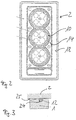
- Figur 1
- einen vertikalen Schnitt durch einen ölgekühlten Motorblock,
-
Figur 2 - einen horizontalen Schnitt durch einen Zylinderkopf und
-
Figur 3 - eine Zylinderkopfdichtung.
- FIG. 1
- a vertical section through an oil-cooled engine block,
- FIG. 2
- a horizontal section through a cylinder head and
- FIG. 3
- a cylinder head gasket.
Der in Figur 1 gezeigte Motorblock setzt sich bekanntermaßen aus vier Komponenten zusammen. So weist er ein zentrales Zylindergehäuse 1 und einen das Zylindergehäuse abdeckenden Zylinderkopf 2 auf. Unter dem Zylindergehäuse 1 ist ein Kurbelgehäuse 3 angeordnet und auf den Zylinderkopf 2 ist ein Ventildeckel 4 aufgesetzt. Ein Kolben 5 läuft innerhalb des Zylindergehäuses 1 in einer den Zylinder bildenden Laufbuchse 6 und ist bekanntermaßen durch Kolbenringe gegen die Laufbuchse 6 abgedichtet. Die Laufbuchse 6 umschließt damit den Hubraum des Kolbens 5. Weiterhin gezeigt sind die von herkömmlichen Motoren bekannten Ventile 7 und die Pleuelstange 8, die an der Kurbelwelle 9 angreift.The engine block shown in Figure 1 is known to be composed of four components. Thus, it has a central cylinder housing 1 and a
Erfindungsgemäß ist die Laufbuchse 6 und damit der Hubraum des Kolbens 5 von einem koaxialen Ringraum 10 umgeben, der von einem Ölstrom zum Zwecke der Kühlung beaufschlagt wird. Der Ringraum 10 setzt sich in einem Kopfraum 11 fort, der in den Zylinderkopf 2 eingebracht ist und der den Verbrennungsraum stirnseitig bedeckt. Kopfraum 11 und Ringraum 10 bilden einen den Zylinder bis auf die Durchführungen der Ventile 7 und der nicht dargestellten Einspritzdüse komplett umfassenden Kühlmantel, wobei durch eine als Brennraumdichtung ausgebildete Zylinderkopfdichtung 12 (s. Figur 3) aus Metall vermieden wird, daß Öl aus dem Kühlmantel in den Verbrennungsraum eintritt. Das für die Kühlung eingesetzte Öl wird in später zu beschreibender Weise von einem Vorratsbehälter dem Boden des Ringraumes 10 durch eine Eintrittsöffnung zugeführt, steigt im Ringraum 10 unter Abfuhr der im Zylinder entstandenen Wärme zum Zylinderkopf 2 auf und tritt in den Kopfraum 11 ein. Wie aus Figur 2 ersichtlich stehen die Ringräume 10 der in diesem Falle drei Zylinder untereinander in Verbindung.According to the invention, the
In die Kuppel des Kopfraumes 11 ist eine Austrittsöffnung 13 eingebracht, durch die das Öl in den Ventildeckel 4 entlang Pfeil A entweicht. Aus dem Ventildeckel 4 läuft das Öl von der Schwerkraft in einen Rücklaufraum 14, der den Zylinder unter Einschluß des Ringraumes 10 vollständig umgibt. An den Wänden dieses Rücklaufraumes 14 rinnt das Öl herunter, kühlt ab und sammelt sich am Boden in einem im Kurbelgehäuse 3 vorgesehenen Sammelraum 15. In dem Sammelraum 15 sammelt sich außerdem das Öl, das aus den Kolbenkühldüsen und den Gleitlagern austritt. Der Rücklaufraum 14 setzt sich aus ineinander übergehenden Kammern zusammen, die in den Zylinderkopf 2, das Zylindergehäuse 1 und das Kurbelgehäuse 3 eingebracht sind. Er umgibt somit den Zylinder und den Kolbenantrieb komplett. Wie aus Figur 2 ersichtlich, stehen die Rücklaufräume 14 der Zylinder untereinander in Verbindung und bilden einen die drei Zylinder umgebenden Rücklaufraum 14. Von dem Sammelraum 15 wird das Öl mittels einer elektrisch oder mechanisch betriebenen Pumpe 16 über eine Rückführleitung 17 in eine Vorratskammer 18 gepumpt, wobei es zunächst in einem Filter 19 von Rückständen befreit und von einen Ölkühler 20 zusätzlich gekühlt wird. Die Vorratskammer 18 steht mit dem Ringraum 10 über eine nicht dargestellte Leitung in Verbindung, so daß das Öl durch den von der Pumpe 16 aufgebauten Druck von der Vorratskammer 18 in den Ringraum 10 gedrückt wird. Die Vorratskammer 18 ist ebenfalls im Motorblock untergebracht und umgibt ihrerseits den kompletten Rücklaufraum 14. Sie setzt sich aus einzelnen Kompartementen sowohl im Kurbelgehäuse 3, im Zylindergehäuse 1, im Zylinderkopf 2 und im Ventildeckel 4 fort. Das in der Vorratskammer 18 gesammelte Öl wird sowohl für die Schmierung als auch für die Kühlung verwendet. Die Vorratskammer 18 ist über Dichtungen 23, die in diesem Falle aus Gummi gefertigt sind, gegenüber dem Außenraum abgedichtet. Ansonsten stehen Ringraum 10, Rücklaufraum 14 und Vorratskammer 18 an den Stößen zwischen den Komponenten des Motorblockes in einer durch den Spalt bedingten Verbindung.In the dome of the headspace 11, an
Über eine Bypaßleitung 21, die von der Rückführleitung 17 direkt in den Ringraum 10 führt und die mittels eines Drei-Wege-Ventiles 22 zugeschaltet wird, läßt sich das aufbereitete Öl direkt vom Sammelraum 15 in den Ringraum 10 pumpen. Dieses reduzierte Ölvolumen heizt sich schneller auf, so daß der Motor schnell seine Betriebstemperatur erreicht. Die Temperatur des Motors wird auf bekannte Weise von nicht dargestellten Temperatursensoren überwacht. Durch die Förderleistung der Pumpe 16 und den Einsatz der Bypaßleitung 21 kann dann die Temperatur des Motors gut kontrolliert werden. Die hinter dem Drei-Wege-Ventiles 22 fortgesetzte Rückführleitung 17 mündet in einen Einlaß 26 im Zylinderkopf. Von Außen ist das Öl dem System über einen Einlaß 27 zuführbar.Via a bypass line 21, which leads from the
Die Betriebstemperatur läßt sich bei dem erfindungsgemäßen Motor so einstellen, daß sie weit über 100°C hinausgeht und etwa 150° erreichen kann. Das ist möglich durch den Einsatz von Metalldichtungen für die Abdichtung zwischen Zylinderkopf und Zylinder. In diesem Fall ist die Metalldichtung ein Dichtring 12 (Figur 3), der in eine entsprechende die Zylinderbohrung umgebende Ringnut 24 in der Stoßfläche des Zylindergehäuses 1 eingelegt ist. Der Dichtring wird direkt von dem aufgeschraubten Zylinderkopf 2 quetschend beaufschlagt und dadurch verformt. Im Falle eines Zylinderkopfes aus Aluminium wird dieser an der entsprechen Stelle eingedrückt. Um die Dichtung 12 zu kühlen, bildet der Kühlmantel eine Kühlkammer 25 aus, über die der Ölstrom an den Dichtring 12 heranführbar ist. Die Kühlkammer 25 wird in diesem Falle von einer Verbreiterung des Spaltes zwischen dem Zylindergehäuse 1 und dem Zylinderkopf 2 gebildet.The operating temperature can be adjusted in the engine according to the invention so that it goes far beyond 100 ° C and can reach about 150 °. This is possible through the use of metal gaskets for sealing between cylinder head and cylinder. In this case, the metal gasket is a sealing ring 12 (Figure 3), which is inserted into a corresponding cylinder bore surrounding
Claims (10)
- An internal combustion engine with an engine block which has a cylinder housing and a cylinder head covering the cylinder housing, and which has a cooling jacket through oil flows, wherein the cooling jacket has an annular space (10) that at least partially and axially surrounds the working space of a piston(5) and a head space (11), wherein the head space (11) and the annular space (10) are connected directly to each other, and wherein the oil flow enters a return flow space (14) from the cooling jacket via an outlet port (13) incorporated in the head space (11), which return flow space fully surrounds at least one cylinder (6) with the inclusion of the annular space (10), characterised in that the head space (11) almost fully covers the working space on the front side.
- The internal combustion engine according to Claim 1, characterised in that the return flow space (14) opens in a collection space (15) arranged in the crankcase (3), wherein the oil flow runs into the collection space (15) driven by gravity.
- The internal combustion engine according to one of Claims 2 or 3, characterised in that several return flow spaces (14) surrounding the individual cylinders (6) are connected to each other and form a common return flow space.
- The internal combustion engine according to one of the preceding claims, characterised in that a storage chamber (18) is provided in the engine block which receives a supply of fresh oil and which at least fully surrounds a cylinder (6) and, in particular, all the cylinders.
- The internal combustion engine according to one of the preceding claims, characterised in that the oil can be conveyed via a bypass pipe (21) from the return pipe (17) directly into the annular space (10).
- The internal combustion engine according to one of the preceding claims, characterised in that the oil used for cooling is also used for lubricating the moving parts.
- The internal combustion engine according to one of the preceding claims, characterised in that the cylinder head is sealed against the cylinder housing by means of a metal seal.
- The internal combustion engine according to Claim 7, characterised in that the metal seal is a sealing ring (12), in particular an 0-ring, which rests in a groove (24) inserted in the front edge of the cylinder housing (1).
- The internal combustion engine according to Claim 7 or 8, characterised in that the cooling jacket has a cooling chamber (25) through which the oil flow is fed to the sealing ring (12).
- The internal combustion engine according to one of Claims 7 to 9, characterised in that the annular space (10) and the head space (11) pass flush inside one another at the point of the combustion space seal or cylinder head seal (12), and form a closed cooling jacket enclosing the working space of the cylinder.
Applications Claiming Priority (2)
| Application Number | Priority Date | Filing Date | Title |
|---|---|---|---|
| DE19940144A DE19940144A1 (en) | 1999-08-24 | 1999-08-24 | Oil-cooled internal combustion engine |
| DE19940144 | 1999-08-24 |
Publications (3)
| Publication Number | Publication Date |
|---|---|
| EP1079080A2 EP1079080A2 (en) | 2001-02-28 |
| EP1079080A3 EP1079080A3 (en) | 2002-07-24 |
| EP1079080B1 true EP1079080B1 (en) | 2006-06-21 |
Family
ID=7919451
Family Applications (1)
| Application Number | Title | Priority Date | Filing Date |
|---|---|---|---|
| EP00117193A Expired - Lifetime EP1079080B1 (en) | 1999-08-24 | 2000-08-11 | Oil cooled internal combustion engine |
Country Status (3)
| Country | Link |
|---|---|
| EP (1) | EP1079080B1 (en) |
| AT (1) | ATE331125T1 (en) |
| DE (2) | DE19940144A1 (en) |
Families Citing this family (8)
| Publication number | Priority date | Publication date | Assignee | Title |
|---|---|---|---|---|
| DE102004030353A1 (en) | 2004-06-23 | 2006-01-19 | Dr.Ing.H.C. F. Porsche Ag | Internal combustion engine with pressure circulation lubrication on the dry sump principle |
| DE102004030352A1 (en) | 2004-06-23 | 2006-01-19 | Dr.Ing.H.C. F. Porsche Ag | Internal combustion engine with pressure circulation lubrication on the dry sump principle |
| AP2009004853A0 (en) * | 2006-10-05 | 2009-06-30 | Hinderks M V | Improved reciprocating devices |
| FI20106227A (en) * | 2010-11-22 | 2012-05-23 | Waertsilae Finland Oy | ENGINE BLOCK SYSTEM AND METHOD FOR PREVENTION OF Friction Corrosion |
| DE102011084632B4 (en) | 2011-10-17 | 2015-03-05 | Ford Global Technologies, Llc | Method for heating an internal combustion engine and internal combustion engine for carrying out such a method |
| DE102016200269A1 (en) | 2016-01-13 | 2017-07-13 | Ford Global Technologies, Llc | Method for operating a liquid-cooled four-stroke internal combustion engine and four-stroke internal combustion engine for carrying out such a method |
| CN106050352B (en) * | 2016-08-15 | 2019-02-12 | 潍柴动力股份有限公司 | A kind of internal combustion engine and its main bearing lubrication system |
| DE102020115166A1 (en) | 2020-06-08 | 2021-12-09 | Audi Aktiengesellschaft | Drive device for a motor vehicle and method for operating a drive device |
Family Cites Families (10)
| Publication number | Priority date | Publication date | Assignee | Title |
|---|---|---|---|---|
| US3385273A (en) * | 1965-09-10 | 1968-05-28 | White Motor Corp | Cooling system for internal combustion engine |
| IT1048818B (en) * | 1975-11-03 | 1980-12-20 | Brighigna Mario | INTERNAL COMBUSTION ENGINE WITH CIRCULATION COOLING ONLY ONE LIQUID |
| IT1115349B (en) * | 1977-06-13 | 1986-02-03 | Brighigna Mario | INTERNAL COMBUSTION ENGINE COOLED BY LUBRICATION OIL |
| JPS5837920U (en) * | 1981-09-04 | 1983-03-11 | 三菱自動車工業株式会社 | engine cooling system |
| DE3508405A1 (en) * | 1984-03-13 | 1985-10-03 | Günter Elsbett | Internal combustion engine with reduced noise and heat emission |
| DE3509095A1 (en) * | 1984-04-11 | 1985-10-17 | Volkswagenwerk Ag, 3180 Wolfsburg | Arrangement for the cooling and lubrication of a reciprocating piston internal combustion engine |
| DE3638437A1 (en) * | 1986-11-11 | 1988-05-26 | Elsbett L | COOLING AND LUBRICATING CIRCUIT OF AN OIL-COOLED INTERNAL COMBUSTION ENGINE |
| DE3639691A1 (en) * | 1986-11-20 | 1988-06-01 | Kloeckner Humboldt Deutz Ag | DIESEL INTERNAL COMBUSTION ENGINE |
| DE4029427A1 (en) * | 1989-09-27 | 1991-04-04 | Volkswagen Ag | Piston-engine cylinder structure - has cooling jacket enclosed by oil vessel connected to lubrication system |
| JPH03264721A (en) * | 1990-03-14 | 1991-11-26 | Hino Motors Ltd | Block for heat insulating engine |
-
1999
- 1999-08-24 DE DE19940144A patent/DE19940144A1/en not_active Withdrawn
-
2000
- 2000-08-11 AT AT00117193T patent/ATE331125T1/en not_active IP Right Cessation
- 2000-08-11 EP EP00117193A patent/EP1079080B1/en not_active Expired - Lifetime
- 2000-08-11 DE DE50013028T patent/DE50013028D1/en not_active Expired - Fee Related
Also Published As
| Publication number | Publication date |
|---|---|
| DE50013028D1 (en) | 2006-08-03 |
| EP1079080A2 (en) | 2001-02-28 |
| ATE331125T1 (en) | 2006-07-15 |
| DE19940144A1 (en) | 2001-03-01 |
| EP1079080A3 (en) | 2002-07-24 |
Similar Documents
| Publication | Publication Date | Title |
|---|---|---|
| EP2305975B1 (en) | Combustion engine with pump for transporting engine oil and method for heating the engine oil of such a combustion engine | |
| DE3403176C2 (en) | Water-cooled multi-cylinder diesel engine | |
| DE2950905A1 (en) | COOLING DEVICE AND CYLINDER HEAD FOR COMBUSTION ENGINE | |
| DE3241723A1 (en) | TURNOVER ARRANGEMENT FOR CONTROLLING THE CHANGE OF CHARGE OF AN INTERNAL COMBUSTION ENGINE | |
| DE2825870A1 (en) | COMBUSTION ENGINE | |
| DE3832013C2 (en) | Reciprocating piston internal combustion engine with crankcase charge air pumps | |
| EP3339617A1 (en) | Cylinder housing, method for producing a cylinder housing and casting core | |
| DE102009030556B4 (en) | Turbocharger system for an internal combustion engine with a turbocharger mounting base with a reduced footprint | |
| EP1079080B1 (en) | Oil cooled internal combustion engine | |
| DE102013100017B4 (en) | Traction motor with oil cooler | |
| DE19818700A1 (en) | Internal combustion engine with an integrated front end | |
| DE60031343T2 (en) | INTERNAL COMBUSTION ENGINE WITH ROTATING CYLINDER BUSHES | |
| WO2006002791A1 (en) | Crankcase ventilation conduit | |
| DE19535920C2 (en) | Rotary vane control for an internal combustion engine or a piston pump | |
| DE3509095A1 (en) | Arrangement for the cooling and lubrication of a reciprocating piston internal combustion engine | |
| DE2910822C2 (en) | Air-cooled, rotary valve controlled four-stroke combustion engine | |
| DE102016100411A1 (en) | Hubkolbenvorrichtung and internal combustion engine with such a reciprocating piston device | |
| DE102006053923A1 (en) | Piston operating machine, has gas that is absorbed by inlet valve and compressed in compressor area, compressed gas is guided by internal space of housing on side away from compression area of stroke piston | |
| DE3622301A1 (en) | Internal combustion engine | |
| DE102004004050A1 (en) | Coolant pump arrangement for an internal combustion engine | |
| DE19727987C2 (en) | Two-stroke swashplate internal combustion engine | |
| DE202010012697U1 (en) | Box-type two-stroke internal combustion engine | |
| DE102020200039B4 (en) | Internal combustion engine with at least one liquid-cooled cylinder tube | |
| DE102019216820B4 (en) | Liquid-cooled internal combustion engine with at least one cylinder tube | |
| DE102007053493A1 (en) | Internal combustion engine has attachment surface provided broadly on drive unit cover for water pump carrier holding water pump on crankcase, and cylinder head is provided for cooling water pass over cooperating with water pump carrier |
Legal Events
| Date | Code | Title | Description |
|---|---|---|---|
| PUAI | Public reference made under article 153(3) epc to a published international application that has entered the european phase |
Free format text: ORIGINAL CODE: 0009012 |
|
| AK | Designated contracting states |
Kind code of ref document: A2 Designated state(s): AT BE CH CY DE DK ES FI FR GB GR IE IT LI LU MC NL PT SE |
|
| AX | Request for extension of the european patent |
Free format text: AL;LT;LV;MK;RO;SI |
|
| PUAL | Search report despatched |
Free format text: ORIGINAL CODE: 0009013 |
|
| AK | Designated contracting states |
Kind code of ref document: A3 Designated state(s): AT BE CH CY DE DK ES FI FR GB GR IE IT LI LU MC NL PT SE |
|
| AX | Request for extension of the european patent |
Free format text: AL;LT;LV;MK;RO;SI |
|
| 17P | Request for examination filed |
Effective date: 20030124 |
|
| AKX | Designation fees paid |
Designated state(s): AT BE CH CY DE DK ES FI FR GB GR IE IT LI LU MC NL PT SE |
|
| GRAP | Despatch of communication of intention to grant a patent |
Free format text: ORIGINAL CODE: EPIDOSNIGR1 |
|
| GRAS | Grant fee paid |
Free format text: ORIGINAL CODE: EPIDOSNIGR3 |
|
| GRAA | (expected) grant |
Free format text: ORIGINAL CODE: 0009210 |
|
| AK | Designated contracting states |
Kind code of ref document: B1 Designated state(s): AT BE CH CY DE DK ES FI FR GB GR IE IT LI LU MC NL PT SE |
|
| PG25 | Lapsed in a contracting state [announced via postgrant information from national office to epo] |
Ref country code: GB Free format text: LAPSE BECAUSE OF FAILURE TO SUBMIT A TRANSLATION OF THE DESCRIPTION OR TO PAY THE FEE WITHIN THE PRESCRIBED TIME-LIMIT Effective date: 20060621 Ref country code: IE Free format text: LAPSE BECAUSE OF FAILURE TO SUBMIT A TRANSLATION OF THE DESCRIPTION OR TO PAY THE FEE WITHIN THE PRESCRIBED TIME-LIMIT Effective date: 20060621 Ref country code: FI Free format text: LAPSE BECAUSE OF FAILURE TO SUBMIT A TRANSLATION OF THE DESCRIPTION OR TO PAY THE FEE WITHIN THE PRESCRIBED TIME-LIMIT Effective date: 20060621 Ref country code: NL Free format text: LAPSE BECAUSE OF FAILURE TO SUBMIT A TRANSLATION OF THE DESCRIPTION OR TO PAY THE FEE WITHIN THE PRESCRIBED TIME-LIMIT Effective date: 20060621 |
|
| REG | Reference to a national code |
Ref country code: GB Ref legal event code: FG4D Free format text: NOT ENGLISH |
|
| REG | Reference to a national code |
Ref country code: CH Ref legal event code: EP |
|
| REG | Reference to a national code |
Ref country code: IE Ref legal event code: FG4D Free format text: LANGUAGE OF EP DOCUMENT: GERMAN |
|
| REF | Corresponds to: |
Ref document number: 50013028 Country of ref document: DE Date of ref document: 20060803 Kind code of ref document: P |
|
| PG25 | Lapsed in a contracting state [announced via postgrant information from national office to epo] |
Ref country code: BE Free format text: LAPSE BECAUSE OF NON-PAYMENT OF DUE FEES Effective date: 20060831 Ref country code: CH Free format text: LAPSE BECAUSE OF NON-PAYMENT OF DUE FEES Effective date: 20060831 Ref country code: LI Free format text: LAPSE BECAUSE OF NON-PAYMENT OF DUE FEES Effective date: 20060831 Ref country code: MC Free format text: LAPSE BECAUSE OF NON-PAYMENT OF DUE FEES Effective date: 20060831 |
|
| PG25 | Lapsed in a contracting state [announced via postgrant information from national office to epo] |
Ref country code: DK Free format text: LAPSE BECAUSE OF FAILURE TO SUBMIT A TRANSLATION OF THE DESCRIPTION OR TO PAY THE FEE WITHIN THE PRESCRIBED TIME-LIMIT Effective date: 20060921 Ref country code: SE Free format text: LAPSE BECAUSE OF FAILURE TO SUBMIT A TRANSLATION OF THE DESCRIPTION OR TO PAY THE FEE WITHIN THE PRESCRIBED TIME-LIMIT Effective date: 20060921 |
|
| PG25 | Lapsed in a contracting state [announced via postgrant information from national office to epo] |
Ref country code: ES Free format text: LAPSE BECAUSE OF FAILURE TO SUBMIT A TRANSLATION OF THE DESCRIPTION OR TO PAY THE FEE WITHIN THE PRESCRIBED TIME-LIMIT Effective date: 20061002 |
|
| PG25 | Lapsed in a contracting state [announced via postgrant information from national office to epo] |
Ref country code: PT Free format text: LAPSE BECAUSE OF FAILURE TO SUBMIT A TRANSLATION OF THE DESCRIPTION OR TO PAY THE FEE WITHIN THE PRESCRIBED TIME-LIMIT Effective date: 20061121 |
|
| NLV1 | Nl: lapsed or annulled due to failure to fulfill the requirements of art. 29p and 29m of the patents act | ||
| REG | Reference to a national code |
Ref country code: IE Ref legal event code: FD4D |
|
| GBV | Gb: ep patent (uk) treated as always having been void in accordance with gb section 77(7)/1977 [no translation filed] |
Effective date: 20060621 |
|
| ET | Fr: translation filed | ||
| REG | Reference to a national code |
Ref country code: CH Ref legal event code: PL |
|
| PLBE | No opposition filed within time limit |
Free format text: ORIGINAL CODE: 0009261 |
|
| STAA | Information on the status of an ep patent application or granted ep patent |
Free format text: STATUS: NO OPPOSITION FILED WITHIN TIME LIMIT |
|
| 26N | No opposition filed |
Effective date: 20070322 |
|
| PG25 | Lapsed in a contracting state [announced via postgrant information from national office to epo] |
Ref country code: AT Free format text: LAPSE BECAUSE OF NON-PAYMENT OF DUE FEES Effective date: 20060811 |
|
| BERE | Be: lapsed |
Owner name: SUTTNER, REINHARD Effective date: 20060831 |
|
| PGFP | Annual fee paid to national office [announced via postgrant information from national office to epo] |
Ref country code: IT Payment date: 20070827 Year of fee payment: 8 |
|
| PG25 | Lapsed in a contracting state [announced via postgrant information from national office to epo] |
Ref country code: GR Free format text: LAPSE BECAUSE OF FAILURE TO SUBMIT A TRANSLATION OF THE DESCRIPTION OR TO PAY THE FEE WITHIN THE PRESCRIBED TIME-LIMIT Effective date: 20060922 |
|
| PGFP | Annual fee paid to national office [announced via postgrant information from national office to epo] |
Ref country code: FR Payment date: 20070821 Year of fee payment: 8 |
|
| PG25 | Lapsed in a contracting state [announced via postgrant information from national office to epo] |
Ref country code: LU Free format text: LAPSE BECAUSE OF NON-PAYMENT OF DUE FEES Effective date: 20060811 |
|
| PG25 | Lapsed in a contracting state [announced via postgrant information from national office to epo] |
Ref country code: CY Free format text: LAPSE BECAUSE OF FAILURE TO SUBMIT A TRANSLATION OF THE DESCRIPTION OR TO PAY THE FEE WITHIN THE PRESCRIBED TIME-LIMIT Effective date: 20060621 |
|
| PGFP | Annual fee paid to national office [announced via postgrant information from national office to epo] |
Ref country code: DE Payment date: 20081030 Year of fee payment: 9 |
|
| REG | Reference to a national code |
Ref country code: FR Ref legal event code: ST Effective date: 20090430 |
|
| PG25 | Lapsed in a contracting state [announced via postgrant information from national office to epo] |
Ref country code: FR Free format text: LAPSE BECAUSE OF NON-PAYMENT OF DUE FEES Effective date: 20080901 Ref country code: IT Free format text: LAPSE BECAUSE OF NON-PAYMENT OF DUE FEES Effective date: 20080811 |
|
| PG25 | Lapsed in a contracting state [announced via postgrant information from national office to epo] |
Ref country code: DE Free format text: LAPSE BECAUSE OF NON-PAYMENT OF DUE FEES Effective date: 20100302 |