EP0062030A1 - Reciprocating piston internal-combustion engine - Google Patents
Reciprocating piston internal-combustion engine Download PDFInfo
- Publication number
- EP0062030A1 EP0062030A1 EP82890045A EP82890045A EP0062030A1 EP 0062030 A1 EP0062030 A1 EP 0062030A1 EP 82890045 A EP82890045 A EP 82890045A EP 82890045 A EP82890045 A EP 82890045A EP 0062030 A1 EP0062030 A1 EP 0062030A1
- Authority
- EP
- European Patent Office
- Prior art keywords
- engine block
- combustion engine
- internal combustion
- casing
- crankshaft
- Prior art date
- Legal status (The legal status is an assumption and is not a legal conclusion. Google has not performed a legal analysis and makes no representation as to the accuracy of the status listed.)
- Granted
Links
Images


Classifications
-
- F—MECHANICAL ENGINEERING; LIGHTING; HEATING; WEAPONS; BLASTING
- F02—COMBUSTION ENGINES; HOT-GAS OR COMBUSTION-PRODUCT ENGINE PLANTS
- F02B—INTERNAL-COMBUSTION PISTON ENGINES; COMBUSTION ENGINES IN GENERAL
- F02B77/00—Component parts, details or accessories, not otherwise provided for
- F02B77/11—Thermal or acoustic insulation
- F02B77/13—Acoustic insulation
-
- Y—GENERAL TAGGING OF NEW TECHNOLOGICAL DEVELOPMENTS; GENERAL TAGGING OF CROSS-SECTIONAL TECHNOLOGIES SPANNING OVER SEVERAL SECTIONS OF THE IPC; TECHNICAL SUBJECTS COVERED BY FORMER USPC CROSS-REFERENCE ART COLLECTIONS [XRACs] AND DIGESTS
- Y10—TECHNICAL SUBJECTS COVERED BY FORMER USPC
- Y10S—TECHNICAL SUBJECTS COVERED BY FORMER USPC CROSS-REFERENCE ART COLLECTIONS [XRACs] AND DIGESTS
- Y10S277/00—Seal for a joint or juncture
- Y10S277/916—Seal including vibration dampening feature
Definitions
- the invention relates to a reciprocating internal combustion engine with an engine block consisting of cylinders, cylinder heads, crankshaft including engine, camshaft with control wheels and intake and exhaust manifold, which has an at least partially enclosing formwork, which is fastened to the engine block via structure-sound-insulating elements.
- the engine block has a circumferential side frame at approximately half the cylinder height, with which it is supported on the upper flat surface of a trough-shaped formwork with the interposition of a self-contained structure-borne sound-absorbing element
- Structure-borne noise-reducing element also forms the oil seal between the casing and the engine block.
- the upper area of the engine block protrudes from the trough-shaped casing and can be shielded by an additional sound-absorbing cover.
- the structure-borne sound-absorbing element must have a certain softness due to its sound-absorbing properties.
- an internal combustion engine has become known (AT-PS 308 475), in which the formwork is led out of a first group of shell parts attached directly to the engine to structure-borne sound insulation, through which existing pipelines and other motor connection parts are led, and from a second group of on the shell parts of the
- the first group consists of soundproof and easily detachable shell parts, which cover the parts of the engine or its auxiliary units that require maintenance and a shell part arranged over the rocker arm covers and covering the upper shell part of the cylinder head, two shell parts covering the crankcase side walls including any injection pump and one under the oil pan , include the lower shell part of the crankcase-closing shell part.
- the invention is therefore based on the object of eliminating these deficiencies and of creating a reciprocating internal combustion engine of the type described at the outset which, with reduced technical outlay, ensures the greatest possible sound insulation without having to accept radial relative movement between the crankshaft and clutch or transmission.
- the invention achieves the stated object in that the engine block, the flywheel housing and, if appropriate, the transmission are rigidly connected to one another in a manner known per se and are suspended directly as an aggregate in an elastic and structure-borne sound-absorbing manner, in that the casing forms an oil space that surrounds the engine block on all sides, and in that the sealing elements are designed in a ring shape and are arranged in the region of the end faces of the engine block.
- the formwork as such has no forces to transmit and also does not carry any auxiliary devices, it can be built very easily, for example in sheet metal or plastic, and it is not difficult to form it essentially in one piece and merely provide openings which can be closed by covers. It leads through the low mass of the formwork and its elastic fastening via the sealing elements on the engine block at most vibrations with very low amplitudes, so that the necessary security of the seals is guaranteed. Since the formwork surrounds the engine block on all sides, there is no need for a separate cover for the area of the cylinder heads, so that the number of connection points which are difficult to seal is reduced.
- the ring-shaped sealing elements in the area of the end faces of the engine block result in the shortest possible sealing lengths and the simplest possible assembly.
- the engine block is rigidly connected to the flywheel housing and possibly the transmission to form an aggregate, no radial relative movements can occur between the crankshaft and the clutch or the transmission.
- This unit is itself suspended elastically and structure-borne noise, so that further sound transmission is prevented and the introduction of forces into the formwork is avoided.
- the auxiliary devices such as alternator, water pump, filter, oil cooler, compressor and / or. are connected to the unit formed with elastic and structure-borne sound insulation. Like., attached. This avoids stressing the formwork on the part of these auxiliary devices, and the wall thickness of the formwork can be kept very small. In addition, the vibrating mass of the formwork is of course also reduced, so that there are, if at all, only very small vibration amplitudes with respect to the engine block.
- a bearing plate which is coaxial with the crankshaft and serves as a cover, is fastened to the crossmember with a bearing for the shaft of the drive of the auxiliary devices, and this shaft is connected to the crankshaft via an elastic coupling which isolates structure-borne noise. Since the drive shaft of the auxiliary devices is mounted in the bearing plate attached to the cross member, there are no relative movements between the auxiliary devices and the drive shaft. On the other hand, the radial relative movements between the crankshaft and the drive shaft for the auxiliary devices resulting from the elastic mounting of the unit formed in the cross member can take place unhindered and without harmful effects.
- the end shield has the further advantage that it covers the crankshaft end together with the vibration damper that is usually present in a noise-absorbing manner.
- lateral eyes with a rubber lining are provided in the flywheel housing, in which support pins for the unit formed are stored. This prevents the sound from being transmitted to the outside of the flywheel housing via the trunnions.
- the casing has an elongated opening in the area of the exhaust manifold, which is closed by a housing surrounding the exhaust manifold with the interposition of an elastic and structure-borne sound-absorbing seal, so that the exhaust manifold is also soundproofed.
- the housing is attached to the cylinder heads with the interposition of a structure-borne sound-absorbing seal, and the edge of the formwork opening nestles against the housing with the interposition of an elastic seal, which consists of layers separated from one another by heat-resistant and structure-borne sound-insulating flat seals.
- an elastic seal which consists of layers separated from one another by heat-resistant and structure-borne sound-insulating flat seals.
- the flywheel housing can have its own casing supported on it or on the trunnion under structure-borne sound insulation, optionally enclosing the starter, to which a gearbox casing can then be connected.
- the starter is in the usual way on the flywheel attached to the housing and thus does not perform any relative movements with respect to the flywheel.
- the engine block I is enclosed on all sides by a casing 9, the u-a removable cover-10 to make the valve rocker arms accessible. Like. And has an oil pan 11 and forms an oil space.
- the casing 9 is fastened to the engine block I via structure-borne noise-isolating sealing elements 12, 13, the sealing elements 12, 13 being arranged on the end faces of the engine block I and being designed in a ring shape.
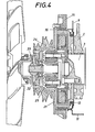
- a cross member 15 with the interposition of an elastic and structure-borne sound-absorbing ring 16, with the cross Carrier 15, which in turn is supported on longitudinal beams 17 of a chassis, auxiliary devices such as alternator 18, water pump 19 and compressor 20 (Fig. 3) are attached.
- a bearing plate 21 which is coaxial with the crankshaft 3 and serves as a cover, is screwed onto the cross member 15 and is provided with a bearing 22 for the shaft 23 of the drive pulley 24 for the auxiliary devices 18, 19, 20.
- the shaft 23 is connected to the crankshaft 3 via an elastic coupling 25 which isolates structure-borne noise.
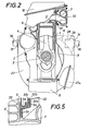
- the flywheel housing 8 has its own formwork 27 supported on it with the interposition of structure-borne sound-absorbing rings 26, which part 27a also encloses the starter. Furthermore, 8 eyes 28 are provided in the flywheel housing according to FIG. 2, which have a rubber lining 29 and are used to mount support pins 30 for the unit formed.
- the cladding 27 of the flywheel housing 8 is supported on the trunnion 30 also by means of structure-borne rings 31.
- the casing 9 has an elongated opening in the region of the exhaust manifold 7, which opening is closed by a housing 32 surrounding the exhaust manifold 7.
- the edge 9a of the opening of the casing 9 nestles against the housing 32 with the interposition of an elastic seal 33 (see in particular FIG. 5), which in this edge region of the opening consists of layers 32a, 32b, 32c separated by heat-resistant and structure-borne sound insulation 34 consists.
Abstract
Eine Hubkolben-Brennkraftmaschine weist einen Triebwerksblock (I) auf, der aus den Zylindern (1), den Zylinderköpfen (2), der Kurbelwelle (3) samt dem von dem Kurbelkröpfungen und den Pleueln (4) gebildeten Triebwerk, der Nockenwelle (5) mit den Steuerungsrädern (6) und der Ansaug- sowie Abgassammelleitung (7) besteht. Der Triebwerksblock (I) ist mit einer ihn wenigstens teilweise umschließenden Verschalung (9) versehen. Diese Verschalung (9) ist über körperschallisolierende Dichtelemente (12, 13) am Triebwerksblock (I) befestigt. Um den technischen Aufwand zu verringern und eine weitestgehende Schalldämmung zu erzielen, ohne radiale Relativbewegungen zwischen Kurbelwelle (3) und Kupplung bzw. Getriebe in Kauf nehmen zu müssen, sind der Triebwerksblock (I), das Schwungradgehäuse (8) und gegebenenfalls das Getriebe zu einem Aggregat starr miteinander verbunden, das unmittelbar elastisch und körperschalldämmend aufgehängt ist. Ferner bildet die Verschalung (9) einen wenigstens den Triebwerksblock (I) allseits umgebenden Olraum. Schließlich sind die Dichtelemente (12, 13) ringförmig gestaltet und im Bereich der Stirnseiten des Triebwerksblockes (I) angeordnet.A reciprocating piston internal combustion engine has an engine block (I) which consists of the cylinders (1), the cylinder heads (2), the crankshaft (3) together with the engine, the camshaft and the connecting rods (4), the camshaft (5) with the steering wheels (6) and the intake and exhaust manifold (7). The engine block (I) is provided with a casing (9) which at least partially surrounds it. This casing (9) is fastened to the engine block (I) via sealing elements (12, 13) that isolate structure-borne noise. The engine block (I), the flywheel housing (8) and, if applicable, the gearbox are one to reduce the technical effort and achieve the greatest possible sound insulation without having to accept radial relative movements between the crankshaft (3) and clutch or gearbox Unit rigidly connected to each other, which is suspended directly elastic and structure-borne noise. Furthermore, the casing (9) forms an oil space which surrounds at least the engine block (I) on all sides. Finally, the sealing elements (12, 13) have an annular design and are arranged in the region of the end faces of the engine block (I).
Description
Die Erfindung betrifft eine Hubkolben-Brennkraftmaschine mit einem aus Zylindern, Zylinderköpfen, Kurbelwelle samt Triebwerk, Nockenwelle mit Steuerungsrädern und Ansaug- sowie Abgassammelleitung bestehenden Triebwerksblock, der eine ihn wenigstens teilweise umschließende Verschalung aufweist, die über körperschallisolierende Dichtelemente am Triebwerksblock befestigt ist.The invention relates to a reciprocating internal combustion engine with an engine block consisting of cylinders, cylinder heads, crankshaft including engine, camshaft with control wheels and intake and exhaust manifold, which has an at least partially enclosing formwork, which is fastened to the engine block via structure-sound-insulating elements.
Bei einer bekannten Hubkolben-Brennkraftmaschine (DE-OS 26 12 182) weist der Triebwerksblock etwa in halber Zylinderhöhe einen umlaufenden Seitenrahmen auf, mit dem er unter Zwischenlage eines in sich ringförmig geschlossenen körperschalldämmenden Elementes auf der oberen Planfläche einer wannenförmigen Verschalung abgestützt ist, wobei das körperschalldämmende Element zugleich die öldichtung zwischen der Verschalung und dem Triebwerksblock bildet. Der obere Bereich des Triebwerksblockes ragt aus der wannenförmigen Verschalung heraus und kann durch eine zusätzliche schalldämmende Abdeckhaube abgeschirmt werden. Das körperschalldämmende Element muß auf Grund seiner schalldämmenden Eigenschaften eine gewisse Weichheit aufweisen. Da es nun aber zugleich das Stützelement für den Triebwerksblock darstellt und außer durch die Masse des Triebwerksblockes auch vom Motordrehmoment belastet ist, das gegenüber der wannenförmigen Verschalung abgestützt werden muß, ergeben sich in ungünstiger Weise beträchtliche Ausschläge des Kurbelwellenmittels in radialer Richtung. Die unausgeglichenen Massenlräfte und -momente der Kurbeltriebwerke können zusätzlich zu Resonanzen und verstärkten Ausschlägen der Kurbelwellen führen, da der ganze Triebwerksblock innerhalb der Verschalung mehr oder weniger pendelnd aufgehängt ist. Schließlich ist auch die axiale Führung des Triebwerksblockes, z.B. gegenüber etwaigen Schubkräften von der Kupplung her, nicht ausreichend gewährleistet. Auf Grund dieser allseitigen Beweglichkeit der Kurbelwelle und damit des Schwungrades ist es unmöglich, unmittelbar an diesem in bewährter Weise den weiteren Antrieb bzw. die Kupplung anzuordnen. Es ist vielmehr erforderlich, eine vergleichsweise komplizierte elastische Zwischenkupplung vorzusehen, die den Raumbedarf, den Bauaufwand und auch das Maschinengewicht erhöht.In a known reciprocating piston internal combustion engine (DE-OS 26 12 182), the engine block has a circumferential side frame at approximately half the cylinder height, with which it is supported on the upper flat surface of a trough-shaped formwork with the interposition of a self-contained structure-borne sound-absorbing element Structure-borne noise-reducing element also forms the oil seal between the casing and the engine block. The upper area of the engine block protrudes from the trough-shaped casing and can be shielded by an additional sound-absorbing cover. The structure-borne sound-absorbing element must have a certain softness due to its sound-absorbing properties. But since it now also represents the support element for the engine block and besides being burdened by the mass of the engine block also by the engine torque, which has to be supported against the trough-shaped casing, there are unfavorable deflections of the crankshaft means in the radial direction. The unbalanced mass forces and moments of the crank engines can additionally lead to resonances and increased deflections of the crank shafts, since the whole engine block is suspended more or less pendulum within the casing. Finally, the axial guidance of the engine block, for example with respect to any thrust forces from the clutch, is not sufficiently guaranteed. Due to this all-round mobility of the crankshaft and thus of the flywheel, it is impossible to arrange the further drive or the clutch directly on it in a proven manner. Rather, it is necessary to provide a comparatively complicated elastic intermediate coupling which increases the space requirement, the construction effort and also the weight of the machine.
Eine Verbesserung brachte eine andere bekannte Konstruktion (DE-AS 28 01 431), bei der der Triebwerksblock an seinen beiden Stirnseiten zur Kurbelwelle koaxiale, als Stützelemente dienende Dämmringe aufweist, mit denen er in der wannenförmigen Verschalung zentriert gehalten und axial festgelegt ist, während zwischen dem Triebwerksblock und dem oberen Rand der wannenförmigen Verschalung lediglich eine Öldichtung sitzt. Da der Triebwerksblock in diesem Fall in der Verschalung zentriert gehalten ist, kann er keine Pendelbewegungen mit sich verändernder Lage des Kurbelwellenmittels ausführen. Es hat sich aber gezeigt, daß bei Brennkraftmaschinen mit größerem Hubvolumen die notwendige Verformbarkeit der Dämmringe doch zu merkbaren Relativausschlägen des Triebwerksblockes gegenüber der Verschalung in radialer Richtung zur Kurbelwelle führt. Außerdem ergeben sich wegen der möglichen Relativbewegungen des Triebwerksblockes um die Kurbelwellenachse Schwierigkeiten bei der Abdichtung zwischen der Verschalung und dem Triebwerksblock.An improvement brought another known construction (DE-AS 28 01 431), in which the engine block on both ends of the crankshaft has coaxial, serving as support elements insulating rings, with which it is centered in the trough-shaped casing and axially fixed, while between the engine block and the upper edge of the trough-shaped casing only an oil seal sits. In this case, since the engine block is kept centered in the casing, it cannot execute any oscillating movements with a changing position of the crankshaft means. However, it has been shown that with internal combustion machines with a larger stroke volume the necessary deformability of the insulation rings leads to noticeable relative deflections of the engine block compared to the casing in the radial direction to the crankshaft. In addition, because of the possible relative movements of the engine block around the crankshaft axis, difficulties arise in the sealing between the casing and the engine block.
Schließlich ist eine Brennlraftmaschine bekannt geworden (AT-PS 308 475), bei der die Verschalung aus einer ersten Gruppe von direkt am Motor körperschallisolierend befestigten Schalenteilen, durch die vorhandene Rohrleitungen und sonstige Motoranschlußteile herausgeführt sind, sowie aus einer zweiten Gruppe von an den Schalenteilen der ersten Gruppe schalldicht und leicht lösbar befestigten Schalenteilen besteht, welche die wartungsbedürftigen Stellen des Motors oder seiner Hilfsaggregate bedecken und einen über den Kipphebelabdeckungen angeordneten, den oberen Schalenteil des Zylinderkopfes abdeckenden Schalenteil, zwei die Kurbelgehäuseseitenwände einschließlich einer allfälligen Einspritzpumpe überdeckende Schalenteile und einen unter der Ölwanne angebrachten, den unteren Schalenteil des Kurbelgehäuses abschließenden Schalenteil umfassen. Hier handelt es sich also um eine Vielzahl von untereinander und gegen den Motor abzudichtenT den Schalenteilen, die den Bauaufwand beträchtlich erhöhen und eine entsprechend große Zahl von Dichtungen bzw. Dämmkörpern erfordern, wobei der Aufwand auch dadurch erhöht wird, daß nicht ein Triebwerksblock, sondern ein ganzer Motor mit einem Kurbelgehäuse zu verschalen ist. Die zur Motoraufhängung erforderlichen Konsolen od. dgl. sind ohne schalldämmende Isolierung bzw. Abdeckung am Motor bzw. am Kurbelgehäuse befestigt und tragen so zur Schallabgabe nach außen bei, so daß trotz der Verschalung keine befriedigende Schalldämmung erzielbar ist.Finally, an internal combustion engine has become known (AT-PS 308 475), in which the formwork is led out of a first group of shell parts attached directly to the engine to structure-borne sound insulation, through which existing pipelines and other motor connection parts are led, and from a second group of on the shell parts of the The first group consists of soundproof and easily detachable shell parts, which cover the parts of the engine or its auxiliary units that require maintenance and a shell part arranged over the rocker arm covers and covering the upper shell part of the cylinder head, two shell parts covering the crankcase side walls including any injection pump and one under the oil pan , include the lower shell part of the crankcase-closing shell part. This is a large number of shell parts that have to be sealed against each other and against the engine, which considerably increase the construction effort and require a correspondingly large number of seals or insulating bodies, the effort also being increased by the fact that not one engine block but one the entire engine is to be boarded with a crankcase. The engine up suspension required brackets or the like. Are attached to the engine or crankcase without soundproofing insulation or cover and thus contribute to the sound emission to the outside, so that despite the casing no satisfactory soundproofing can be achieved.
Demnach liegt der Erfindung die Aufgabe zugrunde, diese Mängel zu beseitigen und eine Hubkolben-Brennkraftmaschine der eingangs geschilderten Art zu schaffen, die bei verringertem technischem Aufwand eine weitestgehende Schalldämmung gewährleistet, ohne radiale Relativbewegung zwischen Kurbelwelle und Kupplung bzw. Getriebe in Kauf nehmen zu müssen.The invention is therefore based on the object of eliminating these deficiencies and of creating a reciprocating internal combustion engine of the type described at the outset which, with reduced technical outlay, ensures the greatest possible sound insulation without having to accept radial relative movement between the crankshaft and clutch or transmission.
Die Erfindung löst die gestellte Aufgabe dadurch, daß der Triebwerksblock, das Schwungradgehäuse und gegebenenfalls das Getriebe in an sich bekannter Weise starr miteinander verbunden und als Aggregat unmittelbar elastisch und körperschalldämmend aufgehängt sind, daß die Verschalung einen wenigstens den Triebwerksblock allseits umgebenden Ölraum bildet, und daß die Dichtelemente ringförmig gestaltet und im Bereich der Stirnseiten des Triebwerksblockes angeordnet sind.The invention achieves the stated object in that the engine block, the flywheel housing and, if appropriate, the transmission are rigidly connected to one another in a manner known per se and are suspended directly as an aggregate in an elastic and structure-borne sound-absorbing manner, in that the casing forms an oil space that surrounds the engine block on all sides, and in that the sealing elements are designed in a ring shape and are arranged in the region of the end faces of the engine block.
Da also die Verschalung als solche keine Kräfte zu übertragen hat und auch keine Hilfseinrichtungen trägt, kann sie sehr leicht, z.B. in Blech oder Kunststoff, gebaut werden, wobei es keine Schwierigkeiten bereitet, sie im wesentlichen einstückig auszubilden und bloß durch Deckel verschließbare Öffnungen vorzusehen. Durch die geringe Masse der Verschalung und ihre elastische Befestigung über die Dichtelemente am Triebwerksblock führt sie höchstens Schwingungen mit sehr geringen Amplituden aus, so daß die notwendige Sicherheit der Dichtungen gewährleistet ist. Da die Verschalung den Triebwerksblock allseits umschließt, erübrigt sich eine eigene Abdeckung für den Bereich der Zylinderköpfe, so daß die Anzahl der schwer abzudichtenden Verbindungsstellen verringert wird. Die ringförmigen Dichtelemente im Bereich der Stirnseiten des Triebwerksblockes ergeben geringstmögliche Dichtlängen und eine einfachste Montagemoglichkeit. Da der Triebwerksblock mit dem Schwungradgehäuse und gegebenenfalls dem Getriebe zu einem Aggregat starr verbunden ist, können zwischen der Kurbelwelle und der Kupplung bzw. dem Getriebe keine radialen Relatibewegungen auftreten. Dabei ist dieses Aggregat selbst elastisch und körperschalldämmend aufgehängt, so daß eine weitere Schallübertragung hintangehalten und eine Einleitung von Kräften in die Verschalung vermieden wird.So since the formwork as such has no forces to transmit and also does not carry any auxiliary devices, it can be built very easily, for example in sheet metal or plastic, and it is not difficult to form it essentially in one piece and merely provide openings which can be closed by covers. It leads through the low mass of the formwork and its elastic fastening via the sealing elements on the engine block at most vibrations with very low amplitudes, so that the necessary security of the seals is guaranteed. Since the formwork surrounds the engine block on all sides, there is no need for a separate cover for the area of the cylinder heads, so that the number of connection points which are difficult to seal is reduced. The ring-shaped sealing elements in the area of the end faces of the engine block result in the shortest possible sealing lengths and the simplest possible assembly. Since the engine block is rigidly connected to the flywheel housing and possibly the transmission to form an aggregate, no radial relative movements can occur between the crankshaft and the clutch or the transmission. This unit is itself suspended elastically and structure-borne noise, so that further sound transmission is prevented and the introduction of forces into the formwork is avoided.
Ist das dem Schwungrad abgekehrte Ende des gebildeten Aggregates an einem Querträger aufgehängt, so sind erfindungsgemäß an diesem mit dem gebildeten Aggregat elastisch und körperschall - dämmend verbundenen Querträger die Hilfseinrichtungen, wie Lichtmaschine, Wasserpumpe, Filter, Ölkühler, Kompressor und/od. dgl., befestigt. Dadurch wird eine Belastung der Verschalung seitens dieser Hilfseinrichtungen vermieden, und es kann die Wanddicke der Verschalung sehr gering gehalten werden. Außerdem wird selbstverständlich auch die schwingende Masse der Verschalung verringert, so daß sich, wenn überhaupt, nur ganz geringe Schwingungsamplituden gegenüber dem Triebwerksblock ergeben.If the end of the unit formed opposite the flywheel is suspended from a cross member, then according to the invention the auxiliary devices, such as alternator, water pump, filter, oil cooler, compressor and / or. Are connected to the unit formed with elastic and structure-borne sound insulation. Like., attached. This avoids stressing the formwork on the part of these auxiliary devices, and the wall thickness of the formwork can be kept very small. In addition, the vibrating mass of the formwork is of course also reduced, so that there are, if at all, only very small vibration amplitudes with respect to the engine block.
Erfindungsgemäß ist an dem Querträger ein zur Kurbelwelle koaxialer, zur Abdeckung dienender Lagerschild mit einer Lagerung für die Welle des Antriebes der Hilfseinrichtungen befestigt, und es steht diese Welle mit der Kurbelwelle über eine elastische, körperschallisolierende Kupplung in Verbindung. Da die Antriebswelle der Hilfseinrichtungen in dem am Querträger befestigten Lagerschild gelagert ist, ergeben sich zwischen den Hilfseinrichtungen und der Antriebswelle keine Relativbewegungen. Dagegen können die sich aus der elastischen Lagerung des gebildeten Aggregates im Querträger ergebenden radialen Relativbewegungen zwischen der Kurbelwelle und der Antriebswelle für die Hilfseinrichtungen zufolge der elastischen Kupplung unbehindert und ohne schädliche Auswirkungen erfolgen. Der Lagerschild hat noch den weiteren Vorteil, daß er das Kurbelwellenende samt dem in der Regel vorhandenen Schwingungsdämpfer geräuschdämmend abdeckt. Es besteht auch die Möglichkeit, den Lüfterring samt dem Lüfterschacht am Querträger starr zu befestigen und den Lüfterantrieb von der Welle des Antriebes der Hilfseinrichtungen abzuleiten, so daß auch radiale Relativbewegungen zwischen Lüfterrad und Lüfterring vermieden werden und der Lüfterspalt zur Verbesserung des Wirkungsgrades klein gehalten werden kann.According to the invention, a bearing plate, which is coaxial with the crankshaft and serves as a cover, is fastened to the crossmember with a bearing for the shaft of the drive of the auxiliary devices, and this shaft is connected to the crankshaft via an elastic coupling which isolates structure-borne noise. Since the drive shaft of the auxiliary devices is mounted in the bearing plate attached to the cross member, there are no relative movements between the auxiliary devices and the drive shaft. On the other hand, the radial relative movements between the crankshaft and the drive shaft for the auxiliary devices resulting from the elastic mounting of the unit formed in the cross member can take place unhindered and without harmful effects. The end shield has the further advantage that it covers the crankshaft end together with the vibration damper that is usually present in a noise-absorbing manner. There is also the possibility of rigidly attaching the fan ring together with the fan shaft to the crossmember and deriving the fan drive from the shaft of the drive of the auxiliary devices, so that radial relative movements between the fan wheel and fan ring can be avoided and the fan gap can be kept small to improve the efficiency .
Zur weiteren körperschalldämmenden Aufhängung des gebildeten Aggregates sind im Schwungradgehäuse seitliche, eine Gummiausfütterung aufweisende Augen vorgesehen, in denen Tragzapfen für das gebildete Aggregat lagern. Dadurch wird eine Weiterleitung des Schalls vom Schwungradgehäuse über die Tragzapfen nach außen verhindert.For further structure-borne sound-absorbing suspension of the unit formed, lateral eyes with a rubber lining are provided in the flywheel housing, in which support pins for the unit formed are stored. This prevents the sound from being transmitted to the outside of the flywheel housing via the trunnions.
Die Verschalung weist im Bereich der Abgassammelleitung eine längliche Öffnung auf, die durch ein die Abgassammelleitung umschließendes Gehäuse unter Zwischenlage einer elastischen und körperschalldämmenden Dichtung verschlossen ist, so daß auch die Abgassammelleitung schalldämmend abgeschirmt ist.The casing has an elongated opening in the area of the exhaust manifold, which is closed by a housing surrounding the exhaust manifold with the interposition of an elastic and structure-borne sound-absorbing seal, so that the exhaust manifold is also soundproofed.
Dabei ist das Gehäuse unter Zwischenlage einer körperschalldämmenden Dichtung an den Zylinderköpfen befestigt, und es schmiegt sich der Rand der Verschalungsöffnung unter Zwischenlage einer elastischen Dichtung an das Gehäuse an, das im Randbereich der Öffnung aus untereinander durch wärmebeständige und körperschalldämmende Flachdichtungen getrennten Schichten besteht. Obwohl also das Gehäuse nicht an der dünnen Verschalung, sondern an den Zylinderköpfen befestigt ist, wird ein dichter und schallisolierter Anschluß sowohl der Verschalung an dem Gehäuse als auch des Gehäuses an dem betreffenden Zylinderkopf erzielt, wobei die Mehrschichtigkeit der Gehäusewand im Randbereich der Öffnung dafür sorgt, daß die elastische Dichtung der Verschalung vor zu großer Erwärmung bewahrt bleibt. Selbstverständlich könnte die mehrschichtige Gehäusewand auch durch einen einstückigen Dichtkörper geeigneten Materials ersetzt werden.The housing is attached to the cylinder heads with the interposition of a structure-borne sound-absorbing seal, and the edge of the formwork opening nestles against the housing with the interposition of an elastic seal, which consists of layers separated from one another by heat-resistant and structure-borne sound-insulating flat seals. Thus, although the housing is not attached to the thin casing, but to the cylinder heads, a tight and sound-insulated connection of both the casing on the housing and the housing to the relevant cylinder head is achieved, the multilayered nature of the housing wall in the edge region of the opening ensuring this that the elastic seal of the formwork is protected from excessive heating. Of course, the multi-layer housing wall could also be replaced by a one-piece sealing body of suitable material.
Um eine noch bessere Schalldämmung zu erzielen, kann das Schwungradgehäuse eine eigene an ihm bzw. an den Tragzapfen unter Körperschalldämmung abgestützte, den Anlasser gegebenenfalls mitumschließende Verschalung aufweisen, an die dann eine Getriebeverschalung anschließbar ist. Dabei ist der Anlasser in üblicher Weise am Schwungradgehäuse befestigt und führt somit dem Schwungrad gegenüber keine Relativbewegungen aus.In order to achieve an even better sound insulation, the flywheel housing can have its own casing supported on it or on the trunnion under structure-borne sound insulation, optionally enclosing the starter, to which a gearbox casing can then be connected. The starter is in the usual way on the flywheel attached to the housing and thus does not perform any relative movements with respect to the flywheel.
In der Zeichnung ist der Erfindungsgegenstand beispielsweise dargestellt, und zwar zeigen
- Fig. 1 eine mehrzylindrige Hubkolben-Brennkraftmaschine im vertikalen Längsschnitt,
- Fig. 2 im vertikalen Querschnitt,
- Fig. 3 in Stirnansicht bei abgenommenem Lüfterrad,
- Fig. 4 den Antrieb des Lüfterrades und der Hilfseinrichtungen vergrößert im Axialschnitt und
- Fig. 5 die Befestigung des die Abgassammelleitung umschließenden Gehäuses als Detail ebenfalls im größeren Maßstab.
- 1 is a multi-cylinder reciprocating internal combustion engine in vertical longitudinal section,
- 2 in vertical cross section,
- 3 in front view with the fan wheel removed,
- Fig. 4 enlarged the drive of the fan wheel and the auxiliary devices in axial section and
- Fig. 5 shows the attachment of the housing surrounding the exhaust manifold as a detail also on a larger scale.
Die Zylinder 1, die Zylinderköpfe 2, die Kurbelwelle 3 samt dem von den Kurbelkröpfungen und den Pleueln 4 gebildeten Triebwerk, die Nockenwelle 5 mit den Steuerungsrädern 6 und die Ansaug- sowie Abgassammelleitung 7 bilden einen Triebwerksblock I, der kein eigenes Kurbelgehäuse aufweist, aber mit dem Schwungradgehäuse 8 zu einem Aggregat starr verbunden ist, an das sich ebenfalls in starrer Verbindung das nicht dargestellte Getriebe anschließen kann. Der Triebwerksblock I wird allseits von einer Verschalung 9 umschlossen, die einen abnehmbaren Deckel-10 zum Zugänglichmachen der Ventilkipphebel u. dgl. sowie eine Ölwanne 11 besitzt und einen Ölraum bildet. Die Verschalung 9 ist über körperschallisolierende Dichtelemente 12, 13 am Triebwerksblock I befestigt, wobei die Dichtelemente 12, 13 an den Stirnseiten des Triebwerksblockes I angeordnet und ringförmig gestaltet sind.The
Das dem Schwungrad 14 abgekehrte Ende des gebildeten Aggregates ist an einem Querträger 15 unter Zwischenlage eines elastischen und körperschalldämmenden Ringes 16 aufgehängt, wobei an dem Querträger 15, der sich seinerseits an Längsträgern 17 eines Fahrgestelles abstützt, Hilfseinrichtungen, wie Lichtmaschine 18, Wasserpumpe 19 und Kompressor 20 (Fig. 3), befestigt sind. Gemäß Fig. 4 ist an dem Querträger 15 ein zur Kurbelwelle 3 koaxialer, zur Abdeckung dienender Lagerschild 21 angeschraubt, der mit einer Lagerung 22 für die Welle 23 der Antriebsriemenscheibe 24 für die Hilfseinrichtungen 18, 19, 20 versehen ist. Die Welle 23 ist mit der Kurbelwelle 3 über eine elastische, körperschallisolierende Kupplung 25 verbunden. Das Schwungradgehäuse 8 weist eine eigene, an ihm unter Zwischenlage körperschalldämmender Ringe 26 abgestützte Verschalung 27 auf, die mit ihrem Teil 27a auch den Anlasser umschließt. Ferner sind gemäß Fig. 2 im Schwungradgehäuse 8 Augen 28 vorgesehen, die eine Gummiausfütterung 29 aufweisen und zur Lagerung von Tragzapfen 30 für das gebildete Aggregat dienen. Die Verschalung 27 des Schwungradgehäuses 8 stützt sich an den Tragzapfen 30 ebenfalls über körperschalldämmende Ringe 31 ab.The end facing away from the
Die Verschalung 9 weist im Bereich der Abgassammelleitung 7 eine längliche Öffnung auf, die durch ein die Abgassammelleitung 7 umschließendes Gehäuse 32 verschlossen ist. Der Rand 9a der Öffnung der Verschalung 9 schmiegt sich unter Zwischenlage einer elastischen Dichtung 33 (siehe insbesondere Fig. 5) an das Gehäuse 32 an, das in diesem Randbereich der Öffnung aus durch wärmebeständige und körperschalldämmende Flachdichtungen 34 voneinander getrennten Schichten 32a, 32b, 32c besteht.The
Claims (7)
Applications Claiming Priority (2)
| Application Number | Priority Date | Filing Date | Title |
|---|---|---|---|
| AT1487/81 | 1981-03-31 | ||
| AT0148781A AT387624B (en) | 1981-03-31 | 1981-03-31 | PISTON PISTON ENGINE |
Publications (2)
| Publication Number | Publication Date |
|---|---|
| EP0062030A1 true EP0062030A1 (en) | 1982-10-06 |
| EP0062030B1 EP0062030B1 (en) | 1985-07-10 |
Family
ID=3514955
Family Applications (1)
| Application Number | Title | Priority Date | Filing Date |
|---|---|---|---|
| EP82890045A Expired EP0062030B1 (en) | 1981-03-31 | 1982-03-24 | Reciprocating piston internal-combustion engine |
Country Status (7)
| Country | Link |
|---|---|
| US (1) | US4480608A (en) |
| EP (1) | EP0062030B1 (en) |
| JP (1) | JPS57176345A (en) |
| AT (1) | AT387624B (en) |
| CA (1) | CA1189454A (en) |
| DE (1) | DE3264630D1 (en) |
| YU (1) | YU43512B (en) |
Cited By (3)
| Publication number | Priority date | Publication date | Assignee | Title |
|---|---|---|---|---|
| EP0252178A1 (en) * | 1986-07-10 | 1988-01-13 | MAN Nutzfahrzeuge Aktiengesellschaft | Shell for the drive engine in a motor vehicle |
| EP0307388A2 (en) * | 1987-09-09 | 1989-03-15 | STEYR-DAIMLER-PUCH Aktiengesellschaft | Sound-absorbing encapsulation for an internal-combustion engine |
| EP0315622A2 (en) * | 1987-11-03 | 1989-05-10 | Steyr-Daimler-Puch Aktiengesellschaft | Connection of the crankshaft of an insulated internal combustion engine to the coaxial drive shaft of auxiliary devices arranged outside the encapsulation, on a transverse carrier |
Families Citing this family (8)
| Publication number | Priority date | Publication date | Assignee | Title |
|---|---|---|---|---|
| DE3408011A1 (en) * | 1984-03-03 | 1985-09-05 | Klein, Schanzlin & Becker Ag, 6710 Frankenthal | SEALING FOR PARTIAL FLANGE AND SEALING HOUSING OF LONG-SIDED MACHINE HOUSINGS |
| US4669432A (en) * | 1986-05-16 | 1987-06-02 | Kabushiki Kaisha Komatsu Seisakusho | Sealing device for an oil pan adapter in an internal combustion engine |
| ATA108690A (en) * | 1990-05-16 | 1994-12-15 | Laimboeck Franz | LIQUID-COOLED INTERNAL COMBUSTION ENGINE |
| US5665019A (en) * | 1996-02-05 | 1997-09-09 | Ford Global Technologies, Inc. | Chain guide mounting assembly for the reduction of chain induced noise and vibration in a chain driven overhead cam internal combustion engine |
| US6178939B1 (en) * | 1998-06-24 | 2001-01-30 | Siemens Canada Limited | Housing system |
| DE10358117A1 (en) * | 2003-12-12 | 2005-07-14 | Man Nutzfahrzeuge Ag | gasket |
| AT503764B1 (en) * | 2007-09-06 | 2009-01-15 | Avl List Gmbh | FLYWHEEL HOUSING |
| CN112682621B (en) * | 2020-12-21 | 2023-01-20 | 中国北方发动机研究所(天津) | Split type flywheel housing structure of integrated oil circuit |
Citations (6)
| Publication number | Priority date | Publication date | Assignee | Title |
|---|---|---|---|---|
| GB145062A (en) * | 1915-12-18 | 1920-12-09 | Daimler Motoren | Improvements in and connected with means for preventing the transmission of sound and vibration from machines and parts thereof |
| US2875746A (en) * | 1956-05-09 | 1959-03-03 | Gen Motors Corp | Engine accessory support means |
| DE2043280A1 (en) * | 1969-09-08 | 1971-04-15 | List, Hans, Dipl Ing Prof Dr Dr h c , Graz (Österreich) | Internal combustion engine with sound-absorbing casing |
| DE1775468A1 (en) * | 1967-08-21 | 1972-04-06 | List Hans | Internal combustion engine with noise-dampening casing |
| FR2307964A1 (en) * | 1975-04-18 | 1976-11-12 | List Hans | REDUCED NOISE COMBUSTION ENGINE |
| DE2801431A1 (en) * | 1977-12-07 | 1979-06-13 | Steyr Daimler Puch Ag | Piston engine fitter in outer trough - has centring damper rings at ends of cylinder block coaxial to crankshaft |
Family Cites Families (9)
| Publication number | Priority date | Publication date | Assignee | Title |
|---|---|---|---|---|
| US3263663A (en) * | 1963-09-09 | 1966-08-02 | Crusader Marine Corp | Engine |
| US3863936A (en) * | 1973-03-27 | 1975-02-04 | Farnam Co F D | High temperature gasket structure and method of producing same |
| GB1451707A (en) * | 1974-07-26 | 1976-10-06 | British Uralite Ltd | Noise control materials |
| JPS5516090Y2 (en) * | 1976-03-26 | 1980-04-15 | ||
| US4137888A (en) * | 1976-11-24 | 1979-02-06 | Allis-Chalmers Corporation | Sound abatement device for internal combustion engine |
| DE2804833A1 (en) * | 1977-02-24 | 1978-08-31 | List Hans | QUIET COMBUSTION ENGINE |
| DE2736378C2 (en) * | 1977-08-12 | 1985-12-19 | Klöckner-Humboldt-Deutz AG, 5000 Köln | Auxiliary machines for the air-cooled internal combustion engine of a tractor |
| AT365309B (en) * | 1977-08-18 | 1982-01-11 | List Hans | INTERNAL COMBUSTION ENGINE WITH SOUND-INSULATING PANELING |
| AT374569B (en) * | 1979-02-07 | 1984-05-10 | List Hans | INTERNAL COMBUSTION ENGINE |
-
1981
- 1981-03-31 AT AT0148781A patent/AT387624B/en not_active IP Right Cessation
-
1982
- 1982-03-18 US US06/359,279 patent/US4480608A/en not_active Expired - Fee Related
- 1982-03-24 DE DE8282890045T patent/DE3264630D1/en not_active Expired
- 1982-03-24 EP EP82890045A patent/EP0062030B1/en not_active Expired
- 1982-03-30 CA CA000399768A patent/CA1189454A/en not_active Expired
- 1982-03-30 JP JP57050258A patent/JPS57176345A/en active Granted
- 1982-03-31 YU YU718/82A patent/YU43512B/en unknown
Patent Citations (6)
| Publication number | Priority date | Publication date | Assignee | Title |
|---|---|---|---|---|
| GB145062A (en) * | 1915-12-18 | 1920-12-09 | Daimler Motoren | Improvements in and connected with means for preventing the transmission of sound and vibration from machines and parts thereof |
| US2875746A (en) * | 1956-05-09 | 1959-03-03 | Gen Motors Corp | Engine accessory support means |
| DE1775468A1 (en) * | 1967-08-21 | 1972-04-06 | List Hans | Internal combustion engine with noise-dampening casing |
| DE2043280A1 (en) * | 1969-09-08 | 1971-04-15 | List, Hans, Dipl Ing Prof Dr Dr h c , Graz (Österreich) | Internal combustion engine with sound-absorbing casing |
| FR2307964A1 (en) * | 1975-04-18 | 1976-11-12 | List Hans | REDUCED NOISE COMBUSTION ENGINE |
| DE2801431A1 (en) * | 1977-12-07 | 1979-06-13 | Steyr Daimler Puch Ag | Piston engine fitter in outer trough - has centring damper rings at ends of cylinder block coaxial to crankshaft |
Non-Patent Citations (1)
| Title |
|---|
| AUTOMOBILTECHNISCHE ZEITSCHRIFT, Band 74, Nr. 7, Juli 1972, Seiten 261-268, Stuttgart, DE. * |
Cited By (7)
| Publication number | Priority date | Publication date | Assignee | Title |
|---|---|---|---|---|
| EP0252178A1 (en) * | 1986-07-10 | 1988-01-13 | MAN Nutzfahrzeuge Aktiengesellschaft | Shell for the drive engine in a motor vehicle |
| EP0307388A2 (en) * | 1987-09-09 | 1989-03-15 | STEYR-DAIMLER-PUCH Aktiengesellschaft | Sound-absorbing encapsulation for an internal-combustion engine |
| US4836160A (en) * | 1987-09-09 | 1989-06-06 | Steyr-Daimler-Puch Aktiengesellschaft | Internal combustion engine provided with a sound-insulating enclosure |
| EP0307388A3 (en) * | 1987-09-09 | 1989-11-29 | Steyr-Daimler-Puch Aktiengesellschaft | Sound-absorbing encapsulation for an internal-combustion engine |
| EP0315622A2 (en) * | 1987-11-03 | 1989-05-10 | Steyr-Daimler-Puch Aktiengesellschaft | Connection of the crankshaft of an insulated internal combustion engine to the coaxial drive shaft of auxiliary devices arranged outside the encapsulation, on a transverse carrier |
| DE3831002A1 (en) * | 1987-11-03 | 1989-05-18 | Steyr Daimler Puch Ag | CONNECTION OF THE CRANKSHAFT OF A SOUND-ENCLOSED INTERNAL COMBUSTION ENGINE WITH THE COAXIAL DRIVE SHAFT OF THE AUXILIARIES OUTSIDE THE CAPSULE |
| EP0315622A3 (en) * | 1987-11-03 | 1989-11-23 | Steyr-Daimler-Puch Aktiengesellschaft | Connection of the crankshaft of an insulated internal combustion engine to the coaxial drive shaft of auxiliary devices arranged outside the encapsulation, on a transverse carrier |
Also Published As
| Publication number | Publication date |
|---|---|
| JPS6315471B2 (en) | 1988-04-05 |
| US4480608A (en) | 1984-11-06 |
| YU71882A (en) | 1985-03-20 |
| YU43512B (en) | 1989-08-31 |
| DE3264630D1 (en) | 1985-08-14 |
| CA1189454A (en) | 1985-06-25 |
| AT387624B (en) | 1989-02-27 |
| JPS57176345A (en) | 1982-10-29 |
| EP0062030B1 (en) | 1985-07-10 |
| ATA148781A (en) | 1988-07-15 |
Similar Documents
| Publication | Publication Date | Title |
|---|---|---|
| DE1576775C3 (en) | Internal combustion engine with sound-insulating casing | |
| DE1775468C3 (en) | Internal combustion engine with noise-absorbing casing | |
| DE1914162C3 (en) | Air-cooled single cylinder internal combustion engine | |
| DE2612182C3 (en) | Noise-insulated reciprocating internal combustion engine | |
| EP0062030A1 (en) | Reciprocating piston internal-combustion engine | |
| DE2738063A1 (en) | MOTOR VEHICLE WITH A SOUND-INSULATING COMBUSTION ENGINE SUPPORTED ON ITS TWO FRAMEWORKS | |
| DE2922030A1 (en) | COMBUSTION MACHINE | |
| DE2638009A1 (en) | MULTICYLINDER COMBUSTION ENGINE | |
| DE2801431A1 (en) | Piston engine fitter in outer trough - has centring damper rings at ends of cylinder block coaxial to crankshaft | |
| DE2920081C2 (en) | Internal combustion engine, the engine carrier of which is supported on the crankcase by means of force-transmitting and structure-borne noise insulating elements | |
| DE2065889A1 (en) | COMBUSTION MACHINE WITH SOUND-INSULATING CASING | |
| EP0435847B1 (en) | Reciprocating internal combustion piston engine | |
| DE3532599C2 (en) | ||
| DE4141881C2 (en) | Silenced reciprocating internal combustion engine | |
| AT394759B (en) | INTERNAL COMBUSTION ENGINE WITH LIQUID COOLING | |
| EP0030597B1 (en) | Internal combustion engine with injection pumps arrangement | |
| EP0457750B1 (en) | Internal combustion engine with cooling liquid | |
| AT394758B (en) | INTERNAL COMBUSTION ENGINE | |
| EP0683857A1 (en) | Piston engine, especially piston internal combustion engine with reinforced engine block using segmented ribs | |
| DE3634454A1 (en) | DRIVE UNIT CONSISTING OF PISTON PISTON ENGINE, TRANSMISSION AND DRIVE SHAFT | |
| AT400742B (en) | Internal combustion engine with reciprocating pistons | |
| AT399916B (en) | Internal combustion engine having a soundproofing cowling | |
| AT402536B (en) | Internal combustion engine having reciprocating pistons | |
| DE1751124C (en) | Crankcase for internal combustion engines | |
| DE2043280C3 (en) | Internal combustion engine with sound-absorbing casing |
Legal Events
| Date | Code | Title | Description |
|---|---|---|---|
| PUAI | Public reference made under article 153(3) epc to a published international application that has entered the european phase |
Free format text: ORIGINAL CODE: 0009012 |
|
| AK | Designated contracting states |
Designated state(s): DE FR GB IT NL SE |
|
| 17P | Request for examination filed |
Effective date: 19821016 |
|
| ITF | It: translation for a ep patent filed |
Owner name: MODIANO & ASSOCIATI S.R.L. |
|
| GRAA | (expected) grant |
Free format text: ORIGINAL CODE: 0009210 |
|
| AK | Designated contracting states |
Designated state(s): DE FR GB IT NL SE |
|
| REF | Corresponds to: |
Ref document number: 3264630 Country of ref document: DE Date of ref document: 19850814 |
|
| ET | Fr: translation filed | ||
| PLBE | No opposition filed within time limit |
Free format text: ORIGINAL CODE: 0009261 |
|
| STAA | Information on the status of an ep patent application or granted ep patent |
Free format text: STATUS: NO OPPOSITION FILED WITHIN TIME LIMIT |
|
| 26N | No opposition filed | ||
| ITTA | It: last paid annual fee | ||
| PGFP | Annual fee paid to national office [announced via postgrant information from national office to epo] |
Ref country code: GB Payment date: 19940215 Year of fee payment: 13 |
|
| PGFP | Annual fee paid to national office [announced via postgrant information from national office to epo] |
Ref country code: FR Payment date: 19940218 Year of fee payment: 13 |
|
| PGFP | Annual fee paid to national office [announced via postgrant information from national office to epo] |
Ref country code: SE Payment date: 19940223 Year of fee payment: 13 |
|
| PGFP | Annual fee paid to national office [announced via postgrant information from national office to epo] |
Ref country code: NL Payment date: 19940331 Year of fee payment: 13 |
|
| EAL | Se: european patent in force in sweden |
Ref document number: 82890045.6 |
|
| PG25 | Lapsed in a contracting state [announced via postgrant information from national office to epo] |
Ref country code: GB Effective date: 19950324 |
|
| PG25 | Lapsed in a contracting state [announced via postgrant information from national office to epo] |
Ref country code: SE Effective date: 19950325 |
|
| PG25 | Lapsed in a contracting state [announced via postgrant information from national office to epo] |
Ref country code: NL Effective date: 19951001 |
|
| GBPC | Gb: european patent ceased through non-payment of renewal fee |
Effective date: 19950324 |
|
| PG25 | Lapsed in a contracting state [announced via postgrant information from national office to epo] |
Ref country code: FR Free format text: LAPSE BECAUSE OF NON-PAYMENT OF DUE FEES Effective date: 19951130 |
|
| NLV4 | Nl: lapsed or anulled due to non-payment of the annual fee |
Effective date: 19951001 |
|
| EUG | Se: european patent has lapsed |
Ref document number: 82890045.6 |
|
| REG | Reference to a national code |
Ref country code: FR Ref legal event code: ST |
|
| PGFP | Annual fee paid to national office [announced via postgrant information from national office to epo] |
Ref country code: DE Payment date: 20010313 Year of fee payment: 20 |