EP0062014A1 - Ablassventil - Google Patents
Ablassventil Download PDFInfo
- Publication number
- EP0062014A1 EP0062014A1 EP82850029A EP82850029A EP0062014A1 EP 0062014 A1 EP0062014 A1 EP 0062014A1 EP 82850029 A EP82850029 A EP 82850029A EP 82850029 A EP82850029 A EP 82850029A EP 0062014 A1 EP0062014 A1 EP 0062014A1
- Authority
- EP
- European Patent Office
- Prior art keywords
- valve
- valve member
- container
- valve assembly
- float
- Prior art date
- Legal status (The legal status is an assumption and is not a legal conclusion. Google has not performed a legal analysis and makes no representation as to the accuracy of the status listed.)
- Withdrawn
Links
Images

Classifications
-
- F—MECHANICAL ENGINEERING; LIGHTING; HEATING; WEAPONS; BLASTING
- F16—ENGINEERING ELEMENTS AND UNITS; GENERAL MEASURES FOR PRODUCING AND MAINTAINING EFFECTIVE FUNCTIONING OF MACHINES OR INSTALLATIONS; THERMAL INSULATION IN GENERAL
- F16T—STEAM TRAPS OR LIKE APPARATUS FOR DRAINING-OFF LIQUIDS FROM ENCLOSURES PREDOMINANTLY CONTAINING GASES OR VAPOURS
- F16T1/00—Steam traps or like apparatus for draining-off liquids from enclosures predominantly containing gases or vapours, e.g. gas lines, steam lines, containers
- F16T1/20—Steam traps or like apparatus for draining-off liquids from enclosures predominantly containing gases or vapours, e.g. gas lines, steam lines, containers with valves controlled by floats
- F16T1/22—Steam traps or like apparatus for draining-off liquids from enclosures predominantly containing gases or vapours, e.g. gas lines, steam lines, containers with valves controlled by floats of closed-hollow-body type
Definitions
- the present invention relates to a drain valve assembly for a compressed gas system.
- a common way of taking care of the liquid is to collect it in a container having a float operated valve.
- the float opens the valve and the liquid is expelled by the gas pressure.
- the valve is closed again by the float.
- the valve member is connected to the float by a lever or a lever system.
- the purpose of the present invention is to provide a drain valve assembly which is capable of proper operation over extended periods of time. This is obtained with a drain valve assembly as claimed.
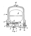
- the embodiment shown in fig 1 comprises a container 1, which can be a separate container for the drain valve assembly as shown or the compressed gas storage tank.
- Container 1 comprises an upper part 11, provided with an inlet opening 15 for the entry of condensed liquid from the compressed gas system, and a lower part 12.
- the lower part is provided with an outlet channel 3 through which condensed liquid is expelled as described below.
- the lower part is further provided with a portion 8 situated below a valve seat 5 mounted on lower part 12.
- Portion 8 is intended for collection of dirt that may be present in the liquid. Such dirt may be drained through channel 14 and manual drain valve 9.
- Valve seat 5 is made of a dirt repellant plastic material, having good corrosion resistance, for example DELRIN (trade mark), and is provided with a flow communication 7 and a flat surface 6.
- Lower part 12 is further provided with an access port 10, normally plugged, in axial alignment with flow communication 7.
- a valve member 2 is mounted on lower part 12 by means of a screw 13.
- Valve member 2 is made of a flexible sheet material being a dirt repellant plastic material, having good corrosion resistance, preferably VITON (trade mark).
- a float 4 having a stud 16 is fixed to valve member 2. Through access port 10 it is possible to check the operation of the valve and to clean flow communication 7 with a simple tool. This can be done during normal operation of the valve assembly.
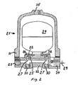
- the embodiment shown in fig 2 comprises a container 21 as in the fig 1 embodiment.
- Container 21 comprises an upper part 31 having an inlet opening 35 and a lower part 32 being provided with an outlet channel 23.
- the lower part is furthermore provided with flow communications 27 normally covered by a valve member 22.
- the flow communications are provided in an annular valve seat 25 having a substantially flat surface 26 for cooperation with valve member 22.
- a float 24 having a stud 36 is fixed to valve member 22 for actuation thereof.
- the materials of valve seat 25 and valve member 22 are preferably the same as in the fig 1 embodiment.
- the operation of the fig 2 embodiment is similar to that of the fig 1 embodiment. In this embodiment the valve member is not fixed to the container.
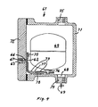
- the embodiment shown in fig 3 comprises a container 41 as in the fig 1 embodiment.
- Container 41 comprises an upper part 51 having an inlet opening 55 and a lower part 52 being provided with an outlet channel 43.
- the lower part is furthermore provided with a flow communication 47 normally covered by a valve member 42.
- the flow communication is provided in a valve seat 45 having a flat surface 46 for cooperation with valve member 42.
- the lower part is provided with an access port 50 in axial alignment with flow communication 47.
- a float 44 having a stud 56 is fixed to valve member 42, which in this case is made of an elastic tube which is not fixed to the container. As in the fig 2 embodiment proper operation is guaranteed because the float is guided by the container.
- valve seat 45 for collection of dirt which can be drained through channel 54 and manual drain valve 49.
- the materials of valve seat 45 and valve member 42 are preferably the same as in the fig 1 embodiment.
- the operation of the fig 3 embodiment is similar to that of the fig 2 embodiment.
- the embodiment shown in fig 4 comprises a container 61 having a mounting plate 72 and a cover 71.
- Cover 71 is provided with an inlet opening 75, a lower portion 68 for collection of dirt which is drainable through a channel 74 and manual drain valve 69.
- Mounting plate 72 is provided with a flow communication 67 through which liquid is drained to outlet channel .63.
- Plate 72 is furthermore provided with a flat surface 66'for cooperation with a valve member 62 being fixed to plate 72 by means of a screw 73. In this case flow communication 67 is situated higher above the bottom of the container than in the other embodiments. This means that the risk for clogging is smaller so that a special material valve seat can be avoided as shown in the drawing.
Landscapes
- Engineering & Computer Science (AREA)
- General Engineering & Computer Science (AREA)
- Mechanical Engineering (AREA)
- Self-Closing Valves And Venting Or Aerating Valves (AREA)
- Float Valves (AREA)
Applications Claiming Priority (2)
| Application Number | Priority Date | Filing Date | Title |
|---|---|---|---|
| SE8101943 | 1981-03-26 | ||
| SE8101943A SE425691B (sv) | 1981-03-26 | 1981-03-26 | Dreneringsventilanordning |
Publications (1)
| Publication Number | Publication Date |
|---|---|
| EP0062014A1 true EP0062014A1 (de) | 1982-10-06 |
Family
ID=20343443
Family Applications (1)
| Application Number | Title | Priority Date | Filing Date |
|---|---|---|---|
| EP82850029A Withdrawn EP0062014A1 (de) | 1981-03-26 | 1982-02-18 | Ablassventil |
Country Status (5)
| Country | Link |
|---|---|
| EP (1) | EP0062014A1 (de) |
| JP (1) | JPS57171198A (de) |
| AU (1) | AU8190282A (de) |
| FI (1) | FI820666A7 (de) |
| SE (1) | SE425691B (de) |
Cited By (5)
| Publication number | Priority date | Publication date | Assignee | Title |
|---|---|---|---|---|
| GB2159927A (en) * | 1984-06-04 | 1985-12-11 | Smith Corp A O | Condensate discharge device for combustion apparatus |
| US4627460A (en) * | 1984-06-04 | 1986-12-09 | A. D. Smith Corporation | Condensate discharge device for combustion apparatus |
| EP0793053A1 (de) * | 1996-02-29 | 1997-09-03 | Atlas Copco Airpower N.V. | Vorrichtung für die Beseitigung von Flüssigkeiten und/oder Verunreinigungen aus einem Gas |
| CN110594571A (zh) * | 2019-09-17 | 2019-12-20 | 华陆工程科技有限责任公司 | 一种带油汽回收功能的钢制浮顶用自动通气阀 |
| DE102019130798A1 (de) * | 2019-11-14 | 2021-05-20 | Dürr Dental SE | Schwimmerventil, Druckluftsystem mit einem Schwimmerventil und Trockner für ein Druckluftsystem mit einem Schwimmerventil |
Families Citing this family (1)
| Publication number | Priority date | Publication date | Assignee | Title |
|---|---|---|---|---|
| JPS60131800U (ja) * | 1984-02-14 | 1985-09-03 | 株式会社 小金井製作所 | 圧縮空気のドレン排出装置 |
Citations (4)
| Publication number | Priority date | Publication date | Assignee | Title |
|---|---|---|---|---|
| US2043074A (en) * | 1932-07-28 | 1936-06-02 | Hoffman Specialty Company | Steam trap |
| US2957490A (en) * | 1955-11-03 | 1960-10-25 | Liquid Controls Corp | Fluid segregators |
| US3437104A (en) * | 1966-10-12 | 1969-04-08 | Liquid Controls Corp | Combined air eliminator and vacuum breaker |
| FR2136633A5 (de) * | 1971-04-26 | 1972-12-22 | Liquid Controls Corp |
-
1981
- 1981-03-26 SE SE8101943A patent/SE425691B/sv unknown
-
1982
- 1982-02-18 EP EP82850029A patent/EP0062014A1/de not_active Withdrawn
- 1982-02-25 FI FI820666A patent/FI820666A7/fi not_active Application Discontinuation
- 1982-03-25 AU AU81902/82A patent/AU8190282A/en not_active Abandoned
- 1982-03-25 JP JP57046480A patent/JPS57171198A/ja active Pending
Patent Citations (4)
| Publication number | Priority date | Publication date | Assignee | Title |
|---|---|---|---|---|
| US2043074A (en) * | 1932-07-28 | 1936-06-02 | Hoffman Specialty Company | Steam trap |
| US2957490A (en) * | 1955-11-03 | 1960-10-25 | Liquid Controls Corp | Fluid segregators |
| US3437104A (en) * | 1966-10-12 | 1969-04-08 | Liquid Controls Corp | Combined air eliminator and vacuum breaker |
| FR2136633A5 (de) * | 1971-04-26 | 1972-12-22 | Liquid Controls Corp |
Cited By (10)
| Publication number | Priority date | Publication date | Assignee | Title |
|---|---|---|---|---|
| GB2159927A (en) * | 1984-06-04 | 1985-12-11 | Smith Corp A O | Condensate discharge device for combustion apparatus |
| US4627460A (en) * | 1984-06-04 | 1986-12-09 | A. D. Smith Corporation | Condensate discharge device for combustion apparatus |
| EP0793053A1 (de) * | 1996-02-29 | 1997-09-03 | Atlas Copco Airpower N.V. | Vorrichtung für die Beseitigung von Flüssigkeiten und/oder Verunreinigungen aus einem Gas |
| BE1010051A3 (nl) * | 1996-02-29 | 1997-12-02 | Atlas Copco Airpower Nv | Inrichting voor het verwijderen van vloeistoffen en/of onreinheden uit een gas. |
| US5769911A (en) * | 1996-02-29 | 1998-06-23 | Atlas Copco Airpower, N.V. | Device for the removal of liquid and solid contaminants from a gas |
| CN110594571A (zh) * | 2019-09-17 | 2019-12-20 | 华陆工程科技有限责任公司 | 一种带油汽回收功能的钢制浮顶用自动通气阀 |
| CN110594571B (zh) * | 2019-09-17 | 2024-05-28 | 华陆工程科技有限责任公司 | 一种带油汽回收功能的钢制浮顶用自动通气阀 |
| DE102019130798A1 (de) * | 2019-11-14 | 2021-05-20 | Dürr Dental SE | Schwimmerventil, Druckluftsystem mit einem Schwimmerventil und Trockner für ein Druckluftsystem mit einem Schwimmerventil |
| WO2021094298A1 (de) * | 2019-11-14 | 2021-05-20 | Dürr Dental SE | Schwimmerventil, druckluftsystem mit einem schwimmerventil und trockner für ein druckluftsystem mit einem schwimmerventil |
| DE102019130798B4 (de) | 2019-11-14 | 2021-09-16 | Dürr Dental SE | Schwimmerventil, Druckluftsystem mit einem Schwimmerventil und Trockner für ein Druckluftsystem mit einem Schwimmerventil |
Also Published As
| Publication number | Publication date |
|---|---|
| SE425691B (sv) | 1982-10-25 |
| AU8190282A (en) | 1982-09-30 |
| JPS57171198A (en) | 1982-10-21 |
| FI820666L (fi) | 1982-09-27 |
| FI820666A7 (fi) | 1982-09-27 |
Similar Documents
| Publication | Publication Date | Title |
|---|---|---|
| US5053120A (en) | Arrangement for draining water collecting in the container of a water separator of an internal-combustion engine | |
| EP0062014A1 (de) | Ablassventil | |
| GB2081232A (en) | Fuel supply and return systems | |
| US3642176A (en) | Means for storing and dispensing heated liquid and system therefor | |
| US3160169A (en) | Check valve unit for a diaphragm type pressure regulator | |
| US4378254A (en) | Method for simultaneously cleaning and skimming a vessel containing a liquid | |
| US4574829A (en) | Automatic drain valve | |
| US5533545A (en) | Drain system | |
| MXPA03011577A (es) | Aspiradora con captura continua de liquido. | |
| DE69703630T2 (de) | Vorrichtung für die Beseitigung von Flüssigkeiten und/oder Verunreinigungen aus einem Gas | |
| GB2159927A (en) | Condensate discharge device for combustion apparatus | |
| GB2199402A (en) | A drainage device for an air conditioner | |
| US2875991A (en) | Humidifier | |
| US4922947A (en) | Automatic membrane drain device for pneumatic circuits | |
| DE2620380C3 (de) | Entlüftungseinrichtung für flüssigkeitsgefüllte Leitungssysteme | |
| US4252142A (en) | Apparatus for discontinuously diluting a liquid in another liquid, to a given level of concentration | |
| SE8401692D0 (sv) | Automatic valve for draining condensate on compressed air systems | |
| US2854993A (en) | Differential pressure liquid level and moisture control device | |
| WO2003052303A1 (en) | A fluid release system | |
| JP2508238Y2 (ja) | 冷房機における吸引式ドレン強制排出装置 | |
| DE69215880D1 (de) | Automatisches entleerungsventil für ein druckluftfilter | |
| JPH0662275U (ja) | フロート式逆止弁 | |
| RU2194210C2 (ru) | Сливное устройство | |
| JPH0515931Y2 (de) | ||
| SU1089342A1 (ru) | Конденсатоотводчик |
Legal Events
| Date | Code | Title | Description |
|---|---|---|---|
| PUAI | Public reference made under article 153(3) epc to a published international application that has entered the european phase |
Free format text: ORIGINAL CODE: 0009012 |
|
| AK | Designated contracting states |
Designated state(s): AT BE DE FR GB IT NL |
|
| STAA | Information on the status of an ep patent application or granted ep patent |
Free format text: STATUS: THE APPLICATION IS DEEMED TO BE WITHDRAWN |
|
| 18D | Application deemed to be withdrawn |
Effective date: 19830915 |
|
| RIN1 | Information on inventor provided before grant (corrected) |
Inventor name: SIENACK, DESIDERATUS JULIUS |