EP0061756B1 - Apparatus for the surface-treatment of buildings and ships - Google Patents
Apparatus for the surface-treatment of buildings and ships Download PDFInfo
- Publication number
- EP0061756B1 EP0061756B1 EP82102621A EP82102621A EP0061756B1 EP 0061756 B1 EP0061756 B1 EP 0061756B1 EP 82102621 A EP82102621 A EP 82102621A EP 82102621 A EP82102621 A EP 82102621A EP 0061756 B1 EP0061756 B1 EP 0061756B1
- Authority
- EP
- European Patent Office
- Prior art keywords
- nozzle
- pressure
- outlet nozzle
- shunt
- blasting
- Prior art date
- Legal status (The legal status is an assumption and is not a legal conclusion. Google has not performed a legal analysis and makes no representation as to the accuracy of the status listed.)
- Expired
Links
Images
Classifications
-
- B—PERFORMING OPERATIONS; TRANSPORTING
- B63—SHIPS OR OTHER WATERBORNE VESSELS; RELATED EQUIPMENT
- B63B—SHIPS OR OTHER WATERBORNE VESSELS; EQUIPMENT FOR SHIPPING
- B63B59/00—Hull protection specially adapted for vessels; Cleaning devices specially adapted for vessels
- B63B59/06—Cleaning devices for hulls
-
- B—PERFORMING OPERATIONS; TRANSPORTING
- B05—SPRAYING OR ATOMISING IN GENERAL; APPLYING FLUENT MATERIALS TO SURFACES, IN GENERAL
- B05B—SPRAYING APPARATUS; ATOMISING APPARATUS; NOZZLES
- B05B17/00—Apparatus for spraying or atomising liquids or other fluent materials, not covered by the preceding groups
-
- B—PERFORMING OPERATIONS; TRANSPORTING
- B05—SPRAYING OR ATOMISING IN GENERAL; APPLYING FLUENT MATERIALS TO SURFACES, IN GENERAL
- B05B—SPRAYING APPARATUS; ATOMISING APPARATUS; NOZZLES
- B05B7/00—Spraying apparatus for discharge of liquids or other fluent materials from two or more sources, e.g. of liquid and air, of powder and gas
- B05B7/14—Spraying apparatus for discharge of liquids or other fluent materials from two or more sources, e.g. of liquid and air, of powder and gas designed for spraying particulate materials
- B05B7/1481—Spray pistols or apparatus for discharging particulate material
- B05B7/1486—Spray pistols or apparatus for discharging particulate material for spraying particulate material in dry state
-
- B—PERFORMING OPERATIONS; TRANSPORTING
- B24—GRINDING; POLISHING
- B24C—ABRASIVE OR RELATED BLASTING WITH PARTICULATE MATERIAL
- B24C7/00—Equipment for feeding abrasive material; Controlling the flowability, constitution, or other physical characteristics of abrasive blasts
- B24C7/0046—Equipment for feeding abrasive material; Controlling the flowability, constitution, or other physical characteristics of abrasive blasts the abrasive material being fed in a gaseous carrier
- B24C7/0069—Equipment for feeding abrasive material; Controlling the flowability, constitution, or other physical characteristics of abrasive blasts the abrasive material being fed in a gaseous carrier with means for preventing clogging of the equipment or for preventing abrasive entering the airway
Definitions
- the invention relates to a device for the surface treatment of structures and ships, which can also be carried out under water, with a cleaning, preserving or coating blasting agent which is blasted onto the surface to be treated with a compressed gas stream via an at least partially flexible line provided to the work station, with an outlet nozzle, the Discharge nozzle is designed as a Laval nozzle.
- Compressed air blasting as free blasting is a proven method for surface treatment of the blasting material.
- the method requires a compressor as a compressed air source, a compressed air dryer, a compressed air filter, a blasting agent container for metering in the blasting agent and a hose line with a nozzle, which is usually a Laval nozzle.
- the performance of the process is determined by the parameter field air delivery quantity of the compressor depending on the required final pressure, abrasive throughput, hose length, pressure in front of the nozzle and nozzle size.
- typical working values under normal conditions are: 8 mm nozzle diameter, 250 mm distance from the surface of the blasting material and 80 mm blasting spot diameter, corresponding to about 5000 mm 2 Beam area.
- the abrasive throughput depends on the required surface quality. Understandably, less blasting media is required for cleaning than to achieve a bare metal surface with a certain roughness depth.
- the object of the invention is to provide an improved device which, based on the above-described prior art, makes it possible to use such blasting processes with higher efficiency.
- outlet nozzle is provided with a funnel-shaped nozzle attachment which encloses an elongated paraboloid-shaped interior.
- the shunt provided according to the invention can be regulated in such a way that the line leading to the underwater work station and the nozzle can be kept dry and free of water even in times without blasting agent supply.
- a relatively low overpressure is sufficient for the compressed gas passed through the shunt, which ensures that the compressed gas bubbles out at all times at the free end of the outlet nozzle and thereby prevents water from entering.
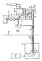
- the blasting system shown in Fig. 1 contains a large part of conventional components. These conventional components include a compressor 1, which feeds the compressed air supply line 4 via a water separator 2 and an air filter 3.
- a pressure measuring point 5 Between the compressor 1 and the water separator 2 there is a pressure measuring point 5 and a shut-off valve 6.
- the blasting agent container 20 containing the blasting agent with a closable refill opening 21, a line 22 which pressurizes the blasting agent container and is provided with a control valve, which leads to the Supply line 4 is connected and also a pressure relief valve 23.
- the refill opening 21 When the refill opening 21 is open, the blasting agent to be used for cleaning, preserving or coating can be refilled from a storage container 24 via a feed line 25 or a funnel.
- the blasting agent container 20 contains quartz sand, corundum, copper slag, natural or artificial mineral granules, cork or the like.
- such blasting agents can also be used for the intended underwater use with only one use of the blasting agent which, because of the danger to the respiratory tract of the worker operating the device, may no longer be used or may only be used under special protective conditions.
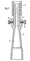
- a nozzle attachment 12 is connected to the Laval nozzle 9.
- a sleeve 10 which overlaps the free end of the nozzle and is held releasably and interchangeably with screws 11 is used to fasten the nozzle attachment 12.
- the funnel-shaped nozzle attachment 12 encloses an elongated paraboloid-shaped interior and has a length which corresponds essentially to the required working distance between the Laval nozzle 9 and the surface 50 to be treated. This length is z. B. for a nozzle attachment with 50 mm outlet diameter about 250 mm.
- a shunt control 30 is provided according to the invention.
- This shunt control 30 is connected on the inlet side via a line 31 to the outlet of the air filter 3 and on the outlet side via a control valve 32 to a part of the supply line 4 located downstream of the blasting agent container.
- the line system 31 -30-32 thus bridges the part of the supply line 4 in which the blasting agent is fed into the supply line 4 via a discharge valve 26.
- the compressed gas - preferably air - discharged into the blasting hose 8 via the shunt must have a pressure which is slightly above the water pressure at the place of use 41.
- a control line 36 leads from the shunt 30 to the underwater work station.
- the pressure detected in the bypass 30 at a pressure measuring point 38 directly influences a control valve 35 of the bypass and adjusts it so that small amounts of compressed air are constantly emitted at the jet nozzle attachment 12.
- additional pressure gauges 33 and 34 can be provided in the shunt control arranged above water in order to be able to read the normal working pressure and the pressure reduced in the shunt.
- the blasting device can be switched on and off in the simplest possible manner by the diver at the underwater work station 41, there is a button 51 next to the blasting nozzle 9, with which a control unit 53 located above water can be actuated via a signal line 52.
- the control unit 53 is used to switch on the blasting agent supply, i.e. the control unit 53 acts directly on the metering valve 26 of the blasting agent container 20 or, if this is permanently set, on the main shut-off valve 7 of the compressed air supply line 4. It is also possible to act on the shunt 30 with the control unit 53. As a rule, however, the shunt will be left open so that water cannot penetrate at the blasting nozzle attachment when the blasting agent addition is switched on and off.
- the device according to the invention leads to a safe and economical above- and underwater working method for standard-compliant surface treatment with a high degree of purity and required roughness depth while at the same time significantly increasing the area coverage and reducing the abrasive consumption.
Abstract
Description
Die Erfindung betrifft eine Vorrichtung zur auch unter Wasser durchführbaren Oberflächenbehandlung von Bauwerken und Schiffen mit einem reinigenden, konservierenden oder beschichtenden Strahlmittel, welches mit einem Druckgasstrom über eine zum Arbeitsplatzfürende, mitAustrittsdüse versehene, mindestens teilweise flexible Leitung auf die zu behandelnde Oberfläche aufgestrahlt wird, wobei die Austriffsdüse als Laval-Düse ausgebildet ist.The invention relates to a device for the surface treatment of structures and ships, which can also be carried out under water, with a cleaning, preserving or coating blasting agent which is blasted onto the surface to be treated with a compressed gas stream via an at least partially flexible line provided to the work station, with an outlet nozzle, the Discharge nozzle is designed as a Laval nozzle.
Das Druckluftstrahlen als Freistrahlen ist ein bewährtes Verfahren für Oberflächenbehandlung des Strahlgutes. Das Verfahren benötigt einen Kompressor als Druckluftquelle, einen Drucklufttrockner, einen Druckluftfilter, einen Strahlmittelbehälter zur Zudosierung des Strahlmittels und eine Schlauchleitung mit einer Düse, bei der es sich üblicherweise um eine Laval-Düse handelt. Die Leistung des Verfahrens wird bestimmt durch das Parameterfeld Luft Liefermenge des Kompressors in Abhängigkeit vom erforderlichen Enddruck, Strahlmitteldurchsatz, Schlauchlänge, Druck vor der Düse und Düsengrösse.Compressed air blasting as free blasting is a proven method for surface treatment of the blasting material. The method requires a compressor as a compressed air source, a compressed air dryer, a compressed air filter, a blasting agent container for metering in the blasting agent and a hose line with a nozzle, which is usually a Laval nozzle. The performance of the process is determined by the parameter field air delivery quantity of the compressor depending on the required final pressure, abrasive throughput, hose length, pressure in front of the nozzle and nozzle size.
Wenn es sich um das Reinigen und Aufrauhen von Oberflächen mit nur einmaliger Verwendung des Strahlmittels handelt, liegen typische Arbeitswerte unter normalen Bedingungen bei: 8 mm Düsen-Durchmesser, 250 mm Abstand von der Oberfläche des Strahlgutes und 80 mm Strahlfleckdurchmesser, entsprechend etwa 5000 mm2 Strahlfläche. Der Strahlmitteldurchsatz ist von der geforderten Oberflächengüte abhängig. Verständlicherweise wird für das Reinigen weniger Strahlmittel benötigt als zur Erzielung einer metallisch blanken Oberfläche mit bestimmter Rauhtiefe.When it comes to cleaning and roughening surfaces with a single use of the abrasive, typical working values under normal conditions are: 8 mm nozzle diameter, 250 mm distance from the surface of the blasting material and 80 mm blasting spot diameter, corresponding to about 5000 mm 2 Beam area. The abrasive throughput depends on the required surface quality. Understandably, less blasting media is required for cleaning than to achieve a bare metal surface with a certain roughness depth.
Erfahrungen der Erfinder haben gezeigt, dass die Effektivität bzw. die Arbeitsfähigkeit des Strahlmittelstromes auf dem Weg zwischen Düsenaustritt und zu bearbeitender Fläche sehr stark abnimmt, da die Überschallströmungsgeschwindigkeitsehrschnell zum Unterschallbereich abgebaut wird. Der theoretisch günstigste Arbeitsabstand von Null ist in der Praxis nicht realisierbar, da der Strahlfleck eine kritische kleine Fläche nicht unterschreiten darf. Dies entspricht aber einem Arbeitsabstand, über dessen Länge die unerwünschte Strahlgeschwindigkeitsverminderung bereits auftritt.Experience of the inventors has shown that the effectiveness or the workability of the abrasive stream on the path between the nozzle outlet and the surface to be processed decreases very greatly, since the supersonic flow velocity is reduced very quickly to the subsonic area. The theoretically most favorable working distance of zero cannot be achieved in practice because the beam spot must not be less than a critical small area. However, this corresponds to a working distance, over the length of which the undesired reduction in jet speed already occurs.
Der vorstehende Nachteil tritt verstärkt auch beim Arbeiten im oder unter Wasser auf. Hinzu kommen noch weitere Nachteile wie folgt:
- 1. Das Strahlmittel tritt nach der Beschleunigung in der Laval-Düse in ein Medium mitvielfach höherer Dichte ein. Dadurch verliert das beschleunigte Strahlmittel in verstärktem Masse an Geschwindigkeit, so dass es beim Auftreffen auf die zu bearbeitende Oberfläche kaum Wirkung zeigt, wenn zwischen Düsenaustritt und zu bearbeitender Oberfläche ein Wasserspalt vorhanden ist.
- 2. Eine Arbeitsverrichtung ist nur möglich durch Schrägansetzen der Laval-Düse unmittelbar auf die Oberfläche; damit wird der Strahlfleckdurchmesser gleich dem Düsenaustrittsdurchmesser. Für eine 8-mm-Düse beträgt die Strahlfläche unter Wasser nur etwa 50 mm2 und es kann eine definierte Oberflächengüte mit bestimmter Rauhtiefe unter diesen Bedingungen nicht erzielt werden.
- 3. In der Laval-Düse tritt ein proportional zur Einsatztiefe zunehmender Gegendruck auf.
- 1. After the acceleration in the Laval nozzle, the abrasive enters a medium with a much higher density. As a result, the accelerated blasting medium loses speed to an increased extent, so that it has little effect when it hits the surface to be processed if there is a water gap between the nozzle outlet and the surface to be processed.
- 2. Work can only be carried out by placing the Laval nozzle diagonally on the surface; the jet spot diameter thus becomes equal to the nozzle outlet diameter. For an 8 mm nozzle, the jet area under water is only about 50 mm2 and a defined surface quality with a certain roughness depth cannot be achieved under these conditions.
- 3. In the Laval nozzle, a back pressure increases proportionally to the depth of use.
Die vorstehenden Nachteile ergeben sich nicht nur bei einer Oberflächenbehandlung mit einem reinigenden Strahlmittel, sondern auch bei Oberflächenbehandlungen mit konservierenden oder beschichtenden StrahlmitteIn.The above disadvantages arise not only in the case of a surface treatment with a cleaning abrasive, but also in the case of surface treatments with a preserving or coating abrasive.
Aufgabe der Erfindung ist die Schaffung einer verbesserten Vorrichtung, die ausgehend von dem vorstehend geschilderten Stand der Technik die Möglichkeitgibt, solche Strahlverfahren mit höherem Wirkungsgrad zur Anwendung zu bringen.The object of the invention is to provide an improved device which, based on the above-described prior art, makes it possible to use such blasting processes with higher efficiency.
Diese Aufgabe wird erfindungsgemäss dadurch gelöst, dass die Austrittsdüse mit einem trichterförmigen, einen langgestreckten paraboloidförmigen Innenraum umschliessenden Düsenansatz versehen ist.This object is achieved according to the invention in that the outlet nozzle is provided with a funnel-shaped nozzle attachment which encloses an elongated paraboloid-shaped interior.
Die Erprobungen der erfindungsgemässen Vorrichtung zeigen eine offenbar durch erhöhte Strahlgeschwindigkeit bedingte, erheblich höhere Effektivität.The tests of the device according to the invention show a significantly higher effectiveness, apparently due to increased jet speed.
Gemäss einer Weiterbildung der Erfindung für den Unterwassereinsatz wird erfindungsgemäss vorgeschlagen, zwischen der Druckgasquelle und der zur Austrittsdüse und damit zu behandelnden Oberfläche führenden Leitung einen zusätzlichen, die Strahlmittelquelle umgehenden regelbaren Nebenschluss für das Druckgas vorzusehen.According to a further development of the invention for underwater use, it is proposed according to the invention to provide an additional, controllable shunt for the compressed gas, which bypasses the blasting agent source, between the compressed gas source and the line leading to the outlet nozzle and thus the surface to be treated.
Der erfindungsgemäss vorgesehene Nebenschluss lässt sich so regeln, dass auch in den Zeiten ohne Strahlmittelzufuhr die zum Unterwasserarbeitsplatz führende Leitung und die Düse trokken und frei von Wasser gehalten werden kann. Für das über den Nebenschluss geleitete Druckgas genügt ein relativ geringer Überdruck, welcher sicherstellt, dass am freien Ende der Austrittsdüse jederzeit das Druckgas ausperlt und hierdurch den Wassereintritt verhindert.The shunt provided according to the invention can be regulated in such a way that the line leading to the underwater work station and the nozzle can be kept dry and free of water even in times without blasting agent supply. A relatively low overpressure is sufficient for the compressed gas passed through the shunt, which ensures that the compressed gas bubbles out at all times at the free end of the outlet nozzle and thereby prevents water from entering.
Weitere Einzelheiten der Erfindung ergeben sich aus den Unteransprüchen.Further details of the invention emerge from the subclaims.
Nachfolgend wird eine für den Untetwassereinsatz bevorzugte Ausführungsform der Erfindung anhand der beigefügten Zeichnungen beispielsweise erläutert.In the following, an embodiment of the invention preferred for the use of underwater water is explained, for example, with reference to the attached drawings.
In den Zeichnungen zeigen:
- Fig. 1 eine schematische Darstellung der über und unter der Wasserfläche befindlichen Bauelemente der erfindungsgemässen Vorrichtung zur Oberflächenbehandlung, und
- Fig. 2 einen axialen Schnitt durch die Strahlmittelaustrittsdüse mit erfindungsgemässem Düsenansatz.
- Fig. 1 is a schematic representation of the components located above and below the water surface of the inventive device for surface treatment, and
- 2 shows an axial section through the blasting agent outlet nozzle with the nozzle attachment according to the invention.
Die in Fig. 1 dargestellte Strahlanlage enthält einen grossen Teil konventioneller Bauelemente. Zu diesen konventionellen Bauelementen gehört ein Kompressor 1, welcher über einen Wasserabscheider 2 und ein Luftfilter 3 die Druckluftversorgungsleitung 4 speist.The blasting system shown in Fig. 1 contains a large part of conventional components. These conventional components include a
Zwischen dem Kompressor 1 und dem Wasserabscheider 2 befinden sich eine Druckmessstelle 5 und ein Absperrventil 6. Konventionell ist auch der das Strahlmittel enthaltende Strahlmittelbehälter 20 mit einer verschliessbaren Nachfüllöffnung 21, eine den Strahlmittelbehälter unter Druck setzende und mit einem Regelventil versehene Leitung 22, die an die Versorgungsleitung 4 angeschlossen ist und ferner ein Überdruckventil 23. Bei geöffneter Nachfüllöffnung 21 kann über eine Zuführleitung 25 oder einem Trichter aus einem Vorratsbehälter 24 das zu verwendende Strahlmittel zum Reinigen, Konservieren oder Beschichten nachgefüllt werden.Between the
Wenn mit der erfindungsgemässen Vorrichtung Unterwasserreinigungen durchgeführt werden sollen, enthält der Strahlmittelbehälter 20 Quarzsand, Korund, Kupferschlacke, natürliche oder künstliche Mineralgranulate, Kork od. dgl. Für den vorgesehenen Unterwassereinsatz mit nur einmaliger Verwendung des Strahlmittels lassen sich anders als beim Freiluftstrahlen auch solche Strahlmittel einsetzen, die seit kurzem wegen der Gefährdung der Atemwege des die Vorrichtung bedienenden Arbeiters nicht mehr oder nur unter besonderen Schutzbedingungen verwendet werden dürfen.If underwater cleaning is to be carried out with the device according to the invention, the
Weiterhin konventionell ist die Verbindung der Druckluftversorgung 4 mit einem zum Arbeitsplatz führenden Strahlschlauch 8, welcher an einer, vorzugsweise als Laval-Düse ausgebildeten Austrittsdüse 9, endet.Also conventional is the connection of the compressed air supply 4 to a
Für den erfindungsgemäss vorgesehenen Unterwassereinsatz, bei dem der Strahlschlauch 8 unter die Wasseroberfläche 40 zu einem Unterwasserarbeitsplatz 41 führt, an dem sich ein Taucher 42 befindet, ist, wie Fig. 2 zeigt, an die Laval-Düse 9 ein Düsenansatz 12 angeschlossen. Zur Befestigung des Düsenansatzes 12 dient eine das freie Düsenende übergreifende Muffe 10, die mit Schrauben 11 lösbar und auswechselbar gehalten wird. Der trichterförmig ausgebildete Düsenansatz 12 umschliesst einen langgestreckten paraboloidförmigen Innenraum und hat eine Länge, die im wesentlichen dem erforderlichen Arbeitsabstand zwischen Laval-Düse 9 und der zu behandelnden Oberfläche 50 entspricht. Diese Länge beträgt z. B. für einen Düsenansatz mit 50 mm Austrittsdurchmesser etwa 250 mm.For the underwater use provided according to the invention, in which the
Um sicherzustellen, dass die unterwasserliegenden Vorrichtungsteile, das sind der Strahlschlauch 8, die Strahldüse 9 und der Strahldüsenansatz 12, ständig trocken bleiben und nicht voll Wasser laufen können, ist erfindungsgemäss eine Nebenschlussregelung 30 vorgesehen. Diese Nebenschlussregelung 30 ist eintrittsseitig über eine Leitung 31 an den Ausgang des Luftfilters 3 und austrittsseitig über ein Regelventil 32 mit einem in Strömungsrichtung hinter dem Strahlmittelbehälter liegenden Teil der Versorgungsleitung 4 verbunden. Das Leitungssystem 31 -30-32 überbrückt somit den Teil der Versorgungsleitung 4, in dem über ein Abgabeventil 26 das Strahlmittel in die Versorgungsleitung 4 eingegeben wird.In order to ensure that the underwater device parts, ie the
Bei nicht abgesperrtem Strahlmittelbehälter besteht somit die Möglichkeit, die unterwasserliegenden Bauelemente der Vorrichtung ständig mit einem Druckgasstrom zu durchspülen, so dass kein Wasser eindringen kann. Das über den Nebenschluss in den Strahlschlauch 8 abgegebene Druckgas - vorzugsweise Luft - muss einen Druck haben, der geringfügig über dem am Einsatzort 41 befindlichen Wasserdruck liegt. Um diese Druckeinstellung automatisch zu bewirken, führt vom Nebenschluss 30 eine Steuerleitung 36 zum Unterwasserarbeitsplatz. Der im Nebenschluss 30 an einer Druckmessstelle 38 erfasste Druck beeinflusst unmittelbar ein Regelventil 35 des Nebenschlusses und stellt dieses so ein, dass am Strahldüsenansatz 12 ständig in geringen Mengen Druckluft abgegeben wird. In der über Wasser angeordneten Nebenschlussregelung können, wie Fig. 1 zeigt, zusätzliche Druckmesser 33 und 34 vorgesehen sein, um den normalen Arbeitsdruck und den im Nebenschluss reduzierten Druck ablesen zu können.If the blasting agent container is not shut off, there is thus the possibility of constantly flushing the underwater components of the device with a pressurized gas stream, so that no water can penetrate. The compressed gas - preferably air - discharged into the
Damit am Unterwasserarbeitsptatz 41 vom Taucher die Strahlvorrichtung in möglichst einfacher Weise ein- und ausschaltbar ist, befindet sich neben der Strahldüse 9 ein Taster 51, mit dem über eine Signalleitung 52 ein über Wasser befindliches Steueraggregat 53 betätigt werden kann. Das Steueraggregat 53 dient zum Einschalten der Strahlmittelzufuhr, d.h. das Steueraggregat 53 wirkt unmittelbar auf das Zudosierventil 26 des Strahlmittelbehälters 20 oder, sofern dieses fest eingestellt ist, auf das Hauptabsperrventil 7 der Druckluftversorgungsleitung 4 ein. Möglich ist es ebenfalls, mit dem Steueraggregat 53 auf den Nebenschluss 30 einzuwirken. In der Regel wird man jedoch den Nebenschluss geöffnet lassen, so dass es beim Ein- und Ausschalten der Strahlmittelzugabe nicht zu einem Wassereinbruch am Strahldüsenansatz kommen kann.So that the blasting device can be switched on and off in the simplest possible manner by the diver at the
Sowohl beim Überwasser- als auch beim Unterwasserbetrieb ergaben sich erheblich verkürzte Arbeitszeiten und verbesserte Oberflächengüten. Bei Unterwasserbetrieb wurden beispielsweise in Verbindung mit dem erfindungsgemässen Druckluftnebenschluss und dem Düsenansatz 12 in 10 m Wassertiefe folgende Leistungsdaten erreicht: Strahlfläche ca. 2200 mm2, bei einem Gasdruck von etwa 9 bar Strahlleistung: 3 m2/h bei einem Reinheitsgrad Sa 2 1/2 (gemäss DIN 55 928 Teil 4) und einer Rauhtiefe von 30 11m.Both above-water and underwater operation resulted in significantly shorter working hours and improved surface qualities. In the case of underwater operation, for example in connection with the compressed air bypass according to the invention and the
Insgesamt ist somit festzustellen, dass die erfindungsgemässe Vorrichtung zu einem sicheren und wirtschaftlichen Über- und Unterwasserarbeitsverfahren zur normgerechten Oberflächenbehandlung mit hohem Reinheitsgrad und erforderlicher Rauhtiefe bei gleichzeitiger wesentlicher Steigerung der Flächenleistung und Senkung des Strahlmittelverbrauchs führt.Overall, it can thus be ascertained that the device according to the invention leads to a safe and economical above- and underwater working method for standard-compliant surface treatment with a high degree of purity and required roughness depth while at the same time significantly increasing the area coverage and reducing the abrasive consumption.
Claims (5)
Priority Applications (1)
| Application Number | Priority Date | Filing Date | Title |
|---|---|---|---|
| AT82102621T ATE11233T1 (en) | 1981-04-01 | 1982-03-29 | DEVICE FOR SURFACE TREATMENT OF STRUCTURES AND SHIPS. |
Applications Claiming Priority (2)
| Application Number | Priority Date | Filing Date | Title |
|---|---|---|---|
| DE3113028 | 1981-04-01 | ||
| DE3113028A DE3113028C2 (en) | 1981-04-01 | 1981-04-01 | Device for the surface treatment of underwater structures and ships |
Publications (2)
| Publication Number | Publication Date |
|---|---|
| EP0061756A1 EP0061756A1 (en) | 1982-10-06 |
| EP0061756B1 true EP0061756B1 (en) | 1985-01-16 |
Family
ID=6128991
Family Applications (1)
| Application Number | Title | Priority Date | Filing Date |
|---|---|---|---|
| EP82102621A Expired EP0061756B1 (en) | 1981-04-01 | 1982-03-29 | Apparatus for the surface-treatment of buildings and ships |
Country Status (9)
| Country | Link |
|---|---|
| US (1) | US4545317A (en) |
| EP (1) | EP0061756B1 (en) |
| JP (1) | JPS58500438A (en) |
| AT (1) | ATE11233T1 (en) |
| CA (1) | CA1182632A (en) |
| DE (2) | DE3113028C2 (en) |
| DK (1) | DK149425C (en) |
| ES (1) | ES8303217A1 (en) |
| WO (1) | WO1982003346A1 (en) |
Families Citing this family (26)
| Publication number | Priority date | Publication date | Assignee | Title |
|---|---|---|---|---|
| US5200230A (en) * | 1987-06-29 | 1993-04-06 | Dunfries Investments Limited | Laser coating process |
| AU622841B2 (en) * | 1988-03-02 | 1992-04-16 | Cleaning Technology Limited | Abrasive cleaning or cutting |
| US4830280A (en) * | 1988-03-21 | 1989-05-16 | Yankoff Gerald K | Nozzle |
| US5484325A (en) * | 1993-10-07 | 1996-01-16 | Church & Dwight Co., Inc. | Blast nozzle containing water atomizer for dust control |
| FR2723020B1 (en) * | 1994-07-26 | 1996-09-27 | Kegler Maurice | REMOTE CONTROL SANDING MACHINE |
| DE4430133C2 (en) * | 1994-08-25 | 1996-08-29 | Hubert Busch | Blasting kettle for applying an abrasive |
| US5647201A (en) * | 1995-08-02 | 1997-07-15 | Trw Inc. | Cavitating venturi for low reynolds number flows |
| WO1998006514A1 (en) * | 1996-08-09 | 1998-02-19 | Alfred Kärcher GmbH & Co. | High-pressure cleaning device |
| JPH1112721A (en) * | 1997-06-25 | 1999-01-19 | Sony Corp | Gas introducing pipe and production of magnetic recording medium with using same |
| AU3657497A (en) * | 1997-07-11 | 1999-02-08 | Waterjet International, Inc. | Method and apparatus for producing a high-velocity particle stream |
| BR9811100A (en) | 1997-07-11 | 2002-01-15 | Waterjet Technology Inc | Method and apparatus for producing a high-speed particle stream |
| US6168503B1 (en) | 1997-07-11 | 2001-01-02 | Waterjet Technology, Inc. | Method and apparatus for producing a high-velocity particle stream |
| RU2123957C1 (en) * | 1998-06-18 | 1998-12-27 | Макитрук Александр Александрович | Method of underwater hydrodynamic cleaning of ship's hull and device for realization of this method |
| FR2783735B1 (en) * | 1998-09-29 | 2000-12-15 | Patrick Loubeyre | DEVICE FOR THE DECONTAMINATION OF SURFACES BY MEANS OF A JET COMPOSED OF AIR, A FINE-GRAINED SPRAYING MATERIAL AND A LIQUID |
| US6350185B1 (en) * | 2000-02-09 | 2002-02-26 | Space Systems/Loral, Inc. | Grit blast nozzle for surface preparation of tube |
| RU2163877C1 (en) * | 2000-07-12 | 2001-03-10 | Игнатьев Александр Викторович | Tool for underwater cleaning of surfaces and nozzle for this tool |
| GB2372718B (en) * | 2001-01-04 | 2004-07-14 | Workinter Ltd | Nozzle intended for the concentrated distribution of a fluid for scouring of surfaces |
| US6626738B1 (en) * | 2002-05-28 | 2003-09-30 | Shank Manufacturing | Performance fan nozzle |
| US20030236489A1 (en) | 2002-06-21 | 2003-12-25 | Baxter International, Inc. | Method and apparatus for closed-loop flow control system |
| US20140263693A1 (en) * | 2011-11-18 | 2014-09-18 | Arizona Board Of Regents, A Body Corporate Of The State Of Arizona, Acting For And On Behalf | System and method for providing a micron-scale continuous liquid jet |
| US10086497B1 (en) * | 2012-04-27 | 2018-10-02 | Chukar Waterjet, Inc. | Submersible liquid jet apparatus |
| US9132529B2 (en) * | 2012-12-07 | 2015-09-15 | United Technologies Corporation | Media blast nozzle with non-metallic threads |
| KR101305256B1 (en) * | 2012-12-18 | 2013-09-06 | 포항공과대학교 산학협력단 | A nozzle to generate superspeed uniform nano paticles and a device and method thereof |
| US10081091B2 (en) * | 2015-06-12 | 2018-09-25 | Postech Academy-Industry Foundation | Nozzle, device, and method for high-speed generation of uniform nanoparticles |
| CN113042295B (en) * | 2021-03-18 | 2022-12-06 | 中建三局绿色产业投资有限公司 | Water conservancy is touch-up paint equipment under water |
| EP4205905A1 (en) * | 2021-12-30 | 2023-07-05 | SR Robotics Sp. z.o.o. | Underwater, remote-controlled high pressure cutting device with addition of abrasive material, and cutting and abrasive material feeding method |
Family Cites Families (13)
| Publication number | Priority date | Publication date | Assignee | Title |
|---|---|---|---|---|
| FR960172A (en) * | 1950-04-14 | |||
| GB392826A (en) * | 1932-10-25 | 1933-05-25 | Ronald Alfred Gilbert | Improvements in or relating to blasting nozzles for surface treating plant |
| US2583726A (en) * | 1948-01-26 | 1952-01-29 | Chalom Joseph Aaron | Nozzle |
| US2666279A (en) * | 1949-01-17 | 1954-01-19 | Chalom Joseph Aron | Nozzle for expansion and compression of gases |
| US3070924A (en) * | 1958-02-04 | 1963-01-01 | Hastrup Herman | Remote control system for fluid actuated mechanism |
| US3256642A (en) * | 1963-11-07 | 1966-06-21 | Rocco P Fonti | Underwater sandblasting gun |
| US3323257A (en) * | 1964-08-20 | 1967-06-06 | Rocco P Fonti | Systems for underwater sandblasting |
| JPS4411597Y1 (en) * | 1965-09-30 | 1969-05-14 | ||
| DE1804860A1 (en) * | 1968-10-24 | 1970-05-06 | Paul Hammelmann | Press water operated, self-adhesive cleaning device as well as method for surface cleaning |
| DE2450510A1 (en) * | 1974-10-24 | 1976-04-29 | Woma Maasberg Co Gmbh W | DEVICE FOR TREATMENT OF SURFACES |
| JPS5310023A (en) * | 1976-07-14 | 1978-01-30 | Honda Motor Co Ltd | Ac generator |
| US4209952A (en) * | 1977-09-12 | 1980-07-01 | F. A. Hughes And Company Limited | Underwater jet blasting apparatus |
| DE2848436C2 (en) * | 1978-11-08 | 1982-05-06 | Paul 4740 Oelde Hammelmann | Device for cleaning the bottom of a ship when docking a ship |
-
1981
- 1981-04-01 DE DE3113028A patent/DE3113028C2/en not_active Expired
-
1982
- 1982-03-29 DE DE8282102621T patent/DE3261903D1/en not_active Expired
- 1982-03-29 US US06/445,498 patent/US4545317A/en not_active Expired - Fee Related
- 1982-03-29 AT AT82102621T patent/ATE11233T1/en not_active IP Right Cessation
- 1982-03-29 EP EP82102621A patent/EP0061756B1/en not_active Expired
- 1982-03-29 JP JP57501081A patent/JPS58500438A/en active Pending
- 1982-03-29 WO PCT/DE1982/000070 patent/WO1982003346A1/en unknown
- 1982-03-30 CA CA000399770A patent/CA1182632A/en not_active Expired
- 1982-03-31 ES ES511025A patent/ES8303217A1/en not_active Expired
- 1982-09-27 DK DK427382A patent/DK149425C/en not_active IP Right Cessation
Also Published As
| Publication number | Publication date |
|---|---|
| ATE11233T1 (en) | 1985-02-15 |
| DK427382A (en) | 1982-10-14 |
| DE3113028A1 (en) | 1982-10-28 |
| US4545317A (en) | 1985-10-08 |
| DE3113028C2 (en) | 1983-10-13 |
| JPS58500438A (en) | 1983-03-24 |
| EP0061756A1 (en) | 1982-10-06 |
| DE3261903D1 (en) | 1985-02-28 |
| ES511025A0 (en) | 1983-02-01 |
| DK149425B (en) | 1986-06-09 |
| DK149425C (en) | 1986-11-17 |
| WO1982003346A1 (en) | 1982-10-14 |
| CA1182632A (en) | 1985-02-19 |
| ES8303217A1 (en) | 1983-02-01 |
Similar Documents
| Publication | Publication Date | Title |
|---|---|---|
| EP0061756B1 (en) | Apparatus for the surface-treatment of buildings and ships | |
| EP0171448B1 (en) | Device and method for cleaning of stone and metal surfaces | |
| EP0468024B1 (en) | Injection device for on-line wet cleaning of compressors | |
| EP0582191B1 (en) | Apparatus and method for the treatment of sensitive surfaces, especially sculptures | |
| EP0634229A1 (en) | Method, assembly and apparatus for internal cleaning and coating of pipelines | |
| DE2724318A1 (en) | Sand blasting equipment using additives - has tanks for blasting medium and additive with separate connections to blasting nozzle | |
| EP2151300A1 (en) | Device and method for cleaning objects using dry snow | |
| DE1809677A1 (en) | Jet nozzle for high pressure jet devices | |
| DE3527923C2 (en) | ||
| WO2018184798A1 (en) | Device and method for a high-pressure fluid jet cutting process | |
| DE102004023246B3 (en) | Spraying method for jet spraying of surfaces with water-soluble medium entails feeding by carrier gas spraying medium to spray nozzle and metering water into carrier gas flow | |
| DE2253633A1 (en) | DEVICE FOR SPRAYING POWDER | |
| EP2785494B1 (en) | Method for wet-blasting workpieces | |
| DE3204861A1 (en) | Method and device for cleaning facades or the like | |
| WO1985004614A1 (en) | Process and apparatus for subjecting workpieces, construction elements or similar to an air jet laden with granular particles | |
| DE4209353C2 (en) | Wet blasting system with a blasting gun | |
| WO2003022525A2 (en) | Blasting method and device | |
| DE4127886A1 (en) | Nozzle head for high pressure sand blaster plant - has housing block with blasting material supply, and concentric pressurised water supply | |
| DE4201860C1 (en) | ||
| DE802430C (en) | Method and device for sanding objects | |
| EP0069875B1 (en) | Abrasive blasting method using air under pressure, and device therefor | |
| DE8109719U1 (en) | DEVICE FOR SURFACE TREATMENT OF UNDERWATER CONSTRUCTIONS AND SHIPS | |
| DE3744598C1 (en) | Method and device for removing blockages in a conveyor line | |
| DE19738572A1 (en) | Metering valve with housing, through-hole and membrane | |
| DE102014114868A1 (en) | Apparatus and method for blasting a cleaning medium on a surface to be cleaned |
Legal Events
| Date | Code | Title | Description |
|---|---|---|---|
| PUAI | Public reference made under article 153(3) epc to a published international application that has entered the european phase |
Free format text: ORIGINAL CODE: 0009012 |
|
| AK | Designated contracting states |
Designated state(s): AT BE CH DE FR GB IT LU NL SE |
|
| 17P | Request for examination filed |
Effective date: 19821105 |
|
| ITF | It: translation for a ep patent filed |
Owner name: UFFICIO BREVETTI VARESINO |
|
| GRAA | (expected) grant |
Free format text: ORIGINAL CODE: 0009210 |
|
| AK | Designated contracting states |
Designated state(s): AT BE CH DE FR GB IT LI LU NL SE |
|
| REF | Corresponds to: |
Ref document number: 11233 Country of ref document: AT Date of ref document: 19850215 Kind code of ref document: T |
|
| REF | Corresponds to: |
Ref document number: 3261903 Country of ref document: DE Date of ref document: 19850228 |
|
| PG25 | Lapsed in a contracting state [announced via postgrant information from national office to epo] |
Ref country code: LU Free format text: LAPSE BECAUSE OF NON-PAYMENT OF DUE FEES Effective date: 19850331 |
|
| ET | Fr: translation filed | ||
| PLBE | No opposition filed within time limit |
Free format text: ORIGINAL CODE: 0009261 |
|
| STAA | Information on the status of an ep patent application or granted ep patent |
Free format text: STATUS: NO OPPOSITION FILED WITHIN TIME LIMIT |
|
| 26N | No opposition filed | ||
| PGFP | Annual fee paid to national office [announced via postgrant information from national office to epo] |
Ref country code: LU Payment date: 19860115 Year of fee payment: 5 |
|
| PGFP | Annual fee paid to national office [announced via postgrant information from national office to epo] |
Ref country code: AT Payment date: 19870303 Year of fee payment: 6 |
|
| PGFP | Annual fee paid to national office [announced via postgrant information from national office to epo] |
Ref country code: NL Payment date: 19870331 Year of fee payment: 6 |
|
| PG25 | Lapsed in a contracting state [announced via postgrant information from national office to epo] |
Ref country code: AT Effective date: 19880329 |
|
| PG25 | Lapsed in a contracting state [announced via postgrant information from national office to epo] |
Ref country code: LI Effective date: 19880331 Ref country code: CH Effective date: 19880331 |
|
| BERE | Be: lapsed |
Owner name: H. LORENZ G.M.B.H. Effective date: 19880331 Owner name: GKSS-FORSCHUNGSZENTRUM GEESTHACHT G.M.B.H. Effective date: 19880331 |
|
| REG | Reference to a national code |
Ref country code: CH Ref legal event code: PL |
|
| PG25 | Lapsed in a contracting state [announced via postgrant information from national office to epo] |
Ref country code: GB Effective date: 19890329 |
|
| PG25 | Lapsed in a contracting state [announced via postgrant information from national office to epo] |
Ref country code: SE Effective date: 19890330 |
|
| PG25 | Lapsed in a contracting state [announced via postgrant information from national office to epo] |
Ref country code: BE Effective date: 19890331 |
|
| PG25 | Lapsed in a contracting state [announced via postgrant information from national office to epo] |
Ref country code: NL Effective date: 19891001 |
|
| NLV4 | Nl: lapsed or anulled due to non-payment of the annual fee | ||
| GBPC | Gb: european patent ceased through non-payment of renewal fee | ||
| PG25 | Lapsed in a contracting state [announced via postgrant information from national office to epo] |
Ref country code: FR Free format text: LAPSE BECAUSE OF NON-PAYMENT OF DUE FEES Effective date: 19891130 |
|
| REG | Reference to a national code |
Ref country code: FR Ref legal event code: ST |
|
| PGFP | Annual fee paid to national office [announced via postgrant information from national office to epo] |
Ref country code: DE Payment date: 19930528 Year of fee payment: 12 |
|
| PG25 | Lapsed in a contracting state [announced via postgrant information from national office to epo] |
Ref country code: DE Effective date: 19941201 |
|
| EUG | Se: european patent has lapsed |
Ref document number: 82102621.8 Effective date: 19900124 |