EP0061514A1 - Shelf with cantilever brackets - Google Patents
Shelf with cantilever brackets Download PDFInfo
- Publication number
- EP0061514A1 EP0061514A1 EP81107034A EP81107034A EP0061514A1 EP 0061514 A1 EP0061514 A1 EP 0061514A1 EP 81107034 A EP81107034 A EP 81107034A EP 81107034 A EP81107034 A EP 81107034A EP 0061514 A1 EP0061514 A1 EP 0061514A1
- Authority
- EP
- European Patent Office
- Prior art keywords
- cantilever
- profile
- rack according
- punched
- hooks
- Prior art date
- Legal status (The legal status is an assumption and is not a legal conclusion. Google has not performed a legal analysis and makes no representation as to the accuracy of the status listed.)
- Granted
Links
Images

Classifications
-
- A—HUMAN NECESSITIES
- A47—FURNITURE; DOMESTIC ARTICLES OR APPLIANCES; COFFEE MILLS; SPICE MILLS; SUCTION CLEANERS IN GENERAL
- A47B—TABLES; DESKS; OFFICE FURNITURE; CABINETS; DRAWERS; GENERAL DETAILS OF FURNITURE
- A47B57/00—Cabinets, racks or shelf units, characterised by features for adjusting shelves or partitions
- A47B57/30—Cabinets, racks or shelf units, characterised by features for adjusting shelves or partitions with means for adjusting the height of detachable shelf supports
- A47B57/40—Cabinets, racks or shelf units, characterised by features for adjusting shelves or partitions with means for adjusting the height of detachable shelf supports consisting of hooks coacting with openings
- A47B57/42—Cabinets, racks or shelf units, characterised by features for adjusting shelves or partitions with means for adjusting the height of detachable shelf supports consisting of hooks coacting with openings the shelf supports being cantilever brackets
Definitions
- the invention relates to a cantilever rack for long goods, such as boards, pipes, profiles and. Like., With T-profile stands and cantilevers extending from these.
- cantilever racks of this type there is a need to be able to adapt them in a simple manner to spatial conditions and to the goods to be stored, specifically in terms of their nature and dimensions. Furthermore, such shelves should be easier to assemble and disassemble.
- pairs of punched-out holes are arranged at a distance from one another, one above the other, and that the cantilever arms have hooks at one end with which they can be detached in a pair of punched-outs can be hung in the flanges of the T-profile stands.
- the stands can be arranged at any equal or unequal distances from one another, and the cantilevers can be attached in any number to the stands in a detachable manner, as required, desired height adjustments being possible without further ado.
- the cut-outs can be square or round.
- a particularly advantageous embodiment results when the hook is opposite the top of the cantilever extends upwards. This makes it very easy to unhook and mount.
- the profile stand and the cantilever arm can advantageously be double T profiles. A particularly stable construction is achieved in this way.
- pairs of punched-out sections can be formed in the two flanges of the double-T profile stand.
- a footplate can advantageously be attached to the end of the cantilever arm, the upper end of which supports the hooks.
- this footplate can be welded to the cantilever.
- the height of the footplate can be greater than the height of the cantilever.
- the front of the base plate can be connected to the underside of the cantilever arm by means of a support triangle. These parts can also be welded together.
- support feet can be attached to the lower end of the profile stand.
- the mutual spacing of the profile stands is ensured in that spacers are arranged between the profile stands. These can be screwed on. Between the profile stands can also be diagonal tension bandages can be arranged.
- This cantilever rack can be extended in blocks as required.
- the cantilever rack according to the invention has T-profile stand 1.
- Two stands are provided for at least one shelf.
- the number of stands is arbitrary, and these T-profile stands can be arranged at the same or different intervals. In the illustrated embodiment, these T-profile stands are double T-profile stands.
- Pairs of cutouts 3 are arranged in the flanges 2 of this profile stand 1.
- the punched-out portions 3 of each pair are at the same height, and the pairs are arranged one above the other in the flanges 2.
- These punched-out pairs 3 can be formed in one flange 2 or in both flanges of the double-T beam. These cut-outs can either be square or round.
- the cantilever arms 4 have hooks 5 at one end, with which they can be detachably mounted in each case: "A pair of punched-outs 3 in the flanges 2 of the profile stand 1 can be attached. It can be seen that any number of cantilever arms can be hooked into a stand in a simple manner by means of this design, specifically at predetermined and desired heights, and that height changes of the cantilever arms can optionally be carried out in a very simple manner.
- a foot plate 7 is attached to the end of the cantilever arm 2.
- This base plate 7 can, for example, be welded to the cantilever arm 4.
- a good support of the cantilever on the profile stand 1 is achieved in that the height H of the foot plate 7 is greater than the height h of the cantilever 4.
- the structure is designed so that the Distance D of the side 9 of the hook 5 resting against the inside 8 of the flange 2 from the side 18 of the foot plate 7 resting against the outside 10 of the flange 2 is substantially equal to the thickness dimension d of the flange. This avoids a lot of tolerances that could lead to an unstable structure.
- the front side 11 of the foot plate 7 is connected to the underside 12 of the cantilever arm 2 by means of a support triangle.
- a welded connection can also be provided here. In this way, the load transmission, in particular the transmission of moment loads, is improved.
- Support feet 14 are fastened to the lower end of the profile stand 1, and the connection can in turn be made by welding. However, a screw connection is also possible. This embodiment is particularly advantageous when no fixed installation is intended.
- Spacers 15 can be arranged between the profile stands 1, and these spacers can be screwed on. If a fixed installation is provided, a welded connection can also be provided.
Landscapes
- Assembled Shelves (AREA)
- Warehouses Or Storage Devices (AREA)
- Cabinets, Racks, Or The Like Of Rigid Construction (AREA)
- Rod-Shaped Construction Members (AREA)
Abstract
Description
Die Erfindung betrifft ein Kragarm-Regal für Langgutprodukte, wie Bretter, Rohre, Profileisen u. dgl., mit T-Profilständern und sich von diesen aus erstreckenden Kragarmen.The invention relates to a cantilever rack for long goods, such as boards, pipes, profiles and. Like., With T-profile stands and cantilevers extending from these.
Bei derartigen Kragarm-Regalen besteht das Bedürfnis, diese in einfacher Weise an räumliche Bedingungen und an die zu lagernden Güter, und zwar nach Beschaffenheit und Abmessung, in einfachster Weise anpassen zu können. Ferner sollten derartige Regale einfacher montiert und abgebaut werden können.With cantilever racks of this type, there is a need to be able to adapt them in a simple manner to spatial conditions and to the goods to be stored, specifically in terms of their nature and dimensions. Furthermore, such shelves should be easier to assemble and disassemble.
Erfindungsgemäß werden diese Probleme dadurch gelöst, daß in den Flanschen der T-Profilständer Paare von in gleicher Höhe liegender Ausstanzungen im Abstand voneinander, übereinander angeordnet sind und daß die Kragarme Haken an einem Ende tragen, mit denen sie in lösbarer Weise in je ein Paar Ausstanzungen in den Flanschen der T-Profilständer einhängbar sind. Die Ständer können in beliebigen gleichen oder ungleichen Abständen voneinander angeordnet werden, und die Kragarme können je nach Bedarf in beliebiger Anzahl an den Ständern in lösbarer Weise eingehängt werden, wobei gewünschte Höhenverstellungen ohne weiteres möglich sind. Die Ausstanzungen können vierkant oder rund gestanzt sein.According to the invention, these problems are solved in that in the flanges of the T-profile stands, pairs of punched-out holes are arranged at a distance from one another, one above the other, and that the cantilever arms have hooks at one end with which they can be detached in a pair of punched-outs can be hung in the flanges of the T-profile stands. The stands can be arranged at any equal or unequal distances from one another, and the cantilevers can be attached in any number to the stands in a detachable manner, as required, desired height adjustments being possible without further ado. The cut-outs can be square or round.
Eine besonders vorteilhafte Ausführungsform ergibt sich, wenn der Haken gegenüber der Oberseite des Kragarmes sich nach oben erstreckt. Hierdurch ist ein ganz einfaches Aushängen und Einhängen möglich.A particularly advantageous embodiment results when the hook is opposite the top of the cantilever extends upwards. This makes it very easy to unhook and mount.
Der Profilständer und der Kragarm können mit Vorteil Doppel-T-Profile sein. Hierdurch wird ein besonders stabiler Aufbau erzielt. Dabei können insbesondere Paare von Ausstanzungen in den beiden Flanschen des Doppel-T-Profilständers-ausgebildet sein.The profile stand and the cantilever arm can advantageously be double T profiles. A particularly stable construction is achieved in this way. In particular, pairs of punched-out sections can be formed in the two flanges of the double-T profile stand.
Um die Stabilität des Kragarm-Regals zu verbessern, kann mit Vorteil am Ende des Kragarms eine Fußplatte befestigt sein, deren oberes Ende die Haken trägt. Insbesondere kann diese Fußplatte am Kragarm angeschweißt sein. Um die Stabilität zu erhöhen, kann die Höhe der Fußplatte größer sein als die Höhe des Kragarmes.In order to improve the stability of the cantilever rack, a footplate can advantageously be attached to the end of the cantilever arm, the upper end of which supports the hooks. In particular, this footplate can be welded to the cantilever. To increase stability, the height of the footplate can be greater than the height of the cantilever.
Damit ein guter Sitz des Kragarmes am Profilständer erzielt wird, kann der Abstand der gegen die Innenseite des Flansches anliegenden Seite des Hakens von der gegen die . Außenseite des Flansches anliegenden Seite der Fußplatte im wesentlichen gleich der Dickenabmessung des Flansches sein.So that a good fit of the cantilever arm is achieved on the profile stand, the distance of the side of the hook against the inside of the flange from the against the. Outside of the flange adjacent side of the base plate be substantially equal to the thickness dimension of the flange.
Um die Stützverbindung zwischen dem Kragarm und der Fußplatte zu verbessern, kann die Vorderseite der Fußplatte mit der Unterseite des Kragarmes mittels eines Stützdreiecks verbunden sein. Auch diese Teile können miteinander verschweißt sein.In order to improve the support connection between the cantilever arm and the base plate, the front of the base plate can be connected to the underside of the cantilever arm by means of a support triangle. These parts can also be welded together.
Um die Standfestigkeit des Regals zu verbessern, können am unteren Ende der Profilständer Stützfüße befestigt sein. Der gegenseitige Abstand der Profilständer wird dadurch gesichert, daß zwischen den Profilständern Distanzstücke angeordnet sind. Diese können angeschraubt sein. Zwischen den Profilständern können ferner Diagonalspannverbände angeordnet sein.To improve the stability of the shelf, support feet can be attached to the lower end of the profile stand. The mutual spacing of the profile stands is ensured in that spacers are arranged between the profile stands. These can be screwed on. Between the profile stands can also be diagonal tension bandages can be arranged.
Dieses Kragarm-Regal kann in Blöcken beliebig verlängert werden.This cantilever rack can be extended in blocks as required.
Ein Ausführungsbeispiel der Erfindung soll in der folgenden Beschreibung unter Bezugnahme auf die Figuren der Zeichnung erläutert werden. Es zeigen
- Fig. 1 eine perspektivische Ansicht eines Kragarm-Regals
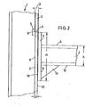
und - Fig. 2 eine schematische Ansicht eines Details des Regals.
- Fig. 1 is a perspective view of a cantilever rack
and - Fig. 2 is a schematic view of a detail of the shelf.
Das erfindungsgemäße Kragarm-Regal weist T-Profilständer 1 auf. Es sind zumindest für ein Regal zwei Ständer vorgesehen. Die Anzahl der Ständer ist beliebig, und diese T-Profilständer können in gleichen oder ungleichen Abständen angeordnet sein. Beim dargestellten Ausführungsbeispiel sind diese T-Profilständer Doppel-T-Profilständer.The cantilever rack according to the invention has T-profile stand 1. Two stands are provided for at least one shelf. The number of stands is arbitrary, and these T-profile stands can be arranged at the same or different intervals. In the illustrated embodiment, these T-profile stands are double T-profile stands.
In den Flanschen 2 dieser Profilständer 1 sind Paare von Ausstanzungen 3 angeordnet. Die Ausstanzungen 3 eines jeden Paares liegen in gleicher Höhe, und die Paare sind im Abstand voneinander übereinander in den Flanschen 2 angeordnet. Diese Ausstanzungspaare 3 können in einem Flansch 2 oder in beiden Flanschen des Doppel-T-Trägers ausgebildet sein. Diese Ausstanzungen können entweder vierkant oder rund gestanzt sein.Pairs of
Um nun in beliebiger Weise Regale gestalten, montieren und anpassen zu können, weisen die Kragarme 4 an einem Ende Haken 5 auf, mit denen sie in lösbarer Weise in je ei:" Paar Ausstanzungen 3 in den Flanschen 2 der Profilständer 1 einhängbar sind. Es ist zu erkennen, daß in einfacher Weise durch diese Ausbildung beliebig viel Kragarme in einen Ständer eingehängt werden können, und zwar in vorbestimmten und gewünschten Höhen, und daß gegebenenfalls in einfachster Weise Höhenveränderungen der Kragarme vorgenommen werden können.In order to be able to design, assemble and adapt shelves in any way, the cantilever arms 4 have
Ein besonders vorteilhafter Aufbeu ergibt sich, wenn sich die Haken 5 gegenüber der Oberseite 6 des Kragarmes 2 nach oben erstrecken. Das Ein- und Aushängen der Kragarme wird hierdurch erheblich erleichtert.A particularly advantageous Aufbeu results when the
Zur Erhöhung der Stabilität des Kragarm-Regals trägt es bei, wenn am Ende des Kragarmes 2 eine Fußplatte 7 befestigt wird. Diese Fußplatte 7 kann am Kragarm 4 beispielsweise angeschweißt sein. Eine gute Abstützung des Kragarmes am Profilständer 1 wird dadurch erzielt, daß die Höhe H der Fußplatte 7 größer ist als die Höhe h des Kragarmes 4. Um einen satten und guten Sitz des Kragarmes am Profilständer zu erzielen, wird der Aufbau so gestaltet, daß der Abstand D der gegen die Innenseite 8 des Flansches 2 anliegenden Seite 9 des Hakens 5 von der gegen die Außenseite 10 des Flansches 2 anliegenden Seite 18 der Fußplatte 7 im wesentlichen gleich der Dickenabmessung d des Flansches ist. Hierdurch werden viel Toleranzen vermieden, die zu einem unstabilen Aufbau führen könnten.To increase the stability of the cantilever rack, it helps if a
Um die Stützverbindung weiterhin zu verbessern, wird die Vorderseite 11 der Fußplatte 7 mit der Unterseite 12 des Kragarmes 2 mittels eines Stützdreieckes verbunden. Auch hier kann wiederum eine Schweißverbindung vorgesehen sein. Auf diese Weise wird die Belastungsübertragung, insbesondere die übertragung von Momentenlasten, verbessert.In order to further improve the support connection, the front side 11 of the
Am unteren Ende der Profilständer 1 sind Stützfüße 14 befestigt, wobei die Verbindung wiederum mittels Verschweißung erfolgen kann. Es ist aber auch eine Verschraubung möglich. Diese Ausführungsform ist insbesondere dann von Vorteil, wenn keine ortsfeste Aufstellung beabsichtigt ist.
Zwischen den Profilständern 1 können Distanzstücke 15 angeordnet werden, wobei diese Distanzstücke angeschraubt werden können. Falls eine ortsfeste Aufstellung vorgesehen ist, kann auch eine Schweißverbindung vorgesehen sein.
Zwischen den Profilständern 1 sind Diagonalspannverbände 16 angeordnet, die Spannschrauben 17 aufweisen.Between the profile stands 1,
Es ist zu erkennen, daß durch diese Ausbildung ein sehr stabiler Aufbau des Kragarm-Regals möglich ist, wobei sich dieses Regal mit geringem Arbeitsaufwand leicht verändern und entstehenden Forderungen anpassen läßt. Die Montage und die Demontage ist außerordentlich einfach und kann von ungeschultem Personal durchgeführt werden.It can be seen that a very stable construction of the cantilever rack is possible through this design, this rack can be easily changed with little work and adapt to the resulting requirements. The assembly and disassembly is extremely simple and can be carried out by untrained personnel.
Claims (11)
Priority Applications (1)
| Application Number | Priority Date | Filing Date | Title |
|---|---|---|---|
| AT81107034T ATE20304T1 (en) | 1981-03-24 | 1981-09-07 | CANTILE SHELF. |
Applications Claiming Priority (2)
| Application Number | Priority Date | Filing Date | Title |
|---|---|---|---|
| DE19818108652U DE8108652U1 (en) | 1981-03-24 | 1981-03-24 | CANTILEVER SHELF, HANGABLE VERSION |
| DE8108652U | 1981-03-24 |
Publications (2)
| Publication Number | Publication Date |
|---|---|
| EP0061514A1 true EP0061514A1 (en) | 1982-10-06 |
| EP0061514B1 EP0061514B1 (en) | 1986-06-11 |
Family
ID=6726023
Family Applications (1)
| Application Number | Title | Priority Date | Filing Date |
|---|---|---|---|
| EP81107034A Expired EP0061514B1 (en) | 1981-03-24 | 1981-09-07 | Shelf with cantilever brackets |
Country Status (3)
| Country | Link |
|---|---|
| EP (1) | EP0061514B1 (en) |
| AT (1) | ATE20304T1 (en) |
| DE (1) | DE8108652U1 (en) |
Cited By (4)
| Publication number | Priority date | Publication date | Assignee | Title |
|---|---|---|---|---|
| DE29622112U1 (en) * | 1996-12-19 | 1997-03-06 | Ohra Regalanlagen Gmbh | Cantilever rack |
| WO1998011804A1 (en) * | 1996-09-17 | 1998-03-26 | Ohra Regalanlagen Gmbh | Cantilever type shelf |
| DE20304146U1 (en) * | 2003-03-14 | 2004-07-29 | Ohra Regalanlagen Gmbh | Unit for transporting long items such as boards, tubes and iron shapes, has shelves formed from pillars and extending beams with tensioning belts on a truck trailer |
| WO2022123086A1 (en) | 2020-12-11 | 2022-06-16 | Hölscher Holding GmbH | Cantilever rack |
Families Citing this family (6)
| Publication number | Priority date | Publication date | Assignee | Title |
|---|---|---|---|---|
| DE3832537A1 (en) * | 1988-09-24 | 1990-03-29 | Hoelscher Ottokar | CANTILEVER SHELF |
| DE3937337A1 (en) * | 1989-11-09 | 1991-05-16 | Hoelscher Andreas Dipl Kaufm | CANTILEVER SHELF WITH CONNECTOR |
| DE9111364U1 (en) * | 1991-09-13 | 1991-11-14 | Intra-Profiel Staalbouwtechniek B.V., Velp, Nl | |
| DE9204949U1 (en) * | 1992-04-09 | 1992-06-04 | Ohra Regalanlagen Gmbh, 5014 Kerpen, De | |
| DE29915443U1 (en) | 1999-09-02 | 1999-11-25 | Hoelscher Andreas | Cantilever rack |
| IT201700058491A1 (en) | 2017-05-30 | 2018-11-30 | Granitifiandre Spa | METHOD FOR THE TRANSPORT AND STORAGE OF CERAMIC SLABS |
Citations (3)
| Publication number | Priority date | Publication date | Assignee | Title |
|---|---|---|---|---|
| GB710030A (en) * | 1952-04-10 | 1954-06-02 | Kenneth Eustace | Improvements in or relating to display brackets |
| US3485382A (en) * | 1967-09-15 | 1969-12-23 | Larson Co Charles O | Shelf support |
| US4023684A (en) * | 1975-09-08 | 1977-05-17 | Rack Engineering Company | Cantilever rack structure |
Family Cites Families (2)
| Publication number | Priority date | Publication date | Assignee | Title |
|---|---|---|---|---|
| DE1042211B (en) * | 1956-08-23 | 1958-10-30 | Windenfabrik Gottfried Schober | Hoist winch with height-adjustable claw |
| DE7711112U1 (en) * | 1977-04-07 | 1977-08-25 | Kaiser, Manfred, 3590 Bad Wildungen | HEAVY DUTY ARM SHELVING - SCREWLESS ADJUSTABLE |
-
1981
- 1981-03-24 DE DE19818108652U patent/DE8108652U1/en not_active Expired
- 1981-09-07 EP EP81107034A patent/EP0061514B1/en not_active Expired
- 1981-09-07 AT AT81107034T patent/ATE20304T1/en not_active IP Right Cessation
Patent Citations (3)
| Publication number | Priority date | Publication date | Assignee | Title |
|---|---|---|---|---|
| GB710030A (en) * | 1952-04-10 | 1954-06-02 | Kenneth Eustace | Improvements in or relating to display brackets |
| US3485382A (en) * | 1967-09-15 | 1969-12-23 | Larson Co Charles O | Shelf support |
| US4023684A (en) * | 1975-09-08 | 1977-05-17 | Rack Engineering Company | Cantilever rack structure |
Cited By (4)
| Publication number | Priority date | Publication date | Assignee | Title |
|---|---|---|---|---|
| WO1998011804A1 (en) * | 1996-09-17 | 1998-03-26 | Ohra Regalanlagen Gmbh | Cantilever type shelf |
| DE29622112U1 (en) * | 1996-12-19 | 1997-03-06 | Ohra Regalanlagen Gmbh | Cantilever rack |
| DE20304146U1 (en) * | 2003-03-14 | 2004-07-29 | Ohra Regalanlagen Gmbh | Unit for transporting long items such as boards, tubes and iron shapes, has shelves formed from pillars and extending beams with tensioning belts on a truck trailer |
| WO2022123086A1 (en) | 2020-12-11 | 2022-06-16 | Hölscher Holding GmbH | Cantilever rack |
Also Published As
| Publication number | Publication date |
|---|---|
| DE8108652U1 (en) | 1981-08-20 |
| ATE20304T1 (en) | 1986-06-15 |
| EP0061514B1 (en) | 1986-06-11 |
Similar Documents
| Publication | Publication Date | Title |
|---|---|---|
| EP0991349B1 (en) | Display device for presentation of goods | |
| EP0061514B1 (en) | Shelf with cantilever brackets | |
| EP0361291B1 (en) | Shelf with cantilever brackets | |
| DE3934851A1 (en) | MOUNTING RACK OD. DGL. STORAGE DEVICE, ESPECIALLY FOR LONG GOODS | |
| EP0383317B1 (en) | Scaffold with lattice girder | |
| CH630581A5 (en) | Dismountable shelving unit | |
| DE4207753A1 (en) | Partition walling system used in building - incorporates posts which have openings to receive locating and support pins located on rear face of wall panels. | |
| DE1554247C3 (en) | Support structure for shelves | |
| EP0021031A2 (en) | Shelving unit assembled with self-locking pins | |
| DE3515260A1 (en) | Cantilever shelving unit for heavy loads | |
| DE3106310A1 (en) | Furniture system for assembling cabinet furniture | |
| EP0564892B1 (en) | Cantilever shelf | |
| DE4014138C2 (en) | ||
| EP0259787A2 (en) | Goods shelving | |
| DE3103983C2 (en) | ||
| EP1155638A1 (en) | Releasable connection of a cantilever with a support | |
| EP0873703A2 (en) | Shelf system | |
| EP1075809B1 (en) | Rack upright | |
| EP2062503B1 (en) | Shelving system | |
| AT377425B (en) | DISASSEMBLABLE SHELF | |
| DE3321419C2 (en) | ||
| DE19956951C2 (en) | Workplace furniture with a furniture frame made of vertical columns and crossbars | |
| DE3704158C1 (en) | Rack storage installation | |
| EP0427167B1 (en) | Shelf with insertable cantilever brackets | |
| DE19701280A1 (en) | Plug-in constructional system for shelving |
Legal Events
| Date | Code | Title | Description |
|---|---|---|---|
| PUAI | Public reference made under article 153(3) epc to a published international application that has entered the european phase |
Free format text: ORIGINAL CODE: 0009012 |
|
| AK | Designated contracting states |
Designated state(s): AT BE CH FR IT NL SE |
|
| 17P | Request for examination filed |
Effective date: 19821019 |
|
| ITF | It: translation for a ep patent filed |
Owner name: BARZANO' E ZANARDO MILANO S.P.A. |
|
| GRAA | (expected) grant |
Free format text: ORIGINAL CODE: 0009210 |
|
| AK | Designated contracting states |
Kind code of ref document: B1 Designated state(s): AT BE CH FR IT LI NL SE |
|
| REF | Corresponds to: |
Ref document number: 20304 Country of ref document: AT Date of ref document: 19860615 Kind code of ref document: T |
|
| ET | Fr: translation filed | ||
| PLBE | No opposition filed within time limit |
Free format text: ORIGINAL CODE: 0009261 |
|
| STAA | Information on the status of an ep patent application or granted ep patent |
Free format text: STATUS: NO OPPOSITION FILED WITHIN TIME LIMIT |
|
| 26N | No opposition filed | ||
| ITTA | It: last paid annual fee | ||
| EAL | Se: european patent in force in sweden |
Ref document number: 81107034.1 |
|
| PGFP | Annual fee paid to national office [announced via postgrant information from national office to epo] |
Ref country code: FR Payment date: 20000817 Year of fee payment: 20 |
|
| PGFP | Annual fee paid to national office [announced via postgrant information from national office to epo] |
Ref country code: SE Payment date: 20000921 Year of fee payment: 20 |
|
| PGFP | Annual fee paid to national office [announced via postgrant information from national office to epo] |
Ref country code: CH Payment date: 20000922 Year of fee payment: 20 Ref country code: BE Payment date: 20000922 Year of fee payment: 20 Ref country code: AT Payment date: 20000922 Year of fee payment: 20 |
|
| PGFP | Annual fee paid to national office [announced via postgrant information from national office to epo] |
Ref country code: NL Payment date: 20000926 Year of fee payment: 20 |
|
| BE20 | Be: patent expired |
Free format text: 20010907 *HOLSCHER OTTOKAR |
|
| PG25 | Lapsed in a contracting state [announced via postgrant information from national office to epo] |
Ref country code: LI Free format text: LAPSE BECAUSE OF EXPIRATION OF PROTECTION Effective date: 20010906 Ref country code: CH Free format text: LAPSE BECAUSE OF EXPIRATION OF PROTECTION Effective date: 20010906 |
|
| PG25 | Lapsed in a contracting state [announced via postgrant information from national office to epo] |
Ref country code: NL Free format text: LAPSE BECAUSE OF EXPIRATION OF PROTECTION Effective date: 20010907 Ref country code: AT Free format text: LAPSE BECAUSE OF EXPIRATION OF PROTECTION Effective date: 20010907 |
|
| REG | Reference to a national code |
Ref country code: CH Ref legal event code: PL |
|
| PG25 | Lapsed in a contracting state [announced via postgrant information from national office to epo] |
Ref country code: SE Free format text: THE PATENT HAS BEEN ANNULLED BY A DECISION OF A NATIONAL AUTHORITY Effective date: 20010929 |
|
| NLV7 | Nl: ceased due to reaching the maximum lifetime of a patent |
Effective date: 20010907 |
|
| EUG | Se: european patent has lapsed |
Ref document number: 81107034.1 |