EP0060930A1 - Garniture pour l'extrémité d'un câble de moyenne tension ou de haute tension - Google Patents
Garniture pour l'extrémité d'un câble de moyenne tension ou de haute tension Download PDFInfo
- Publication number
- EP0060930A1 EP0060930A1 EP81109355A EP81109355A EP0060930A1 EP 0060930 A1 EP0060930 A1 EP 0060930A1 EP 81109355 A EP81109355 A EP 81109355A EP 81109355 A EP81109355 A EP 81109355A EP 0060930 A1 EP0060930 A1 EP 0060930A1
- Authority
- EP
- European Patent Office
- Prior art keywords
- set according
- pressure body
- housing
- pressure
- electrode
- Prior art date
- Legal status (The legal status is an assumption and is not a legal conclusion. Google has not performed a legal analysis and makes no representation as to the accuracy of the status listed.)
- Granted
Links
- 239000012777 electrically insulating material Substances 0.000 claims abstract description 4
- 210000002105 tongue Anatomy 0.000 claims description 10
- 238000006073 displacement reaction Methods 0.000 claims description 5
- 239000000463 material Substances 0.000 claims description 2
- 230000035515 penetration Effects 0.000 claims description 2
- 238000009413 insulation Methods 0.000 description 8
- 239000004033 plastic Substances 0.000 description 6
- 230000006835 compression Effects 0.000 description 5
- 238000007906 compression Methods 0.000 description 5
- 238000005259 measurement Methods 0.000 description 3
- 239000004020 conductor Substances 0.000 description 2
- 238000004519 manufacturing process Methods 0.000 description 2
- 229920002379 silicone rubber Polymers 0.000 description 2
- 239000004945 silicone rubber Substances 0.000 description 2
- 230000006978 adaptation Effects 0.000 description 1
- 238000013459 approach Methods 0.000 description 1
- 230000005540 biological transmission Effects 0.000 description 1
- 230000015572 biosynthetic process Effects 0.000 description 1
- 238000003780 insertion Methods 0.000 description 1
- 230000037431 insertion Effects 0.000 description 1
- 239000011810 insulating material Substances 0.000 description 1
- 230000000284 resting effect Effects 0.000 description 1
- 239000000725 suspension Substances 0.000 description 1
- 230000007704 transition Effects 0.000 description 1
Images
Classifications
-
- H—ELECTRICITY
- H02—GENERATION; CONVERSION OR DISTRIBUTION OF ELECTRIC POWER
- H02G—INSTALLATION OF ELECTRIC CABLES OR LINES, OR OF COMBINED OPTICAL AND ELECTRIC CABLES OR LINES
- H02G15/00—Cable fittings
- H02G15/02—Cable terminations
- H02G15/06—Cable terminating boxes, frames or other structures
- H02G15/064—Cable terminating boxes, frames or other structures with devices for relieving electrical stress
- H02G15/068—Cable terminating boxes, frames or other structures with devices for relieving electrical stress connected to the cable shield only
Definitions
- the invention relates to a set which has the features of the preamble of claim 1.
- the fitter has to press the connecting flange of the housing of the set against a contact surface for the ring flange while overcoming the force / spring acting on the pressure element, until connecting screws or other connecting elements, by means of which the ring flange can be fixed on the contact surface, are attached. This complicates the assembly.
- the invention is based on the object of improving a set of the type mentioned, in particular the establishment of a connection between it and a receptacle or the like. to facilitate.
- the lock can have at least one locking element which limits the longitudinal displacement of the pressure body against the ring shoulder.
- the locking element is formed by at least one radial projection which engages behind a material part of the housing. Additional parts are therefore not required to form the lock.
- the pressure body is preferably provided with a sleeve-shaped extension, the end section of which protrudes from the housing at its end facing away from the connecting flange and is elastically deformable and provided with this projection. The pressure body then only needs to be pressed into the housing until the front jump, which is expediently designed as a shoulder, engages behind the housing end.
- the latter is formed by a ring body which is longitudinally displaceable on the pressure body and loaded by the pretensioned spring and by at least one locking element which limits the longitudinal displacement of this ring body.
- the pretensioned spring is only supported here when the connecting flange / fitting rests on the contact surface or is only a short distance from the contact surface, on the one hand on the pressure element and on the other hand on the housing. In all other cases, both ends of the spring are supported on the pressure body.
- annular disk can be used as the annular body, and the locking element, which limits the displaceability of this annular disk in one direction of the longitudinal axis of the pressure body, is preferably a projection molded onto the pressure body, for example an integrally formed annular shoulder with a sawtooth-shaped cross-sectional profile.
- the pressure body has a sleeve-shaped extension projecting out of the housing at its end facing away from the connecting flange.
- the pressure body consisting of plastic, ie an electrically insulating material, can then also be used as insulation between the housing and that from the housing along the outer surface of the cable shield wires to be led out.
- the electrode lies in an annular groove open towards the pressure body in the annular shoulder of the ring body, and the end of the pressure body facing the electrode has a penetration into the annular groove until it contacts the electrode.
- the ring groove does not need to be closed here after the electrode has been introduced, which reduces the manufacturing costs.
- the electrode is advantageously formed by an electrically conductive, thin layer applied to the wall of the annular groove, the profile of the end of the pressure body facing the electrode is preferably adapted to the cross-sectional profile of the annular groove. Good contact with the electrode can thereby be achieved in a simple manner, to which the profile adaptation of the end of the pressure body engaging in the annular groove contributes.
- the electrode lies in the insulating body with respect to a field control body, which is usually present and also embedded in the insulating body, in such a way that it extends the potential funnel formed by the field control body, then the electrode can be grounded via the connecting line, if it is not required for measurement purposes, so that improved field control can be achieved.
- the pressure body is preferably provided with radially resilient tongues forming longitudinal slots over part of its length up to the end facing the annular shoulder of the insulating body.
- the pressure body can then easily adapt to different diameters of the insulating body. Different diameters occur not only as a result of the manufacturing tolerances of the insulating body, but also as a result of different diameters of the cable insulation onto which the insulating body is pushed, the diameter of the cable insulation changing with the cable temperature.
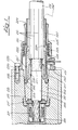
- Medium voltage namely a set in the form of a cable connector for / 10 to 20 kV has an insulating body 202 made of silicone rubber, which is provided with a central longitudinal channel 204 which extends over its entire length.
- a field control body 206 is embedded in the insulating body 202, which consists of a silicone rubber core with an electrically conductive layer applied to it.
- the insulating body lies tightly against the exposed plastic insulation 212 of a conventional plastic-insulated energy supply cable 201 of an energy supply network.
- the conductive layer 211 of this cable is only removed from the plastic insulation to such an extent that it is still removed from the field control can be contacted.
- the diameter of the longitudinal channel 204 is increased towards the end pointing away from the cable end, so that the insulating body 202 does not abut the conductive layer and the end of the cable sheathing and the bent back and under contact with the Cable sheath overlaps shield wires 210.
- the end face of the insulating body 202 facing the cable end lies in the assembled state of the cable connector on a pressure ring 219 which is pushed onto the exposed cable core before a radially resilient plug contact body 218 is fixed thereon.
- the insulating body 202 essentially has a conical outer surface in the area in which it lies tightly against the plastic insulation 212, in order to achieve an electrically tight contact with the correspondingly conical wall of the receiving channel of a socket body 215.
- the socket body 215 consisting of an insulating material forms part of a socket.
- a plug socket 217 is arranged in the socket body 215 following the conical receiving channel, which contacts the plug contact body 218 in the inserted state and which can be connected to a conductor, not shown.
- a shielding bell 217 ′ molded onto the plug socket engages over the pressure ring 219.
- a cylindrical shoulder 205 is formed by a smaller cylindrical section, which extends to the end of the insulating body facing away from the pressure ring 219.
- An annular groove 203 which concentrically surrounds the longitudinal channel 204 and is open towards the annular shoulder 205, is lined with an electrically conductive material to form an annular electrode 208.
- the annular groove 203 has a larger diameter than the end of the field control body 206 with the largest diameter and is so offset from this end of the field control body 206 against the end face resting on the pressure ring such that the ring electrode 208 lies approximately in the region of the field funnel that the field control body defines.
- the cylindrical section of the insulating body 202 is overlapped by a sleeve-shaped pressure body 221 made of electrically insulating material, which is slit several times in the longitudinal direction over part of its length up to the end facing the annular shoulder 205.
- the pressure body 221 forms radially resilient tongues 221 ', the free end of which is designed as a thickened head, the contour of which is adapted to the cross-sectional profile of the ring groove for engagement in the ring groove 203 and for good engagement with the ring electrode 208.
- the tongues 221 'in the radial direction and the relatively small wall thickness of the part of the tongues supporting the head the tongues can easily adapt to the diameter of the annular groove 203, thereby ensuring a good and uniform contact with the annular electrode and the annular groove . This is important both with regard to the contacting of the ring electrode and also with regard to the transmission of the axial force required for an electrically sealed contact of the insulating body 202 with the plastic insulation 212 and with the socket body 215.
- This axial force is generated by means of a prestressed helical compression spring 222 which surrounds the pressure body 221 and is supported on the one hand on a radially outwardly projecting annular shoulder 224 of the pressure body 221 and on the other hand on a shoulder 223 'of a metallic cap 223 which forms the housing of the cable connector. As shown in FIG.
- a sleeve-like extension 227 of the pressure body 221 extends through this smaller, internally cylindrical section of the metallic cap 223, which is formed in one piece with the latter, but has a smaller outer diameter than this.
- a shoulder 228 which faces the shoulder 223 'and therefore limits the displaceability of the pressure body 221 relative to the metallic cap 223 against the force of the helical compression spring 222 for strain relief.
- the displaceability of the pressure body 221 relative to the metallic cap 223 is likewise positively limited, specifically by a circumferential nose 229 on the end portion of the extension 227 which projects beyond the end of the metallic cap 223 facing away from the connecting flange 226.
- the nose 229 engages over this End of the metallic cap 223.
- the elastic deformability of the extension 227 is selected so that the extension can be pushed through the cap 223 from the side of the connecting flange until the nose 229 engages behind the cap end. It would of course also be possible to achieve greater radial suspension of the nose by means of longitudinal slots in the extension.
- the distance of the nose 229 from the shoulder 228 is selected such that the connecting flange 226 is only a relatively small distance from its contact surface 230, which in the exemplary embodiment is the end face of the socket body 215 when the conical section of the insulating body 20th -2- is inserted into the conical outer surface of the receiving channel until it is in contact with all sides.
- the force of the prestressed helical compression spring 222 only needs to be overcome when the connecting screws 225 are now tightened.
- the connecting flange 226 approaches the contact surface 230 until it contacts the same, the force with which the helical spring presses the heads of the tongues 221 ′ into the annular groove 203 increases to the desired value. This ensures an electrically sealed contact of the insulating body 202 both with the plastic insulation 212 and with the socket body 215.
- the head of at least one of the tongues 221 ′ is provided with a contact element (not shown), from which a connecting line 231 is guided along the tongue 221 ′ into the metallic cap 223.
- the connecting line 231 is led out of it through the metallic cap 223.
- the connecting line 231 can be connected to a measuring or testing device.
- the ring electrode is not required for measuring or testing purposes, it can also be connected to earth potential and the ring electrode can thereby be used to improve the field control.
- a connecting line 231 ′ led out through the annular space between the cable 201 and the pressure body 221 and its extension 227 can also be provided.
- the shield wires 210 are insulated from the metallic cap 223 by the extension 227 of the pressure body 221, they can be used to carry out shield or cable jacket measurements if they are not grounded.
- the helical compression spring 222 can only relax until the nose 229 is in contact with the end face of the cap 223 facing it.
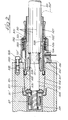
- FIG. 2 The exemplary embodiment shown in FIG. 2 largely corresponds to the exemplary embodiment described above and shown in FIG. 1. Corresponding parts are therefore labeled with a hundred larger reference numbers.
Landscapes
- Cable Accessories (AREA)
- Connector Housings Or Holding Contact Members (AREA)
- Processing Of Terminals (AREA)
Priority Applications (1)
| Application Number | Priority Date | Filing Date | Title |
|---|---|---|---|
| AT81109355T ATE10888T1 (de) | 1981-03-19 | 1981-10-30 | Garnitur fuer das ende eines mittelspannungsoder hochspannungskabels. |
Applications Claiming Priority (2)
| Application Number | Priority Date | Filing Date | Title |
|---|---|---|---|
| DE3110660A DE3110660C2 (de) | 1981-03-19 | 1981-03-19 | Garnitur für das Ende eines Mittelspannnungs- oder Hochspannunskabels |
| DE3110660 | 1981-03-19 |
Publications (2)
| Publication Number | Publication Date |
|---|---|
| EP0060930A1 true EP0060930A1 (fr) | 1982-09-29 |
| EP0060930B1 EP0060930B1 (fr) | 1984-12-19 |
Family
ID=6127687
Family Applications (1)
| Application Number | Title | Priority Date | Filing Date |
|---|---|---|---|
| EP81109355A Expired EP0060930B1 (fr) | 1981-03-19 | 1981-10-30 | Garniture pour l'extrémité d'un câble de moyenne tension ou de haute tension |
Country Status (4)
| Country | Link |
|---|---|
| EP (1) | EP0060930B1 (fr) |
| AT (1) | ATE10888T1 (fr) |
| DE (1) | DE3110660C2 (fr) |
| NO (1) | NO158275C (fr) |
Cited By (5)
| Publication number | Priority date | Publication date | Assignee | Title |
|---|---|---|---|---|
| WO1994023481A1 (fr) * | 1993-03-29 | 1994-10-13 | Karl Pfisterer Elektrotechnische Spezialartikel Gmbh & Co. Kg | Armature pour conducteurs de reseau d'alimentation en energie haute tension et son procede de fabrication |
| EP1646268A2 (fr) * | 2004-10-08 | 2006-04-12 | YXLON International X-Ray GmbH | Dispositif de tension d'un câble haute tension |
| EP1903642A1 (fr) * | 2006-09-25 | 2008-03-26 | Siemens Aktiengesellschaft | Agencement de liaison pour câbles haute tension |
| CN1825715B (zh) * | 2005-02-25 | 2010-05-12 | Nkt电缆有限公司 | 用于仪器或电缆在电设备上连接的插接装置 |
| CN112838553A (zh) * | 2021-03-05 | 2021-05-25 | 夏俊杰 | 纤维水泥电缆管辅助铺设设备 |
Families Citing this family (10)
| Publication number | Priority date | Publication date | Assignee | Title |
|---|---|---|---|---|
| DE3247673C2 (de) * | 1982-12-23 | 1986-02-13 | Karl Pfisterer Elektrotechnische Spezialartikel Gmbh & Co Kg, 7000 Stuttgart | Steckerbuchse mit einem Feldsteuerkörper |
| DE4009358C2 (de) * | 1990-03-23 | 1997-05-15 | Sachsenwerk Ag | Steckbuchse |
| DE4135391C1 (en) * | 1991-10-26 | 1992-12-10 | Karl Pfisterer Elektrotechnische Spezialartikel Gmbh & Co Kg, 7000 Stuttgart, De | Cable connector for medium high voltage and high current - has socket with cup-shaped contact element, and cylindrical insulating housing covering inserted cable |
| DE4212756C2 (de) * | 1992-04-16 | 1994-05-05 | Pfisterer Elektrotech Karl | Stopfen zum elektrisch dichten Verschließen einer Steckbuchse |
| DE4425421C1 (de) * | 1994-07-19 | 1996-02-01 | Pfisterer Elektrotech Karl | Isolierkörper für Kabelendgarnituren, insbesondere Kabelstecker |
| DE19508973C2 (de) * | 1995-03-13 | 2002-04-04 | Abb Patent Gmbh | Kabelgarnitur mit einem ein Kabel hülsenartig umschließenden Druckschieber |
| DE19528126A1 (de) * | 1995-08-01 | 1997-02-06 | Abb Patent Gmbh | Steckvorrichtung für Kabelverbindungen im Hochspannungs-Starkstrombereich |
| DE19806387A1 (de) * | 1998-02-17 | 1999-08-19 | Abb Patent Gmbh | Steckgarnitur zur Kontaktierung eines Innenkonus-Geräteanschlußteils |
| DE10151884A1 (de) * | 2001-10-20 | 2003-04-30 | Alstom | Kabelanschlussteil für eine Mittelspannungsschaltanlage |
| EP3266085B1 (fr) * | 2015-03-03 | 2020-01-15 | Hansjörg GRAMESPACHER | Élément de commande de champ pour fermetures d'extrémité de câbles de transfert d'énergie |
Citations (3)
| Publication number | Priority date | Publication date | Assignee | Title |
|---|---|---|---|---|
| US3517113A (en) * | 1967-10-05 | 1970-06-23 | Hitachi Cable | Cable insertion unit for use in electric cable joint and terminal |
| FR2052753A5 (fr) * | 1969-08-28 | 1971-04-09 | Joslyn Mfg & Supply Co | |
| EP0017953A1 (fr) * | 1979-04-14 | 1980-10-29 | Karl Pfisterer Elektrotechnische Spezialartikel GmbH & Co. KG | Garniture pour l'extrémité d'un câble moyenne tension ou haute tension |
Family Cites Families (1)
| Publication number | Priority date | Publication date | Assignee | Title |
|---|---|---|---|---|
| DE2943080C2 (de) * | 1979-10-25 | 1982-04-08 | Karl Pfisterer Elektrotechnische Spezialartikel Gmbh & Co Kg, 7000 Stuttgart | Garnitur für das Ende eines Mittelspannungs- oder Hochspannungskabels |
-
1981
- 1981-03-19 DE DE3110660A patent/DE3110660C2/de not_active Expired
- 1981-10-30 EP EP81109355A patent/EP0060930B1/fr not_active Expired
- 1981-10-30 AT AT81109355T patent/ATE10888T1/de active
-
1982
- 1982-03-18 NO NO820901A patent/NO158275C/no not_active IP Right Cessation
Patent Citations (3)
| Publication number | Priority date | Publication date | Assignee | Title |
|---|---|---|---|---|
| US3517113A (en) * | 1967-10-05 | 1970-06-23 | Hitachi Cable | Cable insertion unit for use in electric cable joint and terminal |
| FR2052753A5 (fr) * | 1969-08-28 | 1971-04-09 | Joslyn Mfg & Supply Co | |
| EP0017953A1 (fr) * | 1979-04-14 | 1980-10-29 | Karl Pfisterer Elektrotechnische Spezialartikel GmbH & Co. KG | Garniture pour l'extrémité d'un câble moyenne tension ou haute tension |
Non-Patent Citations (2)
| Title |
|---|
| PATENTS ABSTRACTS OF JAPAN, Band 2, Nr. 108, Seite 5781E78, 8. September 1978, & JP-A-53 073 387 (HITACHI) (29-06-1978) * |
| PATENTS ABSTRACTS OF JAPAN, Band 2, Nr. 108, Seite 5782E78, 8. September 1978, & JP-A-53 073 388 (HITACHI) (29-06-1978) * |
Cited By (8)
| Publication number | Priority date | Publication date | Assignee | Title |
|---|---|---|---|---|
| WO1994023481A1 (fr) * | 1993-03-29 | 1994-10-13 | Karl Pfisterer Elektrotechnische Spezialartikel Gmbh & Co. Kg | Armature pour conducteurs de reseau d'alimentation en energie haute tension et son procede de fabrication |
| EP1646268A2 (fr) * | 2004-10-08 | 2006-04-12 | YXLON International X-Ray GmbH | Dispositif de tension d'un câble haute tension |
| EP1646268A3 (fr) * | 2004-10-08 | 2006-07-19 | YXLON International X-Ray GmbH | Dispositif de tension d'un câble haute tension |
| US7517242B2 (en) | 2004-10-08 | 2009-04-14 | Yxlon International X-Ray Gmbh | Clamping device for power cables |
| CN1825715B (zh) * | 2005-02-25 | 2010-05-12 | Nkt电缆有限公司 | 用于仪器或电缆在电设备上连接的插接装置 |
| EP1903642A1 (fr) * | 2006-09-25 | 2008-03-26 | Siemens Aktiengesellschaft | Agencement de liaison pour câbles haute tension |
| CN112838553A (zh) * | 2021-03-05 | 2021-05-25 | 夏俊杰 | 纤维水泥电缆管辅助铺设设备 |
| CN112838553B (zh) * | 2021-03-05 | 2021-12-07 | 苏州爱本科技有限公司 | 纤维水泥电缆管辅助铺设设备 |
Also Published As
| Publication number | Publication date |
|---|---|
| NO158275B (no) | 1988-05-02 |
| ATE10888T1 (de) | 1985-01-15 |
| DE3110660A1 (de) | 1982-11-25 |
| NO820901L (no) | 1982-09-20 |
| EP0060930B1 (fr) | 1984-12-19 |
| DE3110660C2 (de) | 1983-07-14 |
| NO158275C (no) | 1988-08-10 |
Similar Documents
| Publication | Publication Date | Title |
|---|---|---|
| DE1465493C3 (de) | Kabelendteil zum Abschluß oder zur Verbindung abgeschirmter Hochspannungskabel | |
| DE2749028C2 (de) | Hochspannungssteckverbindung | |
| DE69303834T2 (de) | Verbinder zum Anschluss von elektrischen Kabelanordnungen mit verschiedenen Ausführungen | |
| DE2348895C2 (de) | Verbindung für Starkstromkabel | |
| DE2951528C2 (fr) | ||
| DE3110660C2 (de) | Garnitur für das Ende eines Mittelspannnungs- oder Hochspannunskabels | |
| DE102021109667A1 (de) | Steckverbinder mit Schraubverbindung | |
| DE4239648A1 (de) | Steckverbindungseinrichtung für Kabel | |
| DE19615375A1 (de) | Elektrischer Verbinder und Zündvorrichtung für eine Brennkraftmaschine | |
| WO2019145139A1 (fr) | Traversée à haute tension enfichable et appareil électrique comprenant la traversée à haute tension enfichable | |
| DE60302953T2 (de) | Verbinder für zwei elektrische Energiekabel und Verbindung mit einem solchen Verbinder | |
| DE69109060T2 (de) | Steckverbinder für Leitungskabel. | |
| DE3021845A1 (de) | Kabelstecker | |
| EP0017953B1 (fr) | Garniture pour l'extrémité d'un câble moyenne tension ou haute tension | |
| DE4425421C1 (de) | Isolierkörper für Kabelendgarnituren, insbesondere Kabelstecker | |
| DE3420500C2 (fr) | ||
| DE2312897A1 (de) | Hochspannungs-verbindungsvorrichtung, insbesondere fuer geraetedurchfuehrungen | |
| DE3935360C2 (fr) | ||
| EP0651918B1 (fr) | Corps isolant et etanche deformable elastiquement pour connecteur de cables et analogue | |
| DE2410625A1 (de) | Hochspannungs-verbindungsvorrichtung | |
| DE3611463C2 (fr) | ||
| DE3538193C2 (fr) | ||
| EP0459250B1 (fr) | Garniture d'extrémité de câble | |
| DE3886916T2 (de) | Elektrischer Kabelendverbinder zum elektrischen Verbinden von einadrigen Kabeln mit einem Anschluss einer Installation. | |
| EP0636283B1 (fr) | Bouchon pour fermer une prise femelle de maniere garantissant l'isolation electrique |
Legal Events
| Date | Code | Title | Description |
|---|---|---|---|
| PUAI | Public reference made under article 153(3) epc to a published international application that has entered the european phase |
Free format text: ORIGINAL CODE: 0009012 |
|
| AK | Designated contracting states |
Designated state(s): AT BE CH FR GB IT LU NL SE |
|
| 17P | Request for examination filed |
Effective date: 19820924 |
|
| ITF | It: translation for a ep patent filed | ||
| GRAA | (expected) grant |
Free format text: ORIGINAL CODE: 0009210 |
|
| AK | Designated contracting states |
Designated state(s): AT BE CH FR GB IT LI LU NL SE |
|
| REF | Corresponds to: |
Ref document number: 10888 Country of ref document: AT Date of ref document: 19850115 Kind code of ref document: T |
|
| ET | Fr: translation filed | ||
| PLBE | No opposition filed within time limit |
Free format text: ORIGINAL CODE: 0009261 |
|
| STAA | Information on the status of an ep patent application or granted ep patent |
Free format text: STATUS: NO OPPOSITION FILED WITHIN TIME LIMIT |
|
| PG25 | Lapsed in a contracting state [announced via postgrant information from national office to epo] |
Ref country code: LU Free format text: LAPSE BECAUSE OF NON-PAYMENT OF DUE FEES Effective date: 19851031 |
|
| 26N | No opposition filed | ||
| ITTA | It: last paid annual fee | ||
| EAL | Se: european patent in force in sweden |
Ref document number: 81109355.8 |
|
| PGFP | Annual fee paid to national office [announced via postgrant information from national office to epo] |
Ref country code: GB Payment date: 19981013 Year of fee payment: 18 |
|
| PGFP | Annual fee paid to national office [announced via postgrant information from national office to epo] |
Ref country code: BE Payment date: 19981016 Year of fee payment: 18 |
|
| PGFP | Annual fee paid to national office [announced via postgrant information from national office to epo] |
Ref country code: FR Payment date: 19981027 Year of fee payment: 18 |
|
| PGFP | Annual fee paid to national office [announced via postgrant information from national office to epo] |
Ref country code: NL Payment date: 19981030 Year of fee payment: 18 |
|
| PGFP | Annual fee paid to national office [announced via postgrant information from national office to epo] |
Ref country code: AT Payment date: 19981031 Year of fee payment: 18 |
|
| REG | Reference to a national code |
Ref country code: CH Ref legal event code: PFA Free format text: KARL PFISTERER ELEKTROTECHNISCHE SPEZIALARTIKEL GMBH & CO. KG TRANSFER- PFISTERER KONTAKTSYSTEME GMBH & CO. KG |
|
| PG25 | Lapsed in a contracting state [announced via postgrant information from national office to epo] |
Ref country code: GB Free format text: LAPSE BECAUSE OF NON-PAYMENT OF DUE FEES Effective date: 19991030 Ref country code: AT Free format text: LAPSE BECAUSE OF NON-PAYMENT OF DUE FEES Effective date: 19991030 |
|
| PG25 | Lapsed in a contracting state [announced via postgrant information from national office to epo] |
Ref country code: BE Free format text: LAPSE BECAUSE OF NON-PAYMENT OF DUE FEES Effective date: 19991031 |
|
| BERE | Be: lapsed |
Owner name: KARL PFISTERER ELEKTROTECHNISCHE SPEZIALARTIKEL G Effective date: 19991031 |
|
| PG25 | Lapsed in a contracting state [announced via postgrant information from national office to epo] |
Ref country code: NL Free format text: LAPSE BECAUSE OF NON-PAYMENT OF DUE FEES Effective date: 20000501 |
|
| GBPC | Gb: european patent ceased through non-payment of renewal fee |
Effective date: 19991030 |
|
| PG25 | Lapsed in a contracting state [announced via postgrant information from national office to epo] |
Ref country code: FR Free format text: LAPSE BECAUSE OF NON-PAYMENT OF DUE FEES Effective date: 20000630 |
|
| NLV4 | Nl: lapsed or anulled due to non-payment of the annual fee |
Effective date: 20000501 |
|
| REG | Reference to a national code |
Ref country code: FR Ref legal event code: ST |
|
| PGFP | Annual fee paid to national office [announced via postgrant information from national office to epo] |
Ref country code: SE Payment date: 20010131 Year of fee payment: 20 Ref country code: CH Payment date: 20010131 Year of fee payment: 20 |
|
| PG25 | Lapsed in a contracting state [announced via postgrant information from national office to epo] |
Ref country code: LI Free format text: LAPSE BECAUSE OF EXPIRATION OF PROTECTION Effective date: 20011029 Ref country code: CH Free format text: LAPSE BECAUSE OF EXPIRATION OF PROTECTION Effective date: 20011029 |
|
| PG25 | Lapsed in a contracting state [announced via postgrant information from national office to epo] |
Ref country code: SE Free format text: THE PATENT HAS BEEN ANNULLED BY A DECISION OF A NATIONAL AUTHORITY Effective date: 20011030 |
|
| REG | Reference to a national code |
Ref country code: CH Ref legal event code: PL |
|
| EUG | Se: european patent has lapsed |
Ref document number: 81109355.8 |