EP0060720A1 - Convoyeurs - Google Patents
Convoyeurs Download PDFInfo
- Publication number
- EP0060720A1 EP0060720A1 EP82301338A EP82301338A EP0060720A1 EP 0060720 A1 EP0060720 A1 EP 0060720A1 EP 82301338 A EP82301338 A EP 82301338A EP 82301338 A EP82301338 A EP 82301338A EP 0060720 A1 EP0060720 A1 EP 0060720A1
- Authority
- EP
- European Patent Office
- Prior art keywords
- support members
- pair
- members
- conveyor system
- object support
- Prior art date
- Legal status (The legal status is an assumption and is not a legal conclusion. Google has not performed a legal analysis and makes no representation as to the accuracy of the status listed.)
- Ceased
Links
Images
Classifications
-
- B—PERFORMING OPERATIONS; TRANSPORTING
- B65—CONVEYING; PACKING; STORING; HANDLING THIN OR FILAMENTARY MATERIAL
- B65G—TRANSPORT OR STORAGE DEVICES, e.g. CONVEYORS FOR LOADING OR TIPPING, SHOP CONVEYOR SYSTEMS OR PNEUMATIC TUBE CONVEYORS
- B65G37/00—Combinations of mechanical conveyors of the same kind, or of different kinds, of interest apart from their application in particular machines or use in particular manufacturing processes
- B65G37/005—Combinations of mechanical conveyors of the same kind, or of different kinds, of interest apart from their application in particular machines or use in particular manufacturing processes comprising two or more co-operating conveying elements with parallel longitudinal axes
-
- B—PERFORMING OPERATIONS; TRANSPORTING
- B65—CONVEYING; PACKING; STORING; HANDLING THIN OR FILAMENTARY MATERIAL
- B65B—MACHINES, APPARATUS OR DEVICES FOR, OR METHODS OF, PACKAGING ARTICLES OR MATERIALS; UNPACKING
- B65B43/00—Forming, feeding, opening or setting-up containers or receptacles in association with packaging
- B65B43/42—Feeding or positioning bags, boxes, or cartons in the distended, opened, or set-up state; Feeding preformed rigid containers, e.g. tins, capsules, glass tubes, glasses, to the packaging position; Locating containers or receptacles at the filling position; Supporting containers or receptacles during the filling operation
- B65B43/54—Means for supporting containers or receptacles during the filling operation
-
- B—PERFORMING OPERATIONS; TRANSPORTING
- B65—CONVEYING; PACKING; STORING; HANDLING THIN OR FILAMENTARY MATERIAL
- B65B—MACHINES, APPARATUS OR DEVICES FOR, OR METHODS OF, PACKAGING ARTICLES OR MATERIALS; UNPACKING
- B65B59/00—Arrangements to enable machines to handle articles of different sizes, to produce packages of different sizes, to vary the contents of packages, to handle different types of packaging material, or to give access for cleaning or maintenance purposes
- B65B59/003—Arrangements to enable adjustments related to the packaging material
-
- B—PERFORMING OPERATIONS; TRANSPORTING
- B65—CONVEYING; PACKING; STORING; HANDLING THIN OR FILAMENTARY MATERIAL
- B65B—MACHINES, APPARATUS OR DEVICES FOR, OR METHODS OF, PACKAGING ARTICLES OR MATERIALS; UNPACKING
- B65B59/00—Arrangements to enable machines to handle articles of different sizes, to produce packages of different sizes, to vary the contents of packages, to handle different types of packaging material, or to give access for cleaning or maintenance purposes
- B65B59/005—Adjustable conveying means
-
- B—PERFORMING OPERATIONS; TRANSPORTING
- B65—CONVEYING; PACKING; STORING; HANDLING THIN OR FILAMENTARY MATERIAL
- B65G—TRANSPORT OR STORAGE DEVICES, e.g. CONVEYORS FOR LOADING OR TIPPING, SHOP CONVEYOR SYSTEMS OR PNEUMATIC TUBE CONVEYORS
- B65G17/00—Conveyors having an endless traction element, e.g. a chain, transmitting movement to a continuous or substantially-continuous load-carrying surface or to a series of individual load-carriers; Endless-chain conveyors in which the chains form the load-carrying surface
- B65G17/26—Conveyors having an endless traction element, e.g. a chain, transmitting movement to a continuous or substantially-continuous load-carrying surface or to a series of individual load-carriers; Endless-chain conveyors in which the chains form the load-carrying surface comprising a series of co-operating units, e.g. interconnected by pivots
-
- B—PERFORMING OPERATIONS; TRANSPORTING
- B65—CONVEYING; PACKING; STORING; HANDLING THIN OR FILAMENTARY MATERIAL
- B65G—TRANSPORT OR STORAGE DEVICES, e.g. CONVEYORS FOR LOADING OR TIPPING, SHOP CONVEYOR SYSTEMS OR PNEUMATIC TUBE CONVEYORS
- B65G2201/00—Indexing codes relating to handling devices, e.g. conveyors, characterised by the type of product or load being conveyed or handled
- B65G2201/02—Articles
Definitions
- This invention relates to a conveyor which may be adjusted to convey objects of different sizes, such as containers.
- a conveyor system is required to handle different sized objects at different times and where the objects cannot be randomly placed on the conveyor.
- One prime example of such a conveyor is that used to feed containers through washing equipment and/or to filling or capping equipment. It is common for such equipment to be used to wash, fill, or cap different size containers when different commodities are being placed in the containers and also to have different size containers for receiving different quantities of the same commodity.
- a conveyor adjustable to transport objects of different sizes comprising two endless flexible members supported so at least one flight of each flexible member move on parallel laterally spaced paths, a plurality of pairs of object support members, each said support member of each said pair being connected to one of the endless flexible members so as to define respective object receiving spaces therebetween, and means to selectively adjust the relative longitudinal spacing between the object support members of each said pair to accommodate different sized objects in said object receiving areas.
- the support members of each said pair are respectively connected to a different one of said endless flexible members and the means to adjust the relative longitudinal spacing of the object support members comprises means to vary the phasing of the respective flights of the flexible members along said parallel spaced paths.
- This arrangement enables the space between the support members of each pair to be varied in the direction of movement along the paths without the inconvenience of varying the position of every one of the support members.
- Each endless flexible member is supported on one idler and one drive pulley or "sprocket so that one flight of each flexible member moves along the said parallel laterally spaced paths.
- the two drive pulleys or sprockets are coupled to a common drive shaft so as to rotate in unison and the mounting of one of the drive pulleys or sprockets on the shaft is such that it may be angularly spaced about the axis of the drive shaft relative to the other drive pulley or sprocket.
- the phasing of the movement of the two flexible members along the respective paths can be adjusted and hence the spacing between the respective support members of each pair can be varied to receive different sized objects.
- the object support members of each pair carry co-operating guide elements so that during the adjustment of the spacing therebetween the members undergo a substantially pure linear movement relative to one another.
- the guide elements may be in the form of a pin carried by one of the members slidably received in an aperture in the other member.
- Stationary guide rails may be provided adjacent each of the two opposite sides of the path of the endless flexible members to prevent displacement in the lateral direction of objects located on the conveyor.
- the spacing of these stationary guide members relative to the flexible endless members may be adjustable to accommodate objects of different lateral dimensions. This adjustment is independent of the adjustment of the spacing between the respective members of each pair of object support members.
- the conveyor may be used so that the objects are carried thereby along two flights, one spaced vertically from the other so that the objects are inverted as they move from one flight to the other.
- a further guide bar spaced below the flexible members so as to engage the lower part of the objects and retain them in co-operation with the conveyor and respective object support members as they travel along the lower flight of the conveyor.
- this guide member will also extend around substantially the lower half of the curved part of the conveyor travel as it moves between the upper and lower flights so as to again retain the objects in position on the conveyor as they are moved into and out of the inverted position.
- the conveyor system in general comprises a base frame having journalled thereon a pair of co-axial idler sprockets and a pair of co-axial drive sprockets.
- the respective pairs being mounted with their axes horizontally spaced and parallel.
- the two idler sprockets are free to rotate independently to one another on their common axis and the two driven sprockets are coupled together to be driven in unison through a common drive mechanism from an electric motor.
- Two endless chains are mounted on respective drive and idler sprockets so as to operate in laterally spaced vertical planes with upper and lower parallel horizontal flights.
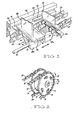
- Figure 2 shows a pair of drive sprockets 10,11 coupled to a common drive shaft 13 through a flanged boss 12 keyed to the drive shaft 13.
- One sprocket 10 is secured in a fixed relation to the flange of the boss 12 and the other sprocket 11 is adjustably mounted to the flange so that it may be rotated about the axis of the shaft 13 relative to the flange and hence relative to the other sprocket 10.
- This adjustment is controlled by a plurality of bolts 14 extending through arcuate slots 15. in the adjustable sprocket 11 and threadably engaged in holes in the flange of the boss 12.
- FIG. 1 illustrates one pair of object support members 24,25 supported on the chains 20,21. It will be appreciated that a plurality of such pairs of object support members would normally be included in the conveyor system.
- Each member 24,25, of each pair comprises a base section 26,27, extending transversely of the two chains and an upright section 28,29, extending from the base section outwardly from the chains.
- the two base sections 26,27, of the pair of members forms a base support upon which the object to be carried may rest, and the upright sections 28,29, engage the opposite sides of the object to retain it in position on the base sections as it is carried along by the chains 20,21.
- each base section 26,27, of each pair of members'24,25 there is provided a bracket 26a, 27a, which extend down between the two chains 20,21 with bracket 26a coupled by pin 30 to the chain 20, and the bracket 27a coupled by pin 31 to the other chain 21.
- the pins 30,31 each comprise an elongated shank which passes through bores in the respective chains pivot connections as well as a bore in the respective brackets 26a,27a.
- the pins 30,31 are maintained in position by split pins 40 or other similar fastener means and enlarged cylindrical head portions 41,42 respectively.
- the two support members 24,25, of each pair will travel along the path of the chains in unison, however the spacing between the members 24,25, can be adjusted by adjustment of the angular relationship of the two drive sprockets 11,10, as previously described as the members 24,25 are secured only to a respective one of the chains 20,21.
- bracket 27a of each pair of members 24,25 has a pin 32 attached thereto extending generally parallel to the chains 20,21, the pin 32 being slidably received in an aperture 33 in the bracket 26a of the other member of the pair.
- the apertured bracket 26a can slide along the pin 32.
- the two brackets are held in a fixed relationship by the pin 32, so that the upright sections.28,29, of each of the members remain in a fixed relationship, normally being parallel.
- a guide rail 43 is provided extending generally parallel to and laterally spaced from the chains 20,21.
- a second similar guide rail may conveniently be provided on the opposite side of the chains 20,21.
- the guide rail 43 has a longitudinally extending groove 44 arranged to engage the enlarged cylindrical head 41 of the pin 30.
- the conveyor system preferably includes means (not shown) for adjusting the position of further guide or support rails relative to the chains 20,21. This adjustment provides allowance for containers having varying lateral width sizes.
- At least one adjustable support guide rail is provided beneath the lower flight of the conveyor chains 20,21 to maintain objects carried by the conveyor in engagement with the object support members.
- the containers move along the lower flight of the conveyor they pass through the path of a number of jets which may issue either air or liquid into the open end of the container to wash the interior thereof. It will however be appreciated that this same conveyor may be used in a number of other applications where it is required to convey at different times, different sized objects.
Applications Claiming Priority (2)
| Application Number | Priority Date | Filing Date | Title |
|---|---|---|---|
| AU802781 | 1981-03-17 | ||
| AU8027/81 | 1981-03-17 |
Publications (1)
| Publication Number | Publication Date |
|---|---|
| EP0060720A1 true EP0060720A1 (fr) | 1982-09-22 |
Family
ID=3698683
Family Applications (1)
| Application Number | Title | Priority Date | Filing Date |
|---|---|---|---|
| EP82301338A Ceased EP0060720A1 (fr) | 1981-03-17 | 1982-03-16 | Convoyeurs |
Country Status (2)
| Country | Link |
|---|---|
| EP (1) | EP0060720A1 (fr) |
| AU (1) | AU8158682A (fr) |
Cited By (12)
| Publication number | Priority date | Publication date | Assignee | Title |
|---|---|---|---|---|
| EP0486868A1 (fr) * | 1990-11-17 | 1992-05-27 | FRIEDRICH THEYSOHN GmbH | Dispositif pour tirer des profilés allongés |
| FR2669890A1 (fr) * | 1991-11-29 | 1992-06-05 | Baumer Srl | Appareil permettant de regrouper des articles, devant etre fournis, d'une maniere continue, a une machine d'emballage. |
| ES2051181A2 (es) * | 1990-12-03 | 1994-06-01 | Baumer Srl | Medios para agrupar articulos lado a lado, transversalmente o longitudinalmente, en grupos de cantidades variables para la alimentacion continua a maquinas de embalaje. |
| EP0621468A1 (fr) * | 1993-04-23 | 1994-10-26 | Hi-Speed Checkweigher Co., Inc. | Plateau de pesée variable |
| EP0709313A1 (fr) * | 1994-10-20 | 1996-05-01 | Riverwood International Corporation | Dispositif convoyeur pour espacer |
| EP0831028A1 (fr) * | 1996-09-20 | 1998-03-25 | Benz & Hilgers GmbH | Convoyeur pour une machine de remplissage et/ou de bouchage |
| EP0893374A1 (fr) | 1997-06-13 | 1999-01-27 | Aries Packaging S.A. | Mecanisme d'espacement et transfert de produits en continu à trois chaines |
| EP0930249A1 (fr) * | 1998-01-15 | 1999-07-21 | IWK Verpackungstechnik GmbH | Transporteur dans une machine d'emballage |
| EP0945372A2 (fr) * | 1998-03-25 | 1999-09-29 | Rovema Verpackungsmaschinen GmbH | Dispositif et procédé pour transporter des articles |
| NL1013509C2 (nl) * | 1999-11-05 | 2001-05-08 | Bouwe Prakken | Transportbaan van het type smart track. |
| DE102008039036A1 (de) * | 2008-08-21 | 2010-06-10 | Harting Applied Technologies Gmbh & Co. Kg | Lineartransportvorrichtung |
| CN111994542A (zh) * | 2019-09-05 | 2020-11-27 | 苏春英 | 一种物流运输控制方法 |
Families Citing this family (1)
| Publication number | Priority date | Publication date | Assignee | Title |
|---|---|---|---|---|
| US4642975A (en) * | 1986-02-03 | 1987-02-17 | H. J. Langen & Sons Limited | Carton loading machine |
Citations (1)
| Publication number | Priority date | Publication date | Assignee | Title |
|---|---|---|---|---|
| DE1511643B2 (de) * | 1966-10-13 | 1975-07-31 | Fr. Hesser Maschinenfabrik Ag, 7000 Stuttgart | Fördereinrichtung an einer Verpackungsmaschine mit einer schrittweise bewegten Förderkette |
-
1981
- 1981-03-17 AU AU81586/82A patent/AU8158682A/en not_active Abandoned
-
1982
- 1982-03-16 EP EP82301338A patent/EP0060720A1/fr not_active Ceased
Patent Citations (1)
| Publication number | Priority date | Publication date | Assignee | Title |
|---|---|---|---|---|
| DE1511643B2 (de) * | 1966-10-13 | 1975-07-31 | Fr. Hesser Maschinenfabrik Ag, 7000 Stuttgart | Fördereinrichtung an einer Verpackungsmaschine mit einer schrittweise bewegten Förderkette |
Cited By (18)
| Publication number | Priority date | Publication date | Assignee | Title |
|---|---|---|---|---|
| EP0486868A1 (fr) * | 1990-11-17 | 1992-05-27 | FRIEDRICH THEYSOHN GmbH | Dispositif pour tirer des profilés allongés |
| ES2051181A2 (es) * | 1990-12-03 | 1994-06-01 | Baumer Srl | Medios para agrupar articulos lado a lado, transversalmente o longitudinalmente, en grupos de cantidades variables para la alimentacion continua a maquinas de embalaje. |
| FR2669890A1 (fr) * | 1991-11-29 | 1992-06-05 | Baumer Srl | Appareil permettant de regrouper des articles, devant etre fournis, d'une maniere continue, a une machine d'emballage. |
| EP0621468A1 (fr) * | 1993-04-23 | 1994-10-26 | Hi-Speed Checkweigher Co., Inc. | Plateau de pesée variable |
| EP0709313A1 (fr) * | 1994-10-20 | 1996-05-01 | Riverwood International Corporation | Dispositif convoyeur pour espacer |
| US5657615A (en) * | 1994-10-20 | 1997-08-19 | Riverwood International Corporation | Spacing conveyor mechanism |
| US5915524A (en) * | 1996-09-20 | 1999-06-29 | Benhil Gasti Verpackungsmaschinen Gmbh | Conveyor for a container filling/capping machine |
| EP0831028A1 (fr) * | 1996-09-20 | 1998-03-25 | Benz & Hilgers GmbH | Convoyeur pour une machine de remplissage et/ou de bouchage |
| EP0893374A1 (fr) | 1997-06-13 | 1999-01-27 | Aries Packaging S.A. | Mecanisme d'espacement et transfert de produits en continu à trois chaines |
| EP0930249A1 (fr) * | 1998-01-15 | 1999-07-21 | IWK Verpackungstechnik GmbH | Transporteur dans une machine d'emballage |
| EP0945372A2 (fr) * | 1998-03-25 | 1999-09-29 | Rovema Verpackungsmaschinen GmbH | Dispositif et procédé pour transporter des articles |
| EP0945372A3 (fr) * | 1998-03-25 | 2000-09-06 | Rovema Verpackungsmaschinen GmbH | Dispositif et procédé pour transporter des articles |
| NL1013509C2 (nl) * | 1999-11-05 | 2001-05-08 | Bouwe Prakken | Transportbaan van het type smart track. |
| WO2001032535A1 (fr) * | 1999-11-05 | 2001-05-10 | Bouwe Prakken | Chenille a convoyeurs du type intelligent |
| US6691856B1 (en) | 1999-11-05 | 2004-02-17 | Bouwe Prakken | Conveyor track of the smart-track type |
| DE102008039036A1 (de) * | 2008-08-21 | 2010-06-10 | Harting Applied Technologies Gmbh & Co. Kg | Lineartransportvorrichtung |
| DE102008039036B4 (de) * | 2008-08-21 | 2011-07-14 | HARTING Applied Technologies GmbH & Co. KG, 32339 | Lineartransportvorrichtung |
| CN111994542A (zh) * | 2019-09-05 | 2020-11-27 | 苏春英 | 一种物流运输控制方法 |
Also Published As
| Publication number | Publication date |
|---|---|
| AU8158682A (en) | 1982-09-23 |
Similar Documents
| Publication | Publication Date | Title |
|---|---|---|
| EP0060720A1 (fr) | Convoyeurs | |
| US4676361A (en) | Troughing conveyors for carton or bag orienting and conveying | |
| US6634487B2 (en) | Conveying apparatus for forming and loading groups of containers | |
| US5638659A (en) | Packaging machine | |
| KR100454350B1 (ko) | 멀티팩포장장치 | |
| US5291988A (en) | Adjustable guide rail apparatus for conveyor systems | |
| EP0708028B1 (fr) | Mécanisme convoyeur pour espacer des articles | |
| EP0806384A2 (fr) | Système de transport | |
| US5161665A (en) | Lane merger apparatus | |
| US4936072A (en) | Container filler and sealer with two directional flexing chain | |
| US4534153A (en) | Method and apparatus for packing plastic bottles | |
| US20040094388A1 (en) | Conveyor and method for conveying products | |
| US4850472A (en) | Conveyor apparatus | |
| JPH06313727A (ja) | 検査秤量装置及び秤量方法 | |
| GB2270059A (en) | A station for distributing products. | |
| JPH06191617A (ja) | 容器搬送装置 | |
| US6691856B1 (en) | Conveyor track of the smart-track type | |
| KR20080033136A (ko) | 세장형 식품을 이송하기 위한 장치 및 방법 | |
| US8678174B2 (en) | Method and device for buffering products | |
| US5197586A (en) | Automatic machine for uprightly positioning and feeding containers | |
| US4934516A (en) | Apparatus for supporting an article conveying system | |
| US3575278A (en) | Apparatus for selectively receiving and aligning packages | |
| NL8120035A (nl) | Inrichting voor het op zijn kop behandelen van flessen en dergelijke. | |
| US5054257A (en) | Cut-off device for can-container packaging equipment | |
| US3292767A (en) | Processing machine feeding means |
Legal Events
| Date | Code | Title | Description |
|---|---|---|---|
| PUAI | Public reference made under article 153(3) epc to a published international application that has entered the european phase |
Free format text: ORIGINAL CODE: 0009012 |
|
| AK | Designated contracting states |
Designated state(s): CH DE FR GB IT LI NL |
|
| 17P | Request for examination filed |
Effective date: 19830223 |
|
| STAA | Information on the status of an ep patent application or granted ep patent |
Free format text: STATUS: THE APPLICATION HAS BEEN REFUSED |
|
| 18R | Application refused |
Effective date: 19841027 |