EP0060720A1 - Improvements relating to conveyors - Google Patents
Improvements relating to conveyors Download PDFInfo
- Publication number
- EP0060720A1 EP0060720A1 EP82301338A EP82301338A EP0060720A1 EP 0060720 A1 EP0060720 A1 EP 0060720A1 EP 82301338 A EP82301338 A EP 82301338A EP 82301338 A EP82301338 A EP 82301338A EP 0060720 A1 EP0060720 A1 EP 0060720A1
- Authority
- EP
- European Patent Office
- Prior art keywords
- support members
- pair
- members
- conveyor system
- object support
- Prior art date
- Legal status (The legal status is an assumption and is not a legal conclusion. Google has not performed a legal analysis and makes no representation as to the accuracy of the status listed.)
- Ceased
Links
Images
Classifications
-
- B—PERFORMING OPERATIONS; TRANSPORTING
- B65—CONVEYING; PACKING; STORING; HANDLING THIN OR FILAMENTARY MATERIAL
- B65G—TRANSPORT OR STORAGE DEVICES, e.g. CONVEYORS FOR LOADING OR TIPPING, SHOP CONVEYOR SYSTEMS OR PNEUMATIC TUBE CONVEYORS
- B65G37/00—Combinations of mechanical conveyors of the same kind, or of different kinds, of interest apart from their application in particular machines or use in particular manufacturing processes
- B65G37/005—Combinations of mechanical conveyors of the same kind, or of different kinds, of interest apart from their application in particular machines or use in particular manufacturing processes comprising two or more co-operating conveying elements with parallel longitudinal axes
-
- B—PERFORMING OPERATIONS; TRANSPORTING
- B65—CONVEYING; PACKING; STORING; HANDLING THIN OR FILAMENTARY MATERIAL
- B65B—MACHINES, APPARATUS OR DEVICES FOR, OR METHODS OF, PACKAGING ARTICLES OR MATERIALS; UNPACKING
- B65B43/00—Forming, feeding, opening or setting-up containers or receptacles in association with packaging
- B65B43/42—Feeding or positioning bags, boxes, or cartons in the distended, opened, or set-up state; Feeding preformed rigid containers, e.g. tins, capsules, glass tubes, glasses, to the packaging position; Locating containers or receptacles at the filling position; Supporting containers or receptacles during the filling operation
- B65B43/54—Means for supporting containers or receptacles during the filling operation
-
- B—PERFORMING OPERATIONS; TRANSPORTING
- B65—CONVEYING; PACKING; STORING; HANDLING THIN OR FILAMENTARY MATERIAL
- B65B—MACHINES, APPARATUS OR DEVICES FOR, OR METHODS OF, PACKAGING ARTICLES OR MATERIALS; UNPACKING
- B65B59/00—Arrangements to enable machines to handle articles of different sizes, to produce packages of different sizes, to vary the contents of packages, to handle different types of packaging material, or to give access for cleaning or maintenance purposes
- B65B59/003—Arrangements to enable adjustments related to the packaging material
-
- B—PERFORMING OPERATIONS; TRANSPORTING
- B65—CONVEYING; PACKING; STORING; HANDLING THIN OR FILAMENTARY MATERIAL
- B65B—MACHINES, APPARATUS OR DEVICES FOR, OR METHODS OF, PACKAGING ARTICLES OR MATERIALS; UNPACKING
- B65B59/00—Arrangements to enable machines to handle articles of different sizes, to produce packages of different sizes, to vary the contents of packages, to handle different types of packaging material, or to give access for cleaning or maintenance purposes
- B65B59/005—Adjustable conveying means
-
- B—PERFORMING OPERATIONS; TRANSPORTING
- B65—CONVEYING; PACKING; STORING; HANDLING THIN OR FILAMENTARY MATERIAL
- B65G—TRANSPORT OR STORAGE DEVICES, e.g. CONVEYORS FOR LOADING OR TIPPING, SHOP CONVEYOR SYSTEMS OR PNEUMATIC TUBE CONVEYORS
- B65G17/00—Conveyors having an endless traction element, e.g. a chain, transmitting movement to a continuous or substantially-continuous load-carrying surface or to a series of individual load-carriers; Endless-chain conveyors in which the chains form the load-carrying surface
- B65G17/26—Conveyors having an endless traction element, e.g. a chain, transmitting movement to a continuous or substantially-continuous load-carrying surface or to a series of individual load-carriers; Endless-chain conveyors in which the chains form the load-carrying surface comprising a series of co-operating units, e.g. interconnected by pivots
-
- B—PERFORMING OPERATIONS; TRANSPORTING
- B65—CONVEYING; PACKING; STORING; HANDLING THIN OR FILAMENTARY MATERIAL
- B65G—TRANSPORT OR STORAGE DEVICES, e.g. CONVEYORS FOR LOADING OR TIPPING, SHOP CONVEYOR SYSTEMS OR PNEUMATIC TUBE CONVEYORS
- B65G2201/00—Indexing codes relating to handling devices, e.g. conveyors, characterised by the type of product or load being conveyed or handled
- B65G2201/02—Articles
Definitions
- This invention relates to a conveyor which may be adjusted to convey objects of different sizes, such as containers.
- a conveyor system is required to handle different sized objects at different times and where the objects cannot be randomly placed on the conveyor.
- One prime example of such a conveyor is that used to feed containers through washing equipment and/or to filling or capping equipment. It is common for such equipment to be used to wash, fill, or cap different size containers when different commodities are being placed in the containers and also to have different size containers for receiving different quantities of the same commodity.
- a conveyor adjustable to transport objects of different sizes comprising two endless flexible members supported so at least one flight of each flexible member move on parallel laterally spaced paths, a plurality of pairs of object support members, each said support member of each said pair being connected to one of the endless flexible members so as to define respective object receiving spaces therebetween, and means to selectively adjust the relative longitudinal spacing between the object support members of each said pair to accommodate different sized objects in said object receiving areas.
- the support members of each said pair are respectively connected to a different one of said endless flexible members and the means to adjust the relative longitudinal spacing of the object support members comprises means to vary the phasing of the respective flights of the flexible members along said parallel spaced paths.
- This arrangement enables the space between the support members of each pair to be varied in the direction of movement along the paths without the inconvenience of varying the position of every one of the support members.
- Each endless flexible member is supported on one idler and one drive pulley or "sprocket so that one flight of each flexible member moves along the said parallel laterally spaced paths.
- the two drive pulleys or sprockets are coupled to a common drive shaft so as to rotate in unison and the mounting of one of the drive pulleys or sprockets on the shaft is such that it may be angularly spaced about the axis of the drive shaft relative to the other drive pulley or sprocket.
- the phasing of the movement of the two flexible members along the respective paths can be adjusted and hence the spacing between the respective support members of each pair can be varied to receive different sized objects.
- the object support members of each pair carry co-operating guide elements so that during the adjustment of the spacing therebetween the members undergo a substantially pure linear movement relative to one another.
- the guide elements may be in the form of a pin carried by one of the members slidably received in an aperture in the other member.
- Stationary guide rails may be provided adjacent each of the two opposite sides of the path of the endless flexible members to prevent displacement in the lateral direction of objects located on the conveyor.
- the spacing of these stationary guide members relative to the flexible endless members may be adjustable to accommodate objects of different lateral dimensions. This adjustment is independent of the adjustment of the spacing between the respective members of each pair of object support members.
- the conveyor may be used so that the objects are carried thereby along two flights, one spaced vertically from the other so that the objects are inverted as they move from one flight to the other.
- a further guide bar spaced below the flexible members so as to engage the lower part of the objects and retain them in co-operation with the conveyor and respective object support members as they travel along the lower flight of the conveyor.
- this guide member will also extend around substantially the lower half of the curved part of the conveyor travel as it moves between the upper and lower flights so as to again retain the objects in position on the conveyor as they are moved into and out of the inverted position.
- the conveyor system in general comprises a base frame having journalled thereon a pair of co-axial idler sprockets and a pair of co-axial drive sprockets.
- the respective pairs being mounted with their axes horizontally spaced and parallel.
- the two idler sprockets are free to rotate independently to one another on their common axis and the two driven sprockets are coupled together to be driven in unison through a common drive mechanism from an electric motor.
- Two endless chains are mounted on respective drive and idler sprockets so as to operate in laterally spaced vertical planes with upper and lower parallel horizontal flights.
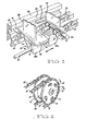
- Figure 2 shows a pair of drive sprockets 10,11 coupled to a common drive shaft 13 through a flanged boss 12 keyed to the drive shaft 13.
- One sprocket 10 is secured in a fixed relation to the flange of the boss 12 and the other sprocket 11 is adjustably mounted to the flange so that it may be rotated about the axis of the shaft 13 relative to the flange and hence relative to the other sprocket 10.
- This adjustment is controlled by a plurality of bolts 14 extending through arcuate slots 15. in the adjustable sprocket 11 and threadably engaged in holes in the flange of the boss 12.
- FIG. 1 illustrates one pair of object support members 24,25 supported on the chains 20,21. It will be appreciated that a plurality of such pairs of object support members would normally be included in the conveyor system.
- Each member 24,25, of each pair comprises a base section 26,27, extending transversely of the two chains and an upright section 28,29, extending from the base section outwardly from the chains.
- the two base sections 26,27, of the pair of members forms a base support upon which the object to be carried may rest, and the upright sections 28,29, engage the opposite sides of the object to retain it in position on the base sections as it is carried along by the chains 20,21.
- each base section 26,27, of each pair of members'24,25 there is provided a bracket 26a, 27a, which extend down between the two chains 20,21 with bracket 26a coupled by pin 30 to the chain 20, and the bracket 27a coupled by pin 31 to the other chain 21.
- the pins 30,31 each comprise an elongated shank which passes through bores in the respective chains pivot connections as well as a bore in the respective brackets 26a,27a.
- the pins 30,31 are maintained in position by split pins 40 or other similar fastener means and enlarged cylindrical head portions 41,42 respectively.
- the two support members 24,25, of each pair will travel along the path of the chains in unison, however the spacing between the members 24,25, can be adjusted by adjustment of the angular relationship of the two drive sprockets 11,10, as previously described as the members 24,25 are secured only to a respective one of the chains 20,21.
- bracket 27a of each pair of members 24,25 has a pin 32 attached thereto extending generally parallel to the chains 20,21, the pin 32 being slidably received in an aperture 33 in the bracket 26a of the other member of the pair.
- the apertured bracket 26a can slide along the pin 32.
- the two brackets are held in a fixed relationship by the pin 32, so that the upright sections.28,29, of each of the members remain in a fixed relationship, normally being parallel.
- a guide rail 43 is provided extending generally parallel to and laterally spaced from the chains 20,21.
- a second similar guide rail may conveniently be provided on the opposite side of the chains 20,21.
- the guide rail 43 has a longitudinally extending groove 44 arranged to engage the enlarged cylindrical head 41 of the pin 30.
- the conveyor system preferably includes means (not shown) for adjusting the position of further guide or support rails relative to the chains 20,21. This adjustment provides allowance for containers having varying lateral width sizes.
- At least one adjustable support guide rail is provided beneath the lower flight of the conveyor chains 20,21 to maintain objects carried by the conveyor in engagement with the object support members.
- the containers move along the lower flight of the conveyor they pass through the path of a number of jets which may issue either air or liquid into the open end of the container to wash the interior thereof. It will however be appreciated that this same conveyor may be used in a number of other applications where it is required to convey at different times, different sized objects.
Abstract
A conveyor system capable of adjustment to allow articles of different sizes to be carried thereby, the conveyor system comprising two endless flexible members (20, 21) carrying a plurality of pairs of article supporting members (24, 25) whereby respective article supporting members of each pair are connected to a different one of the endless flexible members (20, 21), and means for varying the longitudinal spacing between the supporting members (24, 25) including connectors (30, 31) and/or means (10, 11) for varying the phase of the respective endless flexible members (20, 21).
Description
- This invention relates to a conveyor which may be adjusted to convey objects of different sizes, such as containers.
- There are many applications in industry where a conveyor system is required to handle different sized objects at different times and where the objects cannot be randomly placed on the conveyor. One prime example of such a conveyor is that used to feed containers through washing equipment and/or to filling or capping equipment. It is common for such equipment to be used to wash, fill, or cap different size containers when different commodities are being placed in the containers and also to have different size containers for receiving different quantities of the same commodity. In many applications it is necessary for the spacing of the containers on the conveyor to be accurately controlled so that they will register correctly with various stations in the associated equipment, such as for the purposes of filling the container or apply a closure thereto. It is therefore desirable that the conveyor system can be readily adjusted to receive and accurately locate objects such as containers of different sizes and that such adjustment can be effected quickly and simply.
- It is therefore the object of the present invention to provide a conveyor adjustable to accommodate objects of different sizes which is effective in operation and can be quickly and accurately adjusted as required.
- With this object in view there is provided a conveyor adjustable to transport objects of different sizes comprising two endless flexible members supported so at least one flight of each flexible member move on parallel laterally spaced paths, a plurality of pairs of object support members, each said support member of each said pair being connected to one of the endless flexible members so as to define respective object receiving spaces therebetween, and means to selectively adjust the relative longitudinal spacing between the object support members of each said pair to accommodate different sized objects in said object receiving areas.
- Preferably the support members of each said pair are respectively connected to a different one of said endless flexible members and the means to adjust the relative longitudinal spacing of the object support members comprises means to vary the phasing of the respective flights of the flexible members along said parallel spaced paths. This arrangement enables the space between the support members of each pair to be varied in the direction of movement along the paths without the inconvenience of varying the position of every one of the support members. Conveniently there are provided two co-axial idler pulleys or sprockets and two co-axial drive pulleys or sprockets with the axes of the idler and drive pulleys parallel and laterally spaced. Each endless flexible member is supported on one idler and one drive pulley or "sprocket so that one flight of each flexible member moves along the said parallel laterally spaced paths. The two drive pulleys or sprockets are coupled to a common drive shaft so as to rotate in unison and the mounting of one of the drive pulleys or sprockets on the shaft is such that it may be angularly spaced about the axis of the drive shaft relative to the other drive pulley or sprocket. Accordingly by adjusting the angular relationship between the two drive pulleys or sprockets, the phasing of the movement of the two flexible members along the respective paths can be adjusted and hence the spacing between the respective support members of each pair can be varied to receive different sized objects.
- Conveniently the object support members of each pair carry co-operating guide elements so that during the adjustment of the spacing therebetween the members undergo a substantially pure linear movement relative to one another. The guide elements may be in the form of a pin carried by one of the members slidably received in an aperture in the other member.
- Stationary guide rails may be provided adjacent each of the two opposite sides of the path of the endless flexible members to prevent displacement in the lateral direction of objects located on the conveyor. The spacing of these stationary guide members relative to the flexible endless members may be adjustable to accommodate objects of different lateral dimensions. This adjustment is independent of the adjustment of the spacing between the respective members of each pair of object support members.
- The conveyor may be used so that the objects are carried thereby along two flights, one spaced vertically from the other so that the objects are inverted as they move from one flight to the other. Associated with the lower of these two flights is a further guide bar spaced below the flexible members so as to engage the lower part of the objects and retain them in co-operation with the conveyor and respective object support members as they travel along the lower flight of the conveyor. Again the position of this lower guide relative to the level of the lower flight of the conveyor can be adjusted to accommodate objects of different height. It will be appreciated that this guide member will also extend around substantially the lower half of the curved part of the conveyor travel as it moves between the upper and lower flights so as to again retain the objects in position on the conveyor as they are moved into and out of the inverted position.
- The invention will now be described with reference to a preferred embodiment applied to a conveyor for use in transporting containers having one open end, and passing the containers through cleaning means. Particular features of the conveyor are illustrated in the accompanying drawings. In the drawings:
- Figure 1 is a perspective view partially sectional showing a pair of object support members secured to two parallel chains; and
- Figure 2 is a perspective view of a pair of sprocket wheels engaging the two parallel chains of Figure 1.
- The conveyor system according to the present preferred embodiment in general comprises a base frame having journalled thereon a pair of co-axial idler sprockets and a pair of co-axial drive sprockets. The respective pairs being mounted with their axes horizontally spaced and parallel. The two idler sprockets are free to rotate independently to one another on their common axis and the two driven sprockets are coupled together to be driven in unison through a common drive mechanism from an electric motor. Two endless chains are mounted on respective drive and idler sprockets so as to operate in laterally spaced vertical planes with upper and lower parallel horizontal flights.
- The aforementioned general arrangement is not illustrated completely in Figures 1 and 2, however, certain features are shown in the drawings. Figure 2 shows a pair of
drive sprockets common drive shaft 13 through a flangedboss 12 keyed to thedrive shaft 13. Onesprocket 10 is secured in a fixed relation to the flange of theboss 12 and theother sprocket 11 is adjustably mounted to the flange so that it may be rotated about the axis of theshaft 13 relative to the flange and hence relative to theother sprocket 10. This adjustment is controlled by a plurality ofbolts 14 extending througharcuate slots 15. in theadjustable sprocket 11 and threadably engaged in holes in the flange of theboss 12. Accordingly by slackening thebolts 14 this permits thesprocket 11 to be rotated on the boss within the limits of the length of thearcuate slots 15 and may be locked in any position within that limit by tightening of thebolts 14. It will be appreciated that this arrangement provides a continuous rather than discrete adjustment and the amount of adjustment can be varied by varying the length of thearcuate slots 15. - It will thus be appreciated that as the
chains respective sprockets sprocket 11 relative to thesprocket 10 causes a displacement ofchain 21 relative tochain 20 in the direction of the length thereof. - Figure 1 illustrates one pair of
object support members chains member base section 26,27, extending transversely of the two chains and anupright section base sections 26,27, of the pair of members forms a base support upon which the object to be carried may rest, and theupright sections chains - On the underside of each
base section 26,27, of each pair of members'24,25 there is provided abracket chains bracket 26a coupled bypin 30 to thechain 20, and thebracket 27a coupled bypin 31 to theother chain 21. Thepins respective brackets pins split pins 40 or other similar fastener means and enlargedcylindrical head portions support members members drive sprockets members chains - In order to retain the two
members bracket 27a of each pair ofmembers pin 32 attached thereto extending generally parallel to thechains pin 32 being slidably received in anaperture 33 in thebracket 26a of the other member of the pair. Thus during adjustment of the spacing between.the respective members of each pair of object support members., theapertured bracket 26a can slide along thepin 32. However during normal operation of the conveyor the two brackets are held in a fixed relationship by thepin 32, so that the upright sections.28,29, of each of the members remain in a fixed relationship, normally being parallel. The further advantage of this construction is that as each pair of members pass around the periphery of the drive or idle sprockets, the chain will travel along an arcuate pass, and so the twomembers - As is shown in Figure 1, a
guide rail 43 is provided extending generally parallel to and laterally spaced from thechains chains guide rail 43 has a longitudinally extending groove 44 arranged to engage the enlargedcylindrical head 41 of thepin 30. In this manner thesupport members chains support members chains - Preferably at least one adjustable support guide rail is provided beneath the lower flight of the
conveyor chains
Claims (10)
1. A conveyor system adjustable to transport objects of different sizes comprising an endless conveyor means arranged to move through a predetermined path and a plurality of object support members carried by said endless conveyor means, said conveyor system being characterized in that said endless conveyor means includes two endless flexible members (20,21) supported so at least one flight of each flexible member move on parallel laterally spaced paths, said object support members being arranged in pairs (24,25) with each said object support member of each said pair being connected to one of the endless flexible members (20,21) and arranged to define respective object receiving spaces therebetween, and means (10,11, 30,31) to selectively adjust the relative longitudinal spacing of each said pair (24,25) to accommodate different sized objects in said object receiving spaces.
2. A conveyor system according to claim 1 characterized in that the support members (24,25) of each said pair are respectively connected to a different one of said endless flexible members (20,21) and the means to adjust the relative longitudinal spacing of the object support members comprises means (10,11) to vary the phasing of the respective flights of the flexible members along said parallel spaced paths.
3. A conveyor system according to claim 1 or claim 2 characterized in that said endless flexible members (20,21) are respectively supported on at least one pair of co-axial pulleys or sprockets (10,11), and the means to adjust the relative longitudinal spacing of the object support members comprises means (14,15) for selectively varying the relative angular positions of said pulleys or sprockets (10,11).
4. A conveyor system according to anyone of claims 1 to 3 characterized in that each said pair of object support members (24,25) include co-operating guide means (32,33) whereby during adjustment of the spacing therebetween the support members undergo a substantially pure linear movement relative to one another.
5. A conveyor system according to claim 4 characterized in that guide means (32,33) comprises a pin (32) carried by one of the object support members (25) of a said pair slidably received within a guide bore (33) in the other of the object support members (24) of the said pair.
6. A conveyor system according to any one of claims 1 to 5 characterized in that at least one stationary guide rail (43) is provided on one side of the laterally spaced parallel paths of said flexible members (20,21).
7. A conveyor system according to claim 6 characterized in that the or each said guide rail (43) includes means (44) adapted to co-operate with at least one of the object support members of each said pair (24,25) of object support members to ensure said pairs of object support members follow a predetermined path of travel.
8. A conveyor system according to any one of claims 1 to 7 characterized in that the endless flexible members (20,21) comprise two flights, one spaced.vertically from the other so that objects carried by the pairs of said object support members (24,25) are inverted as they move from one flight to the other, said conveyor including at least one support means positioned beneath the lower one of said flights to maintain objects carried by the conveyor in engagement with the object support members of each said pair of such members.
9. A conveyor system according to claim 8 characterized in that the object support members (24,25) of each said pair are adapted to move towards each other as the support members move from one flight to the other whereby an object carried thereby is gripped by the said support members.
10. A conveyor system according to claim 8 or claim 9 characterized in that the support means comprises at least one guide bar, the or each guide bar being adjustably positionable relative to said lower flight.
Applications Claiming Priority (2)
| Application Number | Priority Date | Filing Date | Title |
|---|---|---|---|
| AU8027/81 | 1981-03-17 | ||
| AU802781 | 1981-03-17 |
Publications (1)
| Publication Number | Publication Date |
|---|---|
| EP0060720A1 true EP0060720A1 (en) | 1982-09-22 |
Family
ID=3698683
Family Applications (1)
| Application Number | Title | Priority Date | Filing Date |
|---|---|---|---|
| EP82301338A Ceased EP0060720A1 (en) | 1981-03-17 | 1982-03-16 | Improvements relating to conveyors |
Country Status (2)
| Country | Link |
|---|---|
| EP (1) | EP0060720A1 (en) |
| AU (1) | AU8158682A (en) |
Cited By (12)
| Publication number | Priority date | Publication date | Assignee | Title |
|---|---|---|---|---|
| EP0486868A1 (en) * | 1990-11-17 | 1992-05-27 | FRIEDRICH THEYSOHN GmbH | Device for pulling long profiles |
| FR2669890A1 (en) * | 1991-11-29 | 1992-06-05 | Baumer Srl | Apparatus making it possible to group together articles which have to be supplied continuously to a packaging machine |
| ES2051181A2 (en) * | 1990-12-03 | 1994-06-01 | Baumer Srl | Apparatus for grouping together articles side-by-side transversely and longitudinally in groups of variable quantities for continuous feeding to packaging machines |
| EP0621468A1 (en) * | 1993-04-23 | 1994-10-26 | Hi-Speed Checkweigher Co., Inc. | Variable weigh platform |
| EP0709313A1 (en) * | 1994-10-20 | 1996-05-01 | Riverwood International Corporation | Spacing conveyor mechanism |
| EP0831028A1 (en) * | 1996-09-20 | 1998-03-25 | Benz & Hilgers GmbH | Conveyor for a container-filling and/or closing machine |
| EP0893374A1 (en) | 1997-06-13 | 1999-01-27 | Aries Packaging S.A. | Spacer- and transfer mechanism for products, continuously with three chains |
| EP0930249A1 (en) * | 1998-01-15 | 1999-07-21 | IWK Verpackungstechnik GmbH | Conveyor in a packaging machine |
| EP0945372A2 (en) * | 1998-03-25 | 1999-09-29 | Rovema Verpackungsmaschinen GmbH | Device and method for conveying articles |
| NL1013509C2 (en) * | 1999-11-05 | 2001-05-08 | Bouwe Prakken | Transport track of the smart track type. |
| DE102008039036A1 (en) * | 2008-08-21 | 2010-06-10 | Harting Applied Technologies Gmbh & Co. Kg | Device for linear transport of components from operating point to next operating point, has fastening parts provided at belts, where distance between finger at one of belts and finger at other belt is adjusted to dimension of component |
| CN111994542A (en) * | 2019-09-05 | 2020-11-27 | 苏春英 | Logistics transportation control method |
Families Citing this family (1)
| Publication number | Priority date | Publication date | Assignee | Title |
|---|---|---|---|---|
| US4642975A (en) * | 1986-02-03 | 1987-02-17 | H. J. Langen & Sons Limited | Carton loading machine |
Citations (1)
| Publication number | Priority date | Publication date | Assignee | Title |
|---|---|---|---|---|
| DE1511643B2 (en) * | 1966-10-13 | 1975-07-31 | Fr. Hesser Maschinenfabrik Ag, 7000 Stuttgart | Conveyor device on a packaging machine with a conveyor chain that moves step by step |
-
1981
- 1981-03-17 AU AU81586/82A patent/AU8158682A/en not_active Abandoned
-
1982
- 1982-03-16 EP EP82301338A patent/EP0060720A1/en not_active Ceased
Patent Citations (1)
| Publication number | Priority date | Publication date | Assignee | Title |
|---|---|---|---|---|
| DE1511643B2 (en) * | 1966-10-13 | 1975-07-31 | Fr. Hesser Maschinenfabrik Ag, 7000 Stuttgart | Conveyor device on a packaging machine with a conveyor chain that moves step by step |
Cited By (18)
| Publication number | Priority date | Publication date | Assignee | Title |
|---|---|---|---|---|
| EP0486868A1 (en) * | 1990-11-17 | 1992-05-27 | FRIEDRICH THEYSOHN GmbH | Device for pulling long profiles |
| ES2051181A2 (en) * | 1990-12-03 | 1994-06-01 | Baumer Srl | Apparatus for grouping together articles side-by-side transversely and longitudinally in groups of variable quantities for continuous feeding to packaging machines |
| FR2669890A1 (en) * | 1991-11-29 | 1992-06-05 | Baumer Srl | Apparatus making it possible to group together articles which have to be supplied continuously to a packaging machine |
| EP0621468A1 (en) * | 1993-04-23 | 1994-10-26 | Hi-Speed Checkweigher Co., Inc. | Variable weigh platform |
| EP0709313A1 (en) * | 1994-10-20 | 1996-05-01 | Riverwood International Corporation | Spacing conveyor mechanism |
| US5657615A (en) * | 1994-10-20 | 1997-08-19 | Riverwood International Corporation | Spacing conveyor mechanism |
| US5915524A (en) * | 1996-09-20 | 1999-06-29 | Benhil Gasti Verpackungsmaschinen Gmbh | Conveyor for a container filling/capping machine |
| EP0831028A1 (en) * | 1996-09-20 | 1998-03-25 | Benz & Hilgers GmbH | Conveyor for a container-filling and/or closing machine |
| EP0893374A1 (en) | 1997-06-13 | 1999-01-27 | Aries Packaging S.A. | Spacer- and transfer mechanism for products, continuously with three chains |
| EP0930249A1 (en) * | 1998-01-15 | 1999-07-21 | IWK Verpackungstechnik GmbH | Conveyor in a packaging machine |
| EP0945372A2 (en) * | 1998-03-25 | 1999-09-29 | Rovema Verpackungsmaschinen GmbH | Device and method for conveying articles |
| EP0945372A3 (en) * | 1998-03-25 | 2000-09-06 | Rovema Verpackungsmaschinen GmbH | Device and method for conveying articles |
| NL1013509C2 (en) * | 1999-11-05 | 2001-05-08 | Bouwe Prakken | Transport track of the smart track type. |
| WO2001032535A1 (en) * | 1999-11-05 | 2001-05-10 | Bouwe Prakken | Conveyor track of the smart-track type |
| US6691856B1 (en) | 1999-11-05 | 2004-02-17 | Bouwe Prakken | Conveyor track of the smart-track type |
| DE102008039036A1 (en) * | 2008-08-21 | 2010-06-10 | Harting Applied Technologies Gmbh & Co. Kg | Device for linear transport of components from operating point to next operating point, has fastening parts provided at belts, where distance between finger at one of belts and finger at other belt is adjusted to dimension of component |
| DE102008039036B4 (en) * | 2008-08-21 | 2011-07-14 | HARTING Applied Technologies GmbH & Co. KG, 32339 | Linear transport device |
| CN111994542A (en) * | 2019-09-05 | 2020-11-27 | 苏春英 | Logistics transportation control method |
Also Published As
| Publication number | Publication date |
|---|---|
| AU8158682A (en) | 1982-09-23 |
Similar Documents
| Publication | Publication Date | Title |
|---|---|---|
| EP0060720A1 (en) | Improvements relating to conveyors | |
| US4676361A (en) | Troughing conveyors for carton or bag orienting and conveying | |
| US6634487B2 (en) | Conveying apparatus for forming and loading groups of containers | |
| US5638659A (en) | Packaging machine | |
| KR100454350B1 (en) | Packing machine for multi-packs | |
| US5291988A (en) | Adjustable guide rail apparatus for conveyor systems | |
| EP0708028B1 (en) | Article spacing conveyor mechanism | |
| EP0806384A2 (en) | A conveying system | |
| US5360102A (en) | Belt conveyor with rotary guides for marginal portions of the belt | |
| US4936072A (en) | Container filler and sealer with two directional flexing chain | |
| AU636032B2 (en) | Container erecting system | |
| US4850472A (en) | Conveyor apparatus | |
| GB2270059A (en) | A station for distributing products. | |
| JPH06191617A (en) | Container transfer device | |
| US6691856B1 (en) | Conveyor track of the smart-track type | |
| KR20080033136A (en) | Device and method for transporting elongate food products | |
| US8678174B2 (en) | Method and device for buffering products | |
| US5197586A (en) | Automatic machine for uprightly positioning and feeding containers | |
| US4934516A (en) | Apparatus for supporting an article conveying system | |
| US3575278A (en) | Apparatus for selectively receiving and aligning packages | |
| NL8120035A (en) | Apparatus for handling bottles upside down and the like. | |
| US5054257A (en) | Cut-off device for can-container packaging equipment | |
| US3292767A (en) | Processing machine feeding means | |
| EP0083500B1 (en) | Endless line conveyor | |
| US6290052B2 (en) | Apparatus and method for transporting and reorienting items between two locations |
Legal Events
| Date | Code | Title | Description |
|---|---|---|---|
| PUAI | Public reference made under article 153(3) epc to a published international application that has entered the european phase |
Free format text: ORIGINAL CODE: 0009012 |
|
| AK | Designated contracting states |
Designated state(s): CH DE FR GB IT LI NL |
|
| 17P | Request for examination filed |
Effective date: 19830223 |
|
| STAA | Information on the status of an ep patent application or granted ep patent |
Free format text: STATUS: THE APPLICATION HAS BEEN REFUSED |
|
| 18R | Application refused |
Effective date: 19841027 |