EP0060533B1 - Appareil d'analyse électrochimique - Google Patents
Appareil d'analyse électrochimique Download PDFInfo
- Publication number
- EP0060533B1 EP0060533B1 EP82102014A EP82102014A EP0060533B1 EP 0060533 B1 EP0060533 B1 EP 0060533B1 EP 82102014 A EP82102014 A EP 82102014A EP 82102014 A EP82102014 A EP 82102014A EP 0060533 B1 EP0060533 B1 EP 0060533B1
- Authority
- EP
- European Patent Office
- Prior art keywords
- ion
- standard
- measuring device
- solution
- electroanalytical
- Prior art date
- Legal status (The legal status is an assumption and is not a legal conclusion. Google has not performed a legal analysis and makes no representation as to the accuracy of the status listed.)
- Expired
Links
- 230000000694 effects Effects 0.000 claims abstract description 8
- 239000000203 mixture Substances 0.000 claims abstract description 6
- 239000012086 standard solution Substances 0.000 claims description 27
- 239000012488 sample solution Substances 0.000 claims description 14
- 239000003792 electrolyte Substances 0.000 claims description 8
- 229910001415 sodium ion Inorganic materials 0.000 claims description 8
- 238000012545 processing Methods 0.000 claims description 7
- 239000011521 glass Substances 0.000 claims description 4
- 150000002500 ions Chemical class 0.000 claims 10
- 239000012085 test solution Substances 0.000 claims 7
- 239000000470 constituent Substances 0.000 claims 1
- 239000000126 substance Substances 0.000 abstract description 2
- 239000007789 gas Substances 0.000 abstract 1
- 238000005259 measurement Methods 0.000 description 21
- 239000000523 sample Substances 0.000 description 17
- 229910001414 potassium ion Inorganic materials 0.000 description 8
- 238000005316 response function Methods 0.000 description 5
- 238000004458 analytical method Methods 0.000 description 4
- 238000000034 method Methods 0.000 description 4
- 230000035945 sensitivity Effects 0.000 description 4
- 230000006978 adaptation Effects 0.000 description 3
- 239000000463 material Substances 0.000 description 3
- 239000000243 solution Substances 0.000 description 3
- 238000004364 calculation method Methods 0.000 description 2
- 230000001419 dependent effect Effects 0.000 description 2
- 238000013461 design Methods 0.000 description 2
- 238000009792 diffusion process Methods 0.000 description 2
- 239000012530 fluid Substances 0.000 description 2
- 239000007788 liquid Substances 0.000 description 2
- 239000012528 membrane Substances 0.000 description 2
- 230000002572 peristaltic effect Effects 0.000 description 2
- 230000036755 cellular response Effects 0.000 description 1
- 238000011109 contamination Methods 0.000 description 1
- 238000011161 development Methods 0.000 description 1
- 230000018109 developmental process Effects 0.000 description 1
- 239000008151 electrolyte solution Substances 0.000 description 1
- 230000006870 function Effects 0.000 description 1
- 238000004519 manufacturing process Methods 0.000 description 1
- 230000009131 signaling function Effects 0.000 description 1
Images

Classifications
-
- G—PHYSICS
- G01—MEASURING; TESTING
- G01N—INVESTIGATING OR ANALYSING MATERIALS BY DETERMINING THEIR CHEMICAL OR PHYSICAL PROPERTIES
- G01N27/00—Investigating or analysing materials by the use of electric, electrochemical, or magnetic means
- G01N27/26—Investigating or analysing materials by the use of electric, electrochemical, or magnetic means by investigating electrochemical variables; by using electrolysis or electrophoresis
- G01N27/416—Systems
- G01N27/4163—Systems checking the operation of, or calibrating, the measuring apparatus
- G01N27/4165—Systems checking the operation of, or calibrating, the measuring apparatus for pH meters
Definitions
- the invention relates to an electroanalytical measuring device with at least one measuring cell and an electronic signal processing unit for determining the ion activity of solutions that are at rest or flowing.
- the measured variable e.g. membrane potential
- a conventionally designed electroanalytical element e.g. on an ion-selective membrane
- the measured variable is not only determined by the corresponding electrochemical parameters of the measured sample, but is also influenced by the material quality, the geometry and, if appropriate, the degree of contamination of the base material of the ion-selectively permeable element.
- the age of the ion-selectively permeable element (calculated from the manufacture), etc. also plays a role.
- the measured variable arises in the course of the measurement as a result of the above factors. It follows that from the electrochemical parameter change to be measured (e.g. from the decrease or increase in the ion concentration) the change in the measured variable cannot be distinguished by the state of the ion-selectively permeable element due to the above-mentioned interference effects.
- the accuracy of the measurements depends on how often one or more adjustments have to be made. In the case of precision measurements with a control character, the adjustment must be carried out in some way before the measurement. If the time taken to flush the measuring cell is considered, the result is that the total time of the analysis - in the case of the use of two standard fluids - often corresponds to five times the effective measuring time. Although this "adjustment by a point, which is widely used in electrical analysis, can reduce this time by about half, there is an unavoidable error caused by the change in the slope of the measuring cell response signal function (the so-called" slope •) during the Measurement is caused.
- the object of the invention is to determine in an electroanalytical measuring device of the type mentioned the characteristic parameters of the individual properties of the ion-selectively permeable element which is arranged in the electroanalytical measuring cell (e.g. standard potential, steepness of the response function) or the changes thereof Track parameters during the measurement and compensate in this way.
- the characteristic parameters of the individual properties of the ion-selectively permeable element which is arranged in the electroanalytical measuring cell e.g. standard potential, steepness of the response function
- the measuring arrangement according to the invention offers the following essential advantages, which are summarized in the following way:
- the adjustment operation can be carried out in the course of the measurement.
- the measurement result becomes completely independent of those fault errors which result from the changes in the electrochemical parameters of the ion-selectively permeable element.
- the application of the invention greatly reduces the disruptive effect of the diffusion potentials.
- Continuous or step-by-step measurements can be carried out with significantly higher accuracy compared to the previous methods.
- the total time of the analysis is shortened significantly.
- An electroanalytical measuring device which in the sense of the invention consists of an integrated ion-selectively permeable element arrangement and a plurality of reference electrodes, is explained below using two exemplary embodiments with reference to FIGS. 1 to 3.
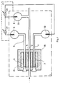
- FIG. 1 shows a measuring device which consists of an integrated ion-selectively permeable element Arrangement and consists of three reference electrodes and contains a measuring cell used to measure the pH.
- the measuring cell 1 there is an ion-selective element 5, which is a microcapillary formed from a pH-sensitive glass, via the sample solution 2 with the internal electrolyte 33 of the reference electrode 8 on the side of the sample Solution 2 connected.
- an ion-selectively permeable element 6 which is produced in an analogous manner to the ion-selectively permeable element 5.
- This element 6 is connected to the first standard reference electrode 9 via a first pH standard solution 3.
- the ion-selectively permeable element 7 is connected to the second standard reference electrode 10 via a second pH standard solution 4.
- the electrolytic 16 ensures the galvanic connection between the microcapillaries of the ion-selectively permeable elements 5, 6 and 7, which are arranged in the measuring cell 1 and are made of H - ion sensitive glass.
- the elements 5, 6 and 7 form together with the electrolyte an integrated ion-selective permeable element arrangement 19.
- the electronic signal processing unit 21 is connected to the reference electrodes 8, 9 and 10 of the measuring cell 1 in such a way that a first measuring circuit 17 on the first Standard reference electrode 9 and the sample reference electrode 8, and a second measuring circuit 18 is connected to the second standard reference electrode 10 and to the sample reference electrode 8.
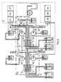
- FIG. 2 shows a measuring arrangement in which Na + - ion- and K + - ion-sensitive measuring cells are present which have integrated sensors and a reference electrode and which are in galvanic connection with one another via the sample solution and are provided with a common sample reference electrode.
- the measuring cell 1 shown in FIG. 2 is Na + - ion-sensitive and completely analogous to the measuring cell according to FIG. 1, with the difference that the microcapillary ion-selectively permeable elements 5, 6 and 7 are not made of H - -lons sensitive, but are made of Na + ion sensitive glass and that the first standard solution 3 and the second standard solution 4 is not an H * ion sensitive solution, but a Na + ion sensitive standard solution.
- the measuring cell 2 contains, in addition to the Na * - ion-sensitive measuring cell 1, a second K - ion-sensitive measuring cell 22, the sample reference electrode of which is identical to the sample reference electrode 8 of the measuring cell 1.
- the measuring cell 22 three microcapillary ion-selectively permeable elements 5, 6 and 7 are in contact with the sample solution 2 and with the first K + ion-sensitive standard solution 11 and the second K * ion-sensitive standard solution 12 formed a single chemically homogeneous electrode body 13.
- the electrode body 13 forms an integrated element arrangement 19 with the ion-selectively permeable elements 5, 6 and 7 formed in it.
- the first K + ion-sensitive standard solution 11 contains the first in the K + ion-sensitive measuring cell 22 K + - standard reference electrode 14 in contact.
- the second K + ion sensitive standard solution 12 is in touch connection with the second K + standard reference electrode 15.
- the Na - ion-sensitive measuring cell 1 is connected via the sample reference electrode 8 as well as via the standard reference electrodes 9 and 10 to the input of the Na + ion measuring amplifier 25 of the electronic processing unit 21, the output of which is connected to a computing unit 26 a display unit is connected (for displaying the Na + ion concentration).
- the K + ion-sensitive measuring cell 22 is connected via the sample reference electrode 8, and also via the K + ion-sensitive standard reference electrodes 14 and 15 to the input of the measuring amplifier of the electronic signal processing unit 21, whose output is connected to the display unit 30 via the arithmetic unit (for the display of the clone concentration).
- sample solution 2 is connected to the peristaltic pump 20 and the standard solutions 11, 12, 3 and 4 are connected in series with the liquid conveyors 23, 24, 31 and 32.
- the H - ion-sensitive measuring cell 1 has ion-selectively permeable elements 5, 6 and 7, which are practically equipotential because the electrolyte 16 causes a galvanic connection between them.
- the elements 5, 6 and 7 are constructed in chemical and mechanical terms so that both their design and their behavior are completely the same.
- the standard potential that forms and the response function steepness characteristic of the sensitivity (“slope •) are essentially the same.
- the voltage measured between two selected electrodes of the sample reference electrode and the standard reference electrodes 9, 10 is practically independent of the standard potentials which have arisen on the elements 5, 7 and 6, and also of their undesired changes.
- the magnitude of the electromotive force measured between the standard reference electrodes 9 and 10 contains the information of the response function steepness (“slope •), that of the sensitivity of the elements 5, 6 and 7 corresponds, provided that the pH values of the first H - ion sensitive standard solution 3 and the second H - ion sensitive standard solution 4 are different from each other.
- the pH value can be calculated by measuring the voltage between the reference electrodes 8, 9 and 10 of the measuring cell by measuring any two voltage values, that this value from that occurring on the elements or electrodes 5, 6 and 7 Standard potential does not depend, and that it is also not dependent on the current value of the response function steepness ("slope"), which is characteristic of the sensitivity, so that the changes in the course of the measurement, which caused measurement errors before the invention was created, do not occur in the method according to the invention Show effects.
- slope response function steepness
- U A1 the voltage measured during the adjustment between the sample electrode 8 and the first standard reference electrode if the element 5 is filled with the first ion-sensitive or pH standard solution 3,
- U B2 the voltage obtained during the adaptation between the sample reference electrode 8 and the second standard reference electrode 10 if the element 5 is filled with the second H + ion-sensitive or pH standard solution 4.
- the required frequency of adaptation is not determined by the elements 5, 6 and 7, but only by the reference electrodes 8, 9 and 10 or by the stability of the reference potentials that appear on them.
- the circuit arrangement according to FIG. 2 works as follows:
- the Na + ion-sensitive measuring cell 1 and the K + - ion-sensitive measuring cell 22 are designed in such a way that two voltages (U Ax ; U Bx ) are measured on these cells in the sense of FIG. 3 and are used in the calculation according to the above function, the pNa value or the pK value of the pattern is obtained.
- the calculated measurement result depends practically neither on the standard potential of the ion-selectively permeable elements, nor on the current value of the response function steepness, so that the measurement result is independent of the changes during the measurement.
- the element body 13 does not contain an electrolyte solution because the galvanic connection between the elements 5, 6 and 7 is ensured by their own material.
- the peristaltic pump 20 enables continuous measurement, etc. by means of the sample solution introduced into the flow.
- the disturbing effect of the flow potentials can be eliminated in that the liquid conveyors 23, 24, 31 and 32 move the standard solutions 3, 4, 11 and 12 at a similar speed as the sample solution flows.
- the interference effects of the diffusion potentials are eliminated in such a way that the internal electrolytes of the reference electrodes 9, 10, 14 and 15 are provided with the standard solutions 3, 4, 11 and 12, the composition of the internal electrolyte 33 of the sample reference electrode 8 with regard to the general composition of the. measuring sample solution is similar.
- the operating person does not have the task of calculating the values sought, which are characteristic of the sample solution, from the measured voltage values, because these adapt the computing units 26 and 29 from the measured and stored values U A1 and U B2 be calculated.
- the arithmetic units not only calculate the pNa values and the pK values, but also the concentration values directly:
Claims (11)
Priority Applications (1)
| Application Number | Priority Date | Filing Date | Title |
|---|---|---|---|
| AT82102014T ATE39026T1 (de) | 1981-03-13 | 1982-03-12 | Elektroanalytische messanordnung. |
Applications Claiming Priority (2)
| Application Number | Priority Date | Filing Date | Title |
|---|---|---|---|
| HU8181639A HU181287B (en) | 1981-03-13 | 1981-03-13 | Electroanalytic measuring arrangement |
| HU63981 | 1981-03-13 |
Publications (3)
| Publication Number | Publication Date |
|---|---|
| EP0060533A2 EP0060533A2 (fr) | 1982-09-22 |
| EP0060533A3 EP0060533A3 (en) | 1985-01-09 |
| EP0060533B1 true EP0060533B1 (fr) | 1988-11-30 |
Family
ID=10950588
Family Applications (1)
| Application Number | Title | Priority Date | Filing Date |
|---|---|---|---|
| EP82102014A Expired EP0060533B1 (fr) | 1981-03-13 | 1982-03-12 | Appareil d'analyse électrochimique |
Country Status (12)
| Country | Link |
|---|---|
| US (1) | US4440619A (fr) |
| EP (1) | EP0060533B1 (fr) |
| JP (1) | JPS57161546A (fr) |
| AT (1) | ATE39026T1 (fr) |
| BR (1) | BR8201284A (fr) |
| DD (1) | DD202213A5 (fr) |
| DE (1) | DE3279252D1 (fr) |
| DK (1) | DK95682A (fr) |
| HU (1) | HU181287B (fr) |
| PL (1) | PL136836B1 (fr) |
| SU (1) | SU1333244A3 (fr) |
| YU (1) | YU53282A (fr) |
Families Citing this family (8)
| Publication number | Priority date | Publication date | Assignee | Title |
|---|---|---|---|---|
| HU180405B (en) * | 1981-03-26 | 1983-03-28 | Nii Ex I Avtomobil Elektroobor | Device for individual feeding winding units to winding machines |
| JPH0736274Y2 (ja) * | 1987-05-15 | 1995-08-16 | ベックマン インスツルメンツ インコーポレーテッド | 改良フローセル |
| US5502388A (en) * | 1993-02-04 | 1996-03-26 | Hoechst Aktiengesellschaft | Method of measuring the pH value of a test solution with glass-electrode measuring cells and of simultaneously calibrating the measuring cells |
| DE102004015084A1 (de) * | 2004-01-21 | 2005-08-18 | Winfried Schellbach | Verfahren zum Bestimmen eines pH-Wertes und pH-Messelektrode |
| US8398835B2 (en) * | 2006-03-23 | 2013-03-19 | Hach Company | Unitary ionic probe |
| US8551311B2 (en) | 2006-09-06 | 2013-10-08 | Hach Company | Ionic probe |
| CN101828107B (zh) * | 2007-10-19 | 2014-07-23 | 哈赫公司 | 多电极离子探头 |
| KR100974564B1 (ko) * | 2008-05-22 | 2010-08-06 | 한국원자력연구원 | 자동 교정 기능을 가지는 기준전극 및 이를 이용한전기화학적 전위 자동보정 장치 |
Family Cites Families (4)
| Publication number | Priority date | Publication date | Assignee | Title |
|---|---|---|---|---|
| US3539455A (en) * | 1965-10-08 | 1970-11-10 | Leland C Clark Jr | Membrane polarographic electrode system and method with electrochemical compensation |
| US3838034A (en) * | 1968-04-22 | 1974-09-24 | Gen Electric | Apparatus for detection of catalase-containing bacteria |
| JPS54119787A (en) * | 1978-03-10 | 1979-09-17 | Olympus Optical Co | Ionic electrode measuring method and its device |
| US4318885A (en) * | 1979-09-10 | 1982-03-09 | Olympus Optical Co., Ltd. | Liquid treating device for chemical analysis apparatus |
-
1981
- 1981-03-13 HU HU8181639A patent/HU181287B/hu not_active IP Right Cessation
-
1982
- 1982-03-01 US US06/353,289 patent/US4440619A/en not_active Expired - Fee Related
- 1982-03-04 DK DK95682A patent/DK95682A/da not_active Application Discontinuation
- 1982-03-10 DD DD82238038A patent/DD202213A5/de not_active IP Right Cessation
- 1982-03-10 BR BR8201284A patent/BR8201284A/pt unknown
- 1982-03-11 YU YU00532/82A patent/YU53282A/xx unknown
- 1982-03-11 PL PL1982235401A patent/PL136836B1/pl unknown
- 1982-03-12 JP JP57039283A patent/JPS57161546A/ja active Pending
- 1982-03-12 EP EP82102014A patent/EP0060533B1/fr not_active Expired
- 1982-03-12 SU SU823409905A patent/SU1333244A3/ru active
- 1982-03-12 DE DE8282102014T patent/DE3279252D1/de not_active Expired
- 1982-03-12 AT AT82102014T patent/ATE39026T1/de not_active IP Right Cessation
Also Published As
| Publication number | Publication date |
|---|---|
| HU181287B (en) | 1983-06-28 |
| DK95682A (da) | 1982-09-14 |
| EP0060533A2 (fr) | 1982-09-22 |
| JPS57161546A (en) | 1982-10-05 |
| EP0060533A3 (en) | 1985-01-09 |
| US4440619A (en) | 1984-04-03 |
| SU1333244A3 (ru) | 1987-08-23 |
| DD202213A5 (de) | 1983-08-31 |
| PL136836B1 (en) | 1986-03-31 |
| YU53282A (en) | 1984-12-31 |
| BR8201284A (pt) | 1983-01-18 |
| DE3279252D1 (en) | 1989-01-05 |
| PL235401A1 (fr) | 1982-10-25 |
| ATE39026T1 (de) | 1988-12-15 |
Similar Documents
| Publication | Publication Date | Title |
|---|---|---|
| EP0065202B1 (fr) | Procédé pour la mesure de concentrations ioniques | |
| DE3445164C2 (fr) | ||
| DE69727485T2 (de) | Elektrochemischer sensor | |
| DE3537919A1 (de) | Anordnung zur stabilisierung einer gas-bezugselektrode | |
| DE2224703B2 (de) | Elektrochemische Meßeinrichtung | |
| DE102013109105A1 (de) | Messanordnung | |
| DE102018128885A1 (de) | Glaselektrode | |
| DE102011086591A1 (de) | Elektrochemische Halbzelle, elektrochemischer Sensor und Verfahren zur Messung mindestens einer Eigenschaft einer Messgröße mit einem elektrochemischen Sensor | |
| DE102019120446A1 (de) | Verfahren zur Korrektur von zwei Messwerten von jeweils verschiedener Analysenmessgeräte sowie Messstelle zum Ausführen des Verfahrens | |
| DE102012101254A1 (de) | Messanordnung und Verfahren zur Erfassung einer Analytkonzentration in einem Messmedium | |
| EP0060533B1 (fr) | Appareil d'analyse électrochimique | |
| DE3146066C2 (fr) | ||
| EP0581081A1 (fr) | Méthode pour la détermination des péracides | |
| EP0247535B1 (fr) | Electrode de référence pour la mesure de l'activité ionique, en particulier pour la mesure de pH | |
| DE4225904A1 (de) | Sensor fuer elektrochemische messungen | |
| EP0262582B1 (fr) | Procédé pour la détermination du rapport des concentrations en ions lithium et sodium et appareil pour l'utilisation du procédé | |
| EP0062250B1 (fr) | Procédé d'analyse électrochimique avec compensation d'erreur et appareil pour l'utilisation du procédé | |
| DE4029321C2 (fr) | ||
| EP0780685A1 (fr) | Capteur ampérométrique à deux électrodes, en particulier pour le peroxyde d'hydrogène | |
| DE102005013849B4 (de) | Verfahren und Vorrichtung zur Bestimmung eines pH-Wertes | |
| DE2927346A1 (de) | Verfahren zum bestimmen des membranverschmutzungsgrades einer elektrochemischen zelle | |
| DE19901041B4 (de) | Vorrichtung und Verfahren zum Messen von Meßgrößen in einer Flüssigkeit | |
| DE102019133805A1 (de) | Verfahren zur Messwertkorrektur sowie ein Sensorsystem mit zwei verschiedenen pH-Sensoren | |
| DE102018208482A1 (de) | Potentiometrische Messkette und Verfahren zur pH-Wert-Bestimmung | |
| DE4335241A1 (de) | Verfahren zur kontinuierlichen Analyse von Bestandteilen einer Flüssigkeit |
Legal Events
| Date | Code | Title | Description |
|---|---|---|---|
| PUAI | Public reference made under article 153(3) epc to a published international application that has entered the european phase |
Free format text: ORIGINAL CODE: 0009012 |
|
| AK | Designated contracting states |
Kind code of ref document: A2 Designated state(s): AT CH DE FR GB SE Designated state(s): AT CH DE FR GB SE |
|
| PUAL | Search report despatched |
Free format text: ORIGINAL CODE: 0009013 |
|
| AK | Designated contracting states |
Kind code of ref document: A3 Designated state(s): AT CH DE FR GB LI SE |
|
| 17P | Request for examination filed |
Effective date: 19850509 |
|
| 17Q | First examination report despatched |
Effective date: 19861113 |
|
| GRAA | (expected) grant |
Free format text: ORIGINAL CODE: 0009210 |
|
| AK | Designated contracting states |
Kind code of ref document: B1 Designated state(s): AT CH DE FR GB LI SE |
|
| REF | Corresponds to: |
Ref document number: 39026 Country of ref document: AT Date of ref document: 19881215 Kind code of ref document: T |
|
| GBT | Gb: translation of ep patent filed (gb section 77(6)(a)/1977) | ||
| REF | Corresponds to: |
Ref document number: 3279252 Country of ref document: DE Date of ref document: 19890105 |
|
| ET | Fr: translation filed | ||
| PGFP | Annual fee paid to national office [announced via postgrant information from national office to epo] |
Ref country code: AT Payment date: 19890310 Year of fee payment: 8 |
|
| PGFP | Annual fee paid to national office [announced via postgrant information from national office to epo] |
Ref country code: SE Payment date: 19890317 Year of fee payment: 8 |
|
| PGFP | Annual fee paid to national office [announced via postgrant information from national office to epo] |
Ref country code: FR Payment date: 19890323 Year of fee payment: 8 |
|
| PGFP | Annual fee paid to national office [announced via postgrant information from national office to epo] |
Ref country code: GB Payment date: 19890331 Year of fee payment: 8 Ref country code: CH Payment date: 19890331 Year of fee payment: 8 |
|
| PGFP | Annual fee paid to national office [announced via postgrant information from national office to epo] |
Ref country code: DE Payment date: 19890413 Year of fee payment: 8 |
|
| PLBE | No opposition filed within time limit |
Free format text: ORIGINAL CODE: 0009261 |
|
| STAA | Information on the status of an ep patent application or granted ep patent |
Free format text: STATUS: NO OPPOSITION FILED WITHIN TIME LIMIT |
|
| 26N | No opposition filed | ||
| PG25 | Lapsed in a contracting state [announced via postgrant information from national office to epo] |
Ref country code: GB Effective date: 19900312 Ref country code: AT Effective date: 19900312 |
|
| PG25 | Lapsed in a contracting state [announced via postgrant information from national office to epo] |
Ref country code: SE Effective date: 19900313 |
|
| PG25 | Lapsed in a contracting state [announced via postgrant information from national office to epo] |
Ref country code: LI Effective date: 19900331 Ref country code: CH Effective date: 19900331 |
|
| GBPC | Gb: european patent ceased through non-payment of renewal fee | ||
| PG25 | Lapsed in a contracting state [announced via postgrant information from national office to epo] |
Ref country code: FR Effective date: 19901130 |
|
| REG | Reference to a national code |
Ref country code: CH Ref legal event code: PL |
|
| PG25 | Lapsed in a contracting state [announced via postgrant information from national office to epo] |
Ref country code: DE Effective date: 19901201 |
|
| REG | Reference to a national code |
Ref country code: FR Ref legal event code: ST |
|
| EUG | Se: european patent has lapsed |
Ref document number: 82102014.6 Effective date: 19910110 |