EP0060533B1 - Electrochemical analyser - Google Patents
Electrochemical analyser Download PDFInfo
- Publication number
- EP0060533B1 EP0060533B1 EP82102014A EP82102014A EP0060533B1 EP 0060533 B1 EP0060533 B1 EP 0060533B1 EP 82102014 A EP82102014 A EP 82102014A EP 82102014 A EP82102014 A EP 82102014A EP 0060533 B1 EP0060533 B1 EP 0060533B1
- Authority
- EP
- European Patent Office
- Prior art keywords
- ion
- standard
- measuring device
- solution
- electroanalytical
- Prior art date
- Legal status (The legal status is an assumption and is not a legal conclusion. Google has not performed a legal analysis and makes no representation as to the accuracy of the status listed.)
- Expired
Links
- 230000000694 effects Effects 0.000 claims abstract description 8
- 239000000203 mixture Substances 0.000 claims abstract description 6
- 239000012086 standard solution Substances 0.000 claims description 27
- 239000012488 sample solution Substances 0.000 claims description 14
- 239000003792 electrolyte Substances 0.000 claims description 8
- 229910001415 sodium ion Inorganic materials 0.000 claims description 8
- 238000012545 processing Methods 0.000 claims description 7
- 239000011521 glass Substances 0.000 claims description 4
- 150000002500 ions Chemical class 0.000 claims 10
- 239000012085 test solution Substances 0.000 claims 7
- 239000000470 constituent Substances 0.000 claims 1
- 239000000126 substance Substances 0.000 abstract description 2
- 239000007789 gas Substances 0.000 abstract 1
- 238000005259 measurement Methods 0.000 description 21
- 239000000523 sample Substances 0.000 description 17
- 229910001414 potassium ion Inorganic materials 0.000 description 8
- 238000005316 response function Methods 0.000 description 5
- 238000004458 analytical method Methods 0.000 description 4
- 238000000034 method Methods 0.000 description 4
- 230000035945 sensitivity Effects 0.000 description 4
- 230000006978 adaptation Effects 0.000 description 3
- 239000000463 material Substances 0.000 description 3
- 239000000243 solution Substances 0.000 description 3
- 238000004364 calculation method Methods 0.000 description 2
- 230000001419 dependent effect Effects 0.000 description 2
- 238000013461 design Methods 0.000 description 2
- 238000009792 diffusion process Methods 0.000 description 2
- 239000012530 fluid Substances 0.000 description 2
- 239000007788 liquid Substances 0.000 description 2
- 239000012528 membrane Substances 0.000 description 2
- 230000002572 peristaltic effect Effects 0.000 description 2
- 230000036755 cellular response Effects 0.000 description 1
- 238000011109 contamination Methods 0.000 description 1
- 238000011161 development Methods 0.000 description 1
- 230000018109 developmental process Effects 0.000 description 1
- 239000008151 electrolyte solution Substances 0.000 description 1
- 230000006870 function Effects 0.000 description 1
- 238000004519 manufacturing process Methods 0.000 description 1
- 230000009131 signaling function Effects 0.000 description 1
Images

Classifications
-
- G—PHYSICS
- G01—MEASURING; TESTING
- G01N—INVESTIGATING OR ANALYSING MATERIALS BY DETERMINING THEIR CHEMICAL OR PHYSICAL PROPERTIES
- G01N27/00—Investigating or analysing materials by the use of electric, electrochemical, or magnetic means
- G01N27/26—Investigating or analysing materials by the use of electric, electrochemical, or magnetic means by investigating electrochemical variables; by using electrolysis or electrophoresis
- G01N27/416—Systems
- G01N27/4163—Systems checking the operation of, or calibrating, the measuring apparatus
- G01N27/4165—Systems checking the operation of, or calibrating, the measuring apparatus for pH meters
Definitions
- the invention relates to an electroanalytical measuring device with at least one measuring cell and an electronic signal processing unit for determining the ion activity of solutions that are at rest or flowing.
- the measured variable e.g. membrane potential
- a conventionally designed electroanalytical element e.g. on an ion-selective membrane
- the measured variable is not only determined by the corresponding electrochemical parameters of the measured sample, but is also influenced by the material quality, the geometry and, if appropriate, the degree of contamination of the base material of the ion-selectively permeable element.
- the age of the ion-selectively permeable element (calculated from the manufacture), etc. also plays a role.
- the measured variable arises in the course of the measurement as a result of the above factors. It follows that from the electrochemical parameter change to be measured (e.g. from the decrease or increase in the ion concentration) the change in the measured variable cannot be distinguished by the state of the ion-selectively permeable element due to the above-mentioned interference effects.
- the accuracy of the measurements depends on how often one or more adjustments have to be made. In the case of precision measurements with a control character, the adjustment must be carried out in some way before the measurement. If the time taken to flush the measuring cell is considered, the result is that the total time of the analysis - in the case of the use of two standard fluids - often corresponds to five times the effective measuring time. Although this "adjustment by a point, which is widely used in electrical analysis, can reduce this time by about half, there is an unavoidable error caused by the change in the slope of the measuring cell response signal function (the so-called" slope •) during the Measurement is caused.
- the object of the invention is to determine in an electroanalytical measuring device of the type mentioned the characteristic parameters of the individual properties of the ion-selectively permeable element which is arranged in the electroanalytical measuring cell (e.g. standard potential, steepness of the response function) or the changes thereof Track parameters during the measurement and compensate in this way.
- the characteristic parameters of the individual properties of the ion-selectively permeable element which is arranged in the electroanalytical measuring cell e.g. standard potential, steepness of the response function
- the measuring arrangement according to the invention offers the following essential advantages, which are summarized in the following way:
- the adjustment operation can be carried out in the course of the measurement.
- the measurement result becomes completely independent of those fault errors which result from the changes in the electrochemical parameters of the ion-selectively permeable element.
- the application of the invention greatly reduces the disruptive effect of the diffusion potentials.
- Continuous or step-by-step measurements can be carried out with significantly higher accuracy compared to the previous methods.
- the total time of the analysis is shortened significantly.
- An electroanalytical measuring device which in the sense of the invention consists of an integrated ion-selectively permeable element arrangement and a plurality of reference electrodes, is explained below using two exemplary embodiments with reference to FIGS. 1 to 3.
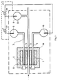
- FIG. 1 shows a measuring device which consists of an integrated ion-selectively permeable element Arrangement and consists of three reference electrodes and contains a measuring cell used to measure the pH.
- the measuring cell 1 there is an ion-selective element 5, which is a microcapillary formed from a pH-sensitive glass, via the sample solution 2 with the internal electrolyte 33 of the reference electrode 8 on the side of the sample Solution 2 connected.
- an ion-selectively permeable element 6 which is produced in an analogous manner to the ion-selectively permeable element 5.
- This element 6 is connected to the first standard reference electrode 9 via a first pH standard solution 3.
- the ion-selectively permeable element 7 is connected to the second standard reference electrode 10 via a second pH standard solution 4.
- the electrolytic 16 ensures the galvanic connection between the microcapillaries of the ion-selectively permeable elements 5, 6 and 7, which are arranged in the measuring cell 1 and are made of H - ion sensitive glass.
- the elements 5, 6 and 7 form together with the electrolyte an integrated ion-selective permeable element arrangement 19.
- the electronic signal processing unit 21 is connected to the reference electrodes 8, 9 and 10 of the measuring cell 1 in such a way that a first measuring circuit 17 on the first Standard reference electrode 9 and the sample reference electrode 8, and a second measuring circuit 18 is connected to the second standard reference electrode 10 and to the sample reference electrode 8.
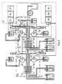
- FIG. 2 shows a measuring arrangement in which Na + - ion- and K + - ion-sensitive measuring cells are present which have integrated sensors and a reference electrode and which are in galvanic connection with one another via the sample solution and are provided with a common sample reference electrode.
- the measuring cell 1 shown in FIG. 2 is Na + - ion-sensitive and completely analogous to the measuring cell according to FIG. 1, with the difference that the microcapillary ion-selectively permeable elements 5, 6 and 7 are not made of H - -lons sensitive, but are made of Na + ion sensitive glass and that the first standard solution 3 and the second standard solution 4 is not an H * ion sensitive solution, but a Na + ion sensitive standard solution.
- the measuring cell 2 contains, in addition to the Na * - ion-sensitive measuring cell 1, a second K - ion-sensitive measuring cell 22, the sample reference electrode of which is identical to the sample reference electrode 8 of the measuring cell 1.
- the measuring cell 22 three microcapillary ion-selectively permeable elements 5, 6 and 7 are in contact with the sample solution 2 and with the first K + ion-sensitive standard solution 11 and the second K * ion-sensitive standard solution 12 formed a single chemically homogeneous electrode body 13.
- the electrode body 13 forms an integrated element arrangement 19 with the ion-selectively permeable elements 5, 6 and 7 formed in it.
- the first K + ion-sensitive standard solution 11 contains the first in the K + ion-sensitive measuring cell 22 K + - standard reference electrode 14 in contact.
- the second K + ion sensitive standard solution 12 is in touch connection with the second K + standard reference electrode 15.
- the Na - ion-sensitive measuring cell 1 is connected via the sample reference electrode 8 as well as via the standard reference electrodes 9 and 10 to the input of the Na + ion measuring amplifier 25 of the electronic processing unit 21, the output of which is connected to a computing unit 26 a display unit is connected (for displaying the Na + ion concentration).
- the K + ion-sensitive measuring cell 22 is connected via the sample reference electrode 8, and also via the K + ion-sensitive standard reference electrodes 14 and 15 to the input of the measuring amplifier of the electronic signal processing unit 21, whose output is connected to the display unit 30 via the arithmetic unit (for the display of the clone concentration).
- sample solution 2 is connected to the peristaltic pump 20 and the standard solutions 11, 12, 3 and 4 are connected in series with the liquid conveyors 23, 24, 31 and 32.
- the H - ion-sensitive measuring cell 1 has ion-selectively permeable elements 5, 6 and 7, which are practically equipotential because the electrolyte 16 causes a galvanic connection between them.
- the elements 5, 6 and 7 are constructed in chemical and mechanical terms so that both their design and their behavior are completely the same.
- the standard potential that forms and the response function steepness characteristic of the sensitivity (“slope •) are essentially the same.
- the voltage measured between two selected electrodes of the sample reference electrode and the standard reference electrodes 9, 10 is practically independent of the standard potentials which have arisen on the elements 5, 7 and 6, and also of their undesired changes.
- the magnitude of the electromotive force measured between the standard reference electrodes 9 and 10 contains the information of the response function steepness (“slope •), that of the sensitivity of the elements 5, 6 and 7 corresponds, provided that the pH values of the first H - ion sensitive standard solution 3 and the second H - ion sensitive standard solution 4 are different from each other.
- the pH value can be calculated by measuring the voltage between the reference electrodes 8, 9 and 10 of the measuring cell by measuring any two voltage values, that this value from that occurring on the elements or electrodes 5, 6 and 7 Standard potential does not depend, and that it is also not dependent on the current value of the response function steepness ("slope"), which is characteristic of the sensitivity, so that the changes in the course of the measurement, which caused measurement errors before the invention was created, do not occur in the method according to the invention Show effects.
- slope response function steepness
- U A1 the voltage measured during the adjustment between the sample electrode 8 and the first standard reference electrode if the element 5 is filled with the first ion-sensitive or pH standard solution 3,
- U B2 the voltage obtained during the adaptation between the sample reference electrode 8 and the second standard reference electrode 10 if the element 5 is filled with the second H + ion-sensitive or pH standard solution 4.
- the required frequency of adaptation is not determined by the elements 5, 6 and 7, but only by the reference electrodes 8, 9 and 10 or by the stability of the reference potentials that appear on them.
- the circuit arrangement according to FIG. 2 works as follows:
- the Na + ion-sensitive measuring cell 1 and the K + - ion-sensitive measuring cell 22 are designed in such a way that two voltages (U Ax ; U Bx ) are measured on these cells in the sense of FIG. 3 and are used in the calculation according to the above function, the pNa value or the pK value of the pattern is obtained.
- the calculated measurement result depends practically neither on the standard potential of the ion-selectively permeable elements, nor on the current value of the response function steepness, so that the measurement result is independent of the changes during the measurement.
- the element body 13 does not contain an electrolyte solution because the galvanic connection between the elements 5, 6 and 7 is ensured by their own material.
- the peristaltic pump 20 enables continuous measurement, etc. by means of the sample solution introduced into the flow.
- the disturbing effect of the flow potentials can be eliminated in that the liquid conveyors 23, 24, 31 and 32 move the standard solutions 3, 4, 11 and 12 at a similar speed as the sample solution flows.
- the interference effects of the diffusion potentials are eliminated in such a way that the internal electrolytes of the reference electrodes 9, 10, 14 and 15 are provided with the standard solutions 3, 4, 11 and 12, the composition of the internal electrolyte 33 of the sample reference electrode 8 with regard to the general composition of the. measuring sample solution is similar.
- the operating person does not have the task of calculating the values sought, which are characteristic of the sample solution, from the measured voltage values, because these adapt the computing units 26 and 29 from the measured and stored values U A1 and U B2 be calculated.
- the arithmetic units not only calculate the pNa values and the pK values, but also the concentration values directly:
Abstract
Description
Die Erfindung betrifft eine elektroanalytische Meßvorrichtung mit mindestens einer Meßzelle und einer elektronischen Signalbearbeitungseinheit zur Bestimmung der lonenaktivität von in Ruhe befindlichen oder strömenden Lösungen.The invention relates to an electroanalytical measuring device with at least one measuring cell and an electronic signal processing unit for determining the ion activity of solutions that are at rest or flowing.
Es ist bekannt, daß die Meßgröße (z. B. Membranpotential), gemessen mit einem herkömmlicherweise gestalteten elektroanalytischen Element (z. B. an einer ionselektiven Membrane) nicht nur durch die entsprechenden elektrochemischen Parameter der gemessenen Probe bestimmt wird, sondern auch beeinflußt wird durch die Materialqualität, die Geometrie, gegebenenfalls das Maß der Verunreinigung des Grundmaterials des ionenselektiv permeablen Elementes. Ferner spielt auch das « Alter des ionenselektiv permeablen Elementes (berechnet von der Herstellung), usw. eine Rolle. Infolgedessen entsteht also die Meßgröße im Laufe der Messung als Resultierende der obigen Faktoren. Daraus folgt, daß man aus der zu messenden elektrochemischen Parameterveränderung (z. B. aus der Senkung oder Erhöhung der lonkonzentration) die Meßgrößeänderung durch den Zustand des ionenselektiv permeablen Elementes aufgrund der oben erwähnten Störeffekte nicht unterscheiden kann.It is known that the measured variable (e.g. membrane potential), measured with a conventionally designed electroanalytical element (e.g. on an ion-selective membrane) is not only determined by the corresponding electrochemical parameters of the measured sample, but is also influenced by the material quality, the geometry and, if appropriate, the degree of contamination of the base material of the ion-selectively permeable element. The age of the ion-selectively permeable element (calculated from the manufacture), etc. also plays a role. As a result, the measured variable arises in the course of the measurement as a result of the above factors. It follows that from the electrochemical parameter change to be measured (e.g. from the decrease or increase in the ion concentration) the change in the measured variable cannot be distinguished by the state of the ion-selectively permeable element due to the above-mentioned interference effects.
Bei herkömmlichen Meßverfahren (Kalibrierung, Standard-Addition, Konstantionstärke-Einstellung, Steilheit-Programmierung, usw.) besteht nicht das Bestreben, die Bestimmung der aus diesen Störungen stammenden Fehlsignale durchzuführen. (Siehe z. B. Havas : lon- und molekulselektive Elektrode in biologischen Systemen, Neue Ergebnisse der Chemie/Akademischer Verlag, 1980, Seiten 80-87). Bei den bisher bekannten Verfahren wird vielmehr die zu bestimmende Probe mit einem oder mehreren Fluiden bekannter Zusammensetzung (Standardlösung oder Gas) über die entsprechenden elektrochemischen Parameter verglichen. Das bedeutet, daß vor der Messung die elektronischen Parameter des Meßgerätes und die elektrochemischen Parameter der Meßzelle durch entsprechende Betätigungsorgane verglichen bzw. abgestimmt werden müssen. Diese Operation wird allgemein als Anpassung bezeichnet.With conventional measuring methods (calibration, standard addition, constant strength setting, slope programming, etc.) there is no attempt to determine the false signals originating from these disturbances. (See, for example, Havas: lon- and molecule-selective electrode in biological systems, New Results of Chemistry / Akademischer Verlag, 1980, pages 80-87). Rather, in the previously known methods, the sample to be determined is compared with one or more fluids of known composition (standard solution or gas) using the corresponding electrochemical parameters. This means that the electronic parameters of the measuring device and the electrochemical parameters of the measuring cell have to be compared or coordinated by appropriate actuators before the measurement. This operation is commonly referred to as adjustment.
Wegen der unkontrollierbaren Unbestimmbarkeiten der Erscheinung dieser Störungen hängt die Genauigkeit der Messungen davon ab, wie oft eine Anpassung oder mehrere Anpassungen vorgenommen werden müssen. Bei Präzisionsmessungen mit Kontroll-Charakter muß vor der Messung die Anpassung in irgendwelcher Weise durchgeführt werden. Wird diejenige Zeit betrachtet, die zum Durchspülen der Meßzelle aufgewendet werden muß, so ergibt sich, daß die Gesamtzeit der Analyse - im Falle der Anwendung von zwei Standardfluidenhäufig dem Fünffachen der effektiven Meßzeit entspricht. Obwohl durch die in der Elektroanalyse in breitem Maße verwendete « Anpassung durch einen Punkt diese Zeit ungefähr auf die Hälfte gesenkt werden kann, ergibt sich aber ein unvermeidbarer Fehler, der durch die Änderung der Steilheit der Meßzellenansprechsignalfunktion (das sog. « slope •) während der Messung verursacht wird.Because of the uncontrollable indeterminability of the appearance of these disturbances, the accuracy of the measurements depends on how often one or more adjustments have to be made. In the case of precision measurements with a control character, the adjustment must be carried out in some way before the measurement. If the time taken to flush the measuring cell is considered, the result is that the total time of the analysis - in the case of the use of two standard fluids - often corresponds to five times the effective measuring time. Although this "adjustment by a point, which is widely used in electrical analysis, can reduce this time by about half, there is an unavoidable error caused by the change in the slope of the measuring cell response signal function (the so-called" slope •) during the Measurement is caused.
Aufgrund der obigen Ausführungen ist evident, daß die Gesamtzeit von Präzisierungsanalysen - wegen der zwangsläufig zwischen den effektiven Messungen eingefügten Anpassungsoperationen - äußerst lang ist. Kontinuierlich und gleichzeitig sind genügend genaue Messungen nicht möglich, da die Art und Weise des Aufbaues der Meßzellen die Bestimmung der Fehlersignale im Laufe der Messung nicht ermöglicht, wodurch eine Anpassung im Laufe der Messung nicht durchgeführt werden kann.Based on the above, it is evident that the total time of precision analysis is extremely long due to the adjustment operations necessarily inserted between the effective measurements. Sufficiently precise measurements are not possible continuously and at the same time, since the manner in which the measuring cells are constructed does not make it possible to determine the error signals during the measurement, so that an adaptation cannot be carried out during the measurement.
Aufgabe der Erfindung ist es, bei einer elektroanalytischer Meßvorrichtung der eingangs genannten Art die charakterischen Parameter der individuellen Eigenschaften des ionenselektiv permeablen Elementes, das in der elektroanalytischen Meßzelle angeordnet ist (z. B. Standardpotential, Steilheit der Antwortfunktion) zu ermitteln bzw. die Änderungen dieser Parameter auch im Laufe der Messung zu verfolgen und auf diese Weise zu kompensieren.The object of the invention is to determine in an electroanalytical measuring device of the type mentioned the characteristic parameters of the individual properties of the ion-selectively permeable element which is arranged in the electroanalytical measuring cell (e.g. standard potential, steepness of the response function) or the changes thereof Track parameters during the measurement and compensate in this way.
Diese Aufgabe wird erfindungsgemäß durch die Merkmale des Anspruchs 1 gelöst. Die Meßanordnung gemäß der Erfindung bietet die nachstehenden wesentlichen Vorteile, die in folgender Weise zusammengefaßt werden :This object is achieved by the features of claim 1. The measuring arrangement according to the invention offers the following essential advantages, which are summarized in the following way:
Es wird die Beobachtung der elektrochemischen Parameter des ionenselektiv permeablen Elementes im Laufe der Messung ermöglicht.The observation of the electrochemical parameters of the ion-selective permeable element is made possible in the course of the measurement.
Durch Anwendung der Erfindung kann die Anpassungsoperation im Verlaufe der Messung durchgeführt werden.By using the invention, the adjustment operation can be carried out in the course of the measurement.
Das Meßergebnis wird völlig unabhängig von denjenigen Störungsfehlern, die aus den Veränderungen der elektrochemischen Parameter des ionenselektiv permeablen Elementes stammen.The measurement result becomes completely independent of those fault errors which result from the changes in the electrochemical parameters of the ion-selectively permeable element.
Der Strömungspotentialfehler wird völlig beseitigt.The flow potential error is completely eliminated.
Die Anwendung der Erfindung setzt den störenden Effekt der Diffusionspotentiale in großem Maße herab.The application of the invention greatly reduces the disruptive effect of the diffusion potentials.
Kontinuierliche oder stufenweise Meßvorgänge können im Vergleich mit den bisherigen Methoden mit bedeutend höherer Genauigkeit durchgeführt werden.Continuous or step-by-step measurements can be carried out with significantly higher accuracy compared to the previous methods.
Die Gesamtzeit der Analyse wird bedeutend abgekürzt.The total time of the analysis is shortened significantly.
Vorteilhafte Weiterbildungen der Erfindung sind durch die abhängigen Ansprüche gekennzeichnet. Eine elektroanalytische Meßvorrichtung, die im Sinne der Erfindung aus einer integrierten ionenselektiv permeablen Element-Anordnung und aus mehreren Bezugselektroden besteht, wird nachstehend an zwei Ausführungsbeispielen anhand der Figuren 1 bis 3 erläutert.Advantageous developments of the invention are characterized by the dependent claims. An electroanalytical measuring device, which in the sense of the invention consists of an integrated ion-selectively permeable element arrangement and a plurality of reference electrodes, is explained below using two exemplary embodiments with reference to FIGS. 1 to 3.
Fig. 1 zeigt eine Meßvorrichtung die aus einer integrierten ionenselektiv permeablen Element-Anordnung und aus drei Bezugselektroden besteht und eine zur Messung des pH-Wertes dienende Meßzelle beinhaltet.1 shows a measuring device which consists of an integrated ion-selectively permeable element Arrangement and consists of three reference electrodes and contains a measuring cell used to measure the pH.
Wie es aus Fig. 1 hervorgeht, ist in der Meßzelle 1 ein ionenselektives Element 5, das eine aus einem pH-empfindlichen Glas ausgebildete Mikrokapillare ist, über die Proben-Lösung 2 mit dem inneren Elektrolyt 33 der Bezugselektrode 8 an der Seite der Proben-Lösung 2 verbunden. In der Meßzelle 1 ist auch ein ionenselektiv permeables Element 6, angeordnet, das in analoger Weise zum ionenselektiv permeablen Element 5 hergestellt ist. Dieses Element 6 ist über eine erste pH-Standardlösung 3 mit der ersten Standard-Bezugselektrode 9 verbunden. Ähnlich zu diesem ist das ionenselektiv permeable Element 7 über eine zweite pH-Standardlösung 4 mit der zweiten Standard-Bezugselektrode 10 verbunden. Die galvanische Verbindung zwischen den in der Meßzelle 1 angeordneten, aus H--lonen- empfindlichem Glas ausgebildeten Mikrokapillaren der ionenselektiv permeablen Elemente 5, 6 und 7 ist durch den Elektrolyt 16 gesichert. Die Elemente 5, 6 und 7 bilden mit dem Elektrolyt zusammen eine integrierte ionenselektiv permeable Element-Anordnung 19. Die elektronische Signalverarbeitungseinheit 21 ist an den Bezugselektroden 8, 9 und 10 der Meßzelle 1 in der Weise angeschlossen, daß ein erster Meßkreis 17 an der ersten Standard-Bezugselektrode 9 und an der Proben-Bezugselektrode 8, und ein zweiter Meßkreis 18 an der zweiten Standard-Bezugselektrode 10 und an der Proben-Bezugselektrode 8 angeschlossen ist.As can be seen from FIG. 1, in the measuring cell 1 there is an ion-
Fig. 2 zeigt eine Meßanordnung, bei welcher Na+-lonen- und K+-lonen-empfindliche - miteinander über die Proben-Lösung in galvanischer Verbindung stehende und mit einer gemeinsamen Proben-Bezugselektrode versehene - integrierte Fühler und Bezugselektrode aufweisende Meßzellen vorhanden sind.2 shows a measuring arrangement in which Na + - ion- and K + - ion-sensitive measuring cells are present which have integrated sensors and a reference electrode and which are in galvanic connection with one another via the sample solution and are provided with a common sample reference electrode.
Die in Fig. 2 dargestellte Meßzelle 1 ist Na+-lonen-empfindlich und zur Meßzelle gemäß Fig. 1 völlig analog ausgebildet, mit dem Unterschied, daß die mikrokapillaren ionenselektiv permeable Elemente 5, 6 und 7 nicht aus H--lonen empfindlichem, sondern aus Na+-lonen empfindlichem Glas hergestellt sind und daß die erste Standardlösung 3 und die zweite Standardlösung 4 keine H*-lonen-empfindliche Lösung, sondern eine Na+-lonen-empfindliche Standard-Lösung ist.The measuring cell 1 shown in FIG. 2 is Na + - ion-sensitive and completely analogous to the measuring cell according to FIG. 1, with the difference that the microcapillary ion-selectively
Die Meßvorrichtung gemäß Fig. 2 enthält außer der Na*-lonen-empfindlichen Meßzelle 1 auch eine zweite K--lonen-empfindliche Meßzelle 22, deren Proben-Bezugselektrode mit der Proben-Bezugselektrode 8 der Meßzelle 1 identisch ist. In der Meßzelle 22 sind drei mit der Proben-Lösung 2 und mit der ersten K+-lonen-empfindlichen-Standardlösung 11 und der zweiten K*-lonen-empfindlichen Standardlösung 12 in Berührung stehende, mikrokapillare ionenselektiv permeable Elemente 5, 6 und 7 aus einem einzigen chemisch-homogen gestalteten Elektroden-Körper 13 ausgebildet. Der Elektroden-Körper 13 bildet mit den in ihm ausgebildeten ionenselektiv permeablen Elementen 5, 6 und 7 eine integrierte Element-Anordnung 19. In der K+-lonen-empfindlichen Meßzelle 22 steht mit der ersten K+-lonen-empfindlichen Standardlösung 11 die erste K+-Standard-Bezugselektrode 14 in Berührung. Ähnlich hierzu ist die zweite K+-lonen-empfindliche Standardlösung 12 mit der zweiten K+ Standard-Bezugselektrode 15 in Berührungsverbindung.2 contains, in addition to the Na * - ion-sensitive measuring cell 1, a second K - ion-sensitive measuring cell 22, the sample reference electrode of which is identical to the
Die Na--lonen-empfindliche Meßzelle 1 ist über die Proben-Bezugselektrode 8 wie auch über die Standard-Bezugselektroden 9 und 10 an den Eingang des Na+-lonen-Meßverstärkers 25 der elektronischen Verarbeitungseinheit 21 angeschlossen, dessen Ausgang über eine Recheneinheit 26 an eine Anzeigeeinheit angeschlossen ist (für die Anzeige der Na+-lonen-Konzentration).The Na - ion-sensitive measuring cell 1 is connected via the
Ähnlich zu dieser Anordnung ist die K+-lonen-empfindliche Meßzelle 22 über die Proben-Bezugselektrode 8, und auch über die K+-lonen-empfindliche Standard-Bezugselektroden 14 und 15 an den Eingang des Meßverstärkers der elektronischen Signalbearbeitungseinheit 21 angeschlossen, dessen Ausgang über die arithmetische Einheit an die Anzeigeeinheit 30 angeschlossen ist (für die Anzeige der K--lonen-Konzentration).Similar to this arrangement, the K + ion-sensitive measuring cell 22 is connected via the
Darüber hinaus ist die Probenlösung 2 mit der peristaltischen Pumpe 20 verbunden und sind die Standardlösungen 11, 12, 3 und 4 in Reihe mit den Flüssigkeitsförderern 23, 24, 31 und 32 verbunden.In addition, the
Die Meßvorrichtung gemäß Fig. 1 arbeitet wie folgt :1 works as follows:
Die H--lonen-empfindliche Meßzelle 1 besitzt ionenselektiv permeable Elemente 5, 6 und 7, die praktisch äquipotentiell sind, weil zwischen diesen der Elektrolyt 16 einen galvanischen Anschluß hervorruft. Die Elemente 5, 6 und 7 sind in chemischer und in mechanischer Hinsicht so aufgebaut, daß sowohl ihre Gestaltung, als auch ihr Verhalten völlig gleich sind. Dadurch sind das sich bildende Standardpotential und die in bezug auf die Empfindlichkeit charakteristische Ansprechfunktionssteilheit (« slope •) im wesentlichen gleich. Die Spannung, gemessen zwischen zwei ausgewählten Elektroden der Proben-Bezugselektrode und den Standard-Bezugselektroden 9,10 ist praktisch unabhängig von den an den Elementen 5, 7 und 6 entstandenen Standardpotentialen, und auch von ihren unverwünschten Änderungen. Die Größe der elektromotorischen Kraft, gemessen zwischen den Standard-Bezugselektroden 9 und 10, beinhaltet im Falle einer Proben-Lösung 2 mit auswählbarem pH-Wert, die Information der Ansprechfunktionssteilheit (« slope •), die der Empfindlichkeit der Elemente 5, 6 und 7 entspricht, vorausgesetzt, daß die pH-Werte der ersten H--lonen-empfindlichen Standardlösung 3 und der zweiten H--lonen-empfindlichen Standardlösung 4 voneinander verschieden sind. Im Sinne der obigen Ausführungen kann der pH-Wert durch Messung der Spannung zwischen den Bezugselektroden 8, 9 und 10 der Meßzelle durch Messung von zwei beliebigen Spannungswerten berechnet werden, daß dieser Wert von dem an den Elementen bzw. Elektroden 5, 6 und 7 auftretenden Standardpotential nicht abhängt, und daß es von dem aktuellen Wert der Ansprechfunktionssteilheit (« slope »), die für die Empfindlichkeit charakteristisch ist, auch nicht abhängig ist, so daß die im Laufe der Messung zustandekommenden Änderungen, die vor der Schaffung der Erfindung Meßfehler verursacht haben, bei dem erfindungsgemäßen Verfahren keine Wirkung zeigen.The H - ion-sensitive measuring cell 1 has ion-selectively
Fig. 3 erleichtert die Verständlichkeit der Berechnung des gesuchten pH-Wertes (H+-lonen-Empfindlichkeit).3 makes it easier to understand the calculation of the pH value sought (H + ion sensitivity).
Fig. 3 ist eine elektrische Ersatz-Darstellung der Meßzelle 1 gemäß Fig. 1. Die Formel, die zur Berechnung des pH-Wertes dient, wird für den Fall empfohlen, bei dem entsprechend der Fig. 1 zwischen der Proben-Bezugselektrode 8 und der Standard-Bezugselektrode 9, bzw. zwischen der Proben-Bezugselektrode 8 und der zweiten Standard-Bezugselektrode zwei Spannungen (UA ; UB) gemessen werden und der gesuchte pH-Wert aus diesen Daten berechnet wird.![]()
- pHx = der gesuchte pH-Wert der Proben-
Lösung 2 - pH1 = der pH-Wert der ersten HI-Ionen-empfindlichen bzw. pH-
Standardlösung 3 - pH2 = der pH-Wert der zweiten Standardlösung 4
- pH x = the desired pH value of the
sample solution 2 - pH 1 = the pH value of the first H I ion-sensitive or pH
standard solution 3 - pH 2 = the pH of the second standard solution 4
UA, = die zwischen der Proben-Bezugselektrode 8 und der ersten Standard-Bezugselektrode 9 meßbare Spannung, falls das Element 5 mit dem Probenlösung 2 gefüllt istU A , = the voltage measurable between the
UBX = die Spannung zwischen der Proben-Bezugselektrode 8 und der zweiten Standard-Bezugselektrode, falls das Element 5 mit der Probenlösung 2 gefüllt ist,U BX = the voltage between the
UA1 = die bei der « Anpassung gemessene Spannung zwischen den Proben-Elektrode 8 und der ersten Standard-Bezugselektrode, falls das Element 5 mit der ersten H--lonen-empfindlichen bzw. pH-Standardlösung 3 gefüllt ist,U A1 = the voltage measured during the adjustment between the
UB2 = die bei der Anpassung erhaltene Spannung zwischen den Proben-Bezugselektrode 8 und der zweiten Standard-Bezugselektrode 10 falls das Element 5 mit der zweiten H+-lonen empfindlichen bzw. pH Standardlösung 4 gefüllt ist.U B2 = the voltage obtained during the adaptation between the
Wie aus der Gleichung ersichtlich, ist die erforderliche Anpassungshäufigkeit nicht durch die Elemente 5, 6 und 7, sondern ausschließlich nur über die Bezugselektroden 8, 9 und 10 bzw. durch die Stabilität derjenigen Referenz-Potentiale bestimmt, die auf diesen erscheinen.As can be seen from the equation, the required frequency of adaptation is not determined by the
Die Schaltungsanordnung gemäß Fig. 2 funktioniert wie folgt :The circuit arrangement according to FIG. 2 works as follows:
Die Na+-lonen-empfindliche Meßzelle 1 und die K+-lonen-empfindliche Meßzelle 22 sind so gestaltet, daß an diesen Zellen im Sinne der Fig. 3 je zwei Spannungen (UAx ; UBx) gemessen und bei der Berechnung nach der obigen Funktion der pNa-Wert bzw. der pK-Wert des Musters erhalten wird. Das berechnete Meßergebnis hängt praktisch weder von dem Standardpotential der ionenselektiv permeablen Elemente, noch vom aktuellen Wert der Ansprechfunktionssteilheit ab, so daß das Meßergebnis von den Änderungen im Laufe der Messung unabhängig ist. Der Elementkörper 13 enthält keine ElektrolytLösung, weil zwischen den Elementen 5, 6 und 7 die galvanische Verbindung durch ihr eigenes Material sichergestellt ist.The Na + ion-sensitive measuring cell 1 and the K + - ion-sensitive measuring cell 22 are designed in such a way that two voltages (U Ax ; U Bx ) are measured on these cells in the sense of FIG. 3 and are used in the calculation according to the above function, the pNa value or the pK value of the pattern is obtained. The calculated measurement result depends practically neither on the standard potential of the ion-selectively permeable elements, nor on the current value of the response function steepness, so that the measurement result is independent of the changes during the measurement. The
Die Meßvorrichtung gemäß Fig. 2 bietet viel mehr, weil die die integrierten Element-Anordnung (siehe Fig. 1) enthaltende Meßzelle bzw. die Meßanordnung dieser Gestaltung verdoppelt wird.2 offers much more because the measuring cell containing the integrated element arrangement (see FIG. 1) or the measuring arrangement of this design is doubled.
Die peristaltische Pumpe 20 ermöglicht eine kontinuierliche Messung, usw. mittels der in die Strömung eingebrachten Proben-Lösung. Die Störwirkung der Strömungspotentiale können dadurch beseitigt werden, daß die Flüssigkeitsförderer 23, 24, 31 und 32 die Standardlösungen 3, 4, 11 und 12 mit einer ähnlichen Geschwindigkeit, wie die Probenlösung strömt, bewegt werden.The
In dem geschilderten Beispiel werden die Störeffekte der Diffusionspotentiale derart beseitigt, daß die inneren Elektrolyte der Bezugselektroden 9, 10, 14 und 15 mit den Standardlösungen 3, 4, 11 und 12 versehen werden, wobei die Zusammensetzung des inneren Elektrolyts 33 der Proben-Bezugselektrode 8 in bezug auf die allgemeine Zusammensetzung der zu. messenden Proben-Lösung ähnlich ist.In the example described, the interference effects of the diffusion potentials are eliminated in such a way that the internal electrolytes of the
Bei der Meßvorrichtung gemäß der Figur hat die betätigende Person nicht die Aufgabe, die gesuchten, für die Probenlösung charakteristischen Werte aus den gemessenen Spannungswerten zu berechnen, weil diese bei der Anpassung der Recheneinheiten 26 und 29 aus den gemessenen und gespeicherten Werten UA1 und UB2 ausgerechnet werden. Eine weitere evidente Möglichkeit besteht darin, daß die arithmetischen Einheiten nicht nur die pNa-Werte und die pK-Werte ausrechnen, sondern auch unmittelbar die Konzentrationswerte :
Claims (11)
Priority Applications (1)
| Application Number | Priority Date | Filing Date | Title |
|---|---|---|---|
| AT82102014T ATE39026T1 (en) | 1981-03-13 | 1982-03-12 | ELECTROANALYTIC MEASUREMENT SETUP. |
Applications Claiming Priority (2)
| Application Number | Priority Date | Filing Date | Title |
|---|---|---|---|
| HU8181639A HU181287B (en) | 1981-03-13 | 1981-03-13 | Electroanalytic measuring arrangement |
| HU63981 | 1981-03-13 |
Publications (3)
| Publication Number | Publication Date |
|---|---|
| EP0060533A2 EP0060533A2 (en) | 1982-09-22 |
| EP0060533A3 EP0060533A3 (en) | 1985-01-09 |
| EP0060533B1 true EP0060533B1 (en) | 1988-11-30 |
Family
ID=10950588
Family Applications (1)
| Application Number | Title | Priority Date | Filing Date |
|---|---|---|---|
| EP82102014A Expired EP0060533B1 (en) | 1981-03-13 | 1982-03-12 | Electrochemical analyser |
Country Status (12)
| Country | Link |
|---|---|
| US (1) | US4440619A (en) |
| EP (1) | EP0060533B1 (en) |
| JP (1) | JPS57161546A (en) |
| AT (1) | ATE39026T1 (en) |
| BR (1) | BR8201284A (en) |
| DD (1) | DD202213A5 (en) |
| DE (1) | DE3279252D1 (en) |
| DK (1) | DK95682A (en) |
| HU (1) | HU181287B (en) |
| PL (1) | PL136836B1 (en) |
| SU (1) | SU1333244A3 (en) |
| YU (1) | YU53282A (en) |
Families Citing this family (8)
| Publication number | Priority date | Publication date | Assignee | Title |
|---|---|---|---|---|
| HU180405B (en) * | 1981-03-26 | 1983-03-28 | Nii Ex I Avtomobil Elektroobor | Device for individual feeding winding units to winding machines |
| JPH0736274Y2 (en) * | 1987-05-15 | 1995-08-16 | ベックマン インスツルメンツ インコーポレーテッド | Improved flow cell |
| US5502388A (en) * | 1993-02-04 | 1996-03-26 | Hoechst Aktiengesellschaft | Method of measuring the pH value of a test solution with glass-electrode measuring cells and of simultaneously calibrating the measuring cells |
| DE102004015084A1 (en) * | 2004-01-21 | 2005-08-18 | Winfried Schellbach | pH measurement method for use with a reference diaphragm measurement system in which voltages between rigid leads connected to measurement electrodes and a reference diaphragm are measured to determine an unknown solution pH |
| US8398835B2 (en) * | 2006-03-23 | 2013-03-19 | Hach Company | Unitary ionic probe |
| US8551311B2 (en) | 2006-09-06 | 2013-10-08 | Hach Company | Ionic probe |
| CN101828107B (en) * | 2007-10-19 | 2014-07-23 | 哈赫公司 | Multiple-electrode ionic probe |
| KR100974564B1 (en) * | 2008-05-22 | 2010-08-06 | 한국원자력연구원 | Reference Electrode With Self-Calibrated Function And Automatic Electrochemical Potential Correction Apparatus Using The Same |
Family Cites Families (4)
| Publication number | Priority date | Publication date | Assignee | Title |
|---|---|---|---|---|
| US3539455A (en) * | 1965-10-08 | 1970-11-10 | Leland C Clark Jr | Membrane polarographic electrode system and method with electrochemical compensation |
| US3838034A (en) * | 1968-04-22 | 1974-09-24 | Gen Electric | Apparatus for detection of catalase-containing bacteria |
| JPS54119787A (en) * | 1978-03-10 | 1979-09-17 | Olympus Optical Co | Ionic electrode measuring method and its device |
| US4318885A (en) * | 1979-09-10 | 1982-03-09 | Olympus Optical Co., Ltd. | Liquid treating device for chemical analysis apparatus |
-
1981
- 1981-03-13 HU HU8181639A patent/HU181287B/en not_active IP Right Cessation
-
1982
- 1982-03-01 US US06/353,289 patent/US4440619A/en not_active Expired - Fee Related
- 1982-03-04 DK DK95682A patent/DK95682A/en not_active Application Discontinuation
- 1982-03-10 DD DD82238038A patent/DD202213A5/en not_active IP Right Cessation
- 1982-03-10 BR BR8201284A patent/BR8201284A/en unknown
- 1982-03-11 YU YU00532/82A patent/YU53282A/en unknown
- 1982-03-11 PL PL1982235401A patent/PL136836B1/en unknown
- 1982-03-12 JP JP57039283A patent/JPS57161546A/en active Pending
- 1982-03-12 EP EP82102014A patent/EP0060533B1/en not_active Expired
- 1982-03-12 SU SU823409905A patent/SU1333244A3/en active
- 1982-03-12 DE DE8282102014T patent/DE3279252D1/en not_active Expired
- 1982-03-12 AT AT82102014T patent/ATE39026T1/en not_active IP Right Cessation
Also Published As
| Publication number | Publication date |
|---|---|
| HU181287B (en) | 1983-06-28 |
| DK95682A (en) | 1982-09-14 |
| EP0060533A2 (en) | 1982-09-22 |
| JPS57161546A (en) | 1982-10-05 |
| EP0060533A3 (en) | 1985-01-09 |
| US4440619A (en) | 1984-04-03 |
| SU1333244A3 (en) | 1987-08-23 |
| DD202213A5 (en) | 1983-08-31 |
| PL136836B1 (en) | 1986-03-31 |
| YU53282A (en) | 1984-12-31 |
| BR8201284A (en) | 1983-01-18 |
| DE3279252D1 (en) | 1989-01-05 |
| PL235401A1 (en) | 1982-10-25 |
| ATE39026T1 (en) | 1988-12-15 |
Similar Documents
| Publication | Publication Date | Title |
|---|---|---|
| EP0065202B1 (en) | Method for measuring ionic concentrations | |
| DE3445164C2 (en) | ||
| DE69727485T2 (en) | ELECTROCHEMICAL SENSOR | |
| DE3537919A1 (en) | ARRANGEMENT FOR STABILIZING A GAS REFERENCE ELECTRODE | |
| DE2224703B2 (en) | Electrochemical measuring device | |
| DE102013109105A1 (en) | measuring arrangement | |
| DE102018128885A1 (en) | glass electrode | |
| DE102011086591A1 (en) | Electrochemical half cell, electrochemical sensor and method for measuring at least one property of a measured variable with an electrochemical sensor | |
| DE102019120446A1 (en) | Method for correcting two measured values from different analytical measuring devices and measuring point for carrying out the method | |
| DE102012101254A1 (en) | Measuring arrangement and method for detecting an analyte concentration in a measuring medium | |
| EP0060533B1 (en) | Electrochemical analyser | |
| DE3146066C2 (en) | ||
| EP0581081A1 (en) | Method for the determination of peracids | |
| EP0247535B1 (en) | Reference electrode for ion activity measurement, especially for ph measurement | |
| DE4225904A1 (en) | Sensor for direct measurement of electrochemical properties of fluid - having electrolyte in housing with porous membrane, used for fluids with high resistance e.g. oil | |
| EP0262582B1 (en) | Method for determining the concentration ratio of lithium to sodium ions and apparatus for carrying out this method | |
| EP0062250B1 (en) | Electroanalytical measuring method with error compensation and apparatus for using this method | |
| DE4029321C2 (en) | ||
| EP0780685A1 (en) | Amperometric sensor with two electrodes, in particular for hydrogen peroxide | |
| DE102005013849B4 (en) | Method and device for determining a pH | |
| DE2927346A1 (en) | METHOD FOR DETERMINING THE DEGREE OF MEMBRANE POLLUTION OF AN ELECTROCHEMICAL CELL | |
| DE19901041B4 (en) | Device and method for measuring measured quantities in a liquid | |
| DE102019133805A1 (en) | Process for measured value correction and a sensor system with two different pH sensors | |
| DE102018208482A1 (en) | Potentiometric measuring chain and method for pH determination | |
| DE4335241A1 (en) | Method for continuous analysis of components of a liquid |
Legal Events
| Date | Code | Title | Description |
|---|---|---|---|
| PUAI | Public reference made under article 153(3) epc to a published international application that has entered the european phase |
Free format text: ORIGINAL CODE: 0009012 |
|
| AK | Designated contracting states |
Kind code of ref document: A2 Designated state(s): AT CH DE FR GB SE Designated state(s): AT CH DE FR GB SE |
|
| PUAL | Search report despatched |
Free format text: ORIGINAL CODE: 0009013 |
|
| AK | Designated contracting states |
Kind code of ref document: A3 Designated state(s): AT CH DE FR GB LI SE |
|
| 17P | Request for examination filed |
Effective date: 19850509 |
|
| 17Q | First examination report despatched |
Effective date: 19861113 |
|
| GRAA | (expected) grant |
Free format text: ORIGINAL CODE: 0009210 |
|
| AK | Designated contracting states |
Kind code of ref document: B1 Designated state(s): AT CH DE FR GB LI SE |
|
| REF | Corresponds to: |
Ref document number: 39026 Country of ref document: AT Date of ref document: 19881215 Kind code of ref document: T |
|
| GBT | Gb: translation of ep patent filed (gb section 77(6)(a)/1977) | ||
| REF | Corresponds to: |
Ref document number: 3279252 Country of ref document: DE Date of ref document: 19890105 |
|
| ET | Fr: translation filed | ||
| PGFP | Annual fee paid to national office [announced via postgrant information from national office to epo] |
Ref country code: AT Payment date: 19890310 Year of fee payment: 8 |
|
| PGFP | Annual fee paid to national office [announced via postgrant information from national office to epo] |
Ref country code: SE Payment date: 19890317 Year of fee payment: 8 |
|
| PGFP | Annual fee paid to national office [announced via postgrant information from national office to epo] |
Ref country code: FR Payment date: 19890323 Year of fee payment: 8 |
|
| PGFP | Annual fee paid to national office [announced via postgrant information from national office to epo] |
Ref country code: GB Payment date: 19890331 Year of fee payment: 8 Ref country code: CH Payment date: 19890331 Year of fee payment: 8 |
|
| PGFP | Annual fee paid to national office [announced via postgrant information from national office to epo] |
Ref country code: DE Payment date: 19890413 Year of fee payment: 8 |
|
| PLBE | No opposition filed within time limit |
Free format text: ORIGINAL CODE: 0009261 |
|
| STAA | Information on the status of an ep patent application or granted ep patent |
Free format text: STATUS: NO OPPOSITION FILED WITHIN TIME LIMIT |
|
| 26N | No opposition filed | ||
| PG25 | Lapsed in a contracting state [announced via postgrant information from national office to epo] |
Ref country code: GB Effective date: 19900312 Ref country code: AT Effective date: 19900312 |
|
| PG25 | Lapsed in a contracting state [announced via postgrant information from national office to epo] |
Ref country code: SE Effective date: 19900313 |
|
| PG25 | Lapsed in a contracting state [announced via postgrant information from national office to epo] |
Ref country code: LI Effective date: 19900331 Ref country code: CH Effective date: 19900331 |
|
| GBPC | Gb: european patent ceased through non-payment of renewal fee | ||
| PG25 | Lapsed in a contracting state [announced via postgrant information from national office to epo] |
Ref country code: FR Effective date: 19901130 |
|
| REG | Reference to a national code |
Ref country code: CH Ref legal event code: PL |
|
| PG25 | Lapsed in a contracting state [announced via postgrant information from national office to epo] |
Ref country code: DE Effective date: 19901201 |
|
| REG | Reference to a national code |
Ref country code: FR Ref legal event code: ST |
|
| EUG | Se: european patent has lapsed |
Ref document number: 82102014.6 Effective date: 19910110 |