EP0059984A2 - Ausschleusvorrichtung für eine Förderbahn - Google Patents
Ausschleusvorrichtung für eine Förderbahn Download PDFInfo
- Publication number
- EP0059984A2 EP0059984A2 EP82101919A EP82101919A EP0059984A2 EP 0059984 A2 EP0059984 A2 EP 0059984A2 EP 82101919 A EP82101919 A EP 82101919A EP 82101919 A EP82101919 A EP 82101919A EP 0059984 A2 EP0059984 A2 EP 0059984A2
- Authority
- EP
- European Patent Office
- Prior art keywords
- discharge
- transport
- conveyor track
- piece goods
- transport means
- Prior art date
- Legal status (The legal status is an assumption and is not a legal conclusion. Google has not performed a legal analysis and makes no representation as to the accuracy of the status listed.)
- Granted
Links
Images

Classifications
-
- B—PERFORMING OPERATIONS; TRANSPORTING
- B65—CONVEYING; PACKING; STORING; HANDLING THIN OR FILAMENTARY MATERIAL
- B65G—TRANSPORT OR STORAGE DEVICES, e.g. CONVEYORS FOR LOADING OR TIPPING, SHOP CONVEYOR SYSTEMS OR PNEUMATIC TUBE CONVEYORS
- B65G47/00—Article or material-handling devices associated with conveyors; Methods employing such devices
- B65G47/52—Devices for transferring articles or materials between conveyors i.e. discharging or feeding devices
- B65G47/64—Switching conveyors
- B65G47/644—Switching conveyors by a pivoting displacement of the switching conveyor
- B65G47/645—Switching conveyors by a pivoting displacement of the switching conveyor about a horizontal axis
- B65G47/647—Switching conveyors by a pivoting displacement of the switching conveyor about a horizontal axis the axis being perpendicular to the conveying direction
-
- B—PERFORMING OPERATIONS; TRANSPORTING
- B07—SEPARATING SOLIDS FROM SOLIDS; SORTING
- B07C—POSTAL SORTING; SORTING INDIVIDUAL ARTICLES, OR BULK MATERIAL FIT TO BE SORTED PIECE-MEAL, e.g. BY PICKING
- B07C3/00—Sorting according to destination
- B07C3/02—Apparatus characterised by the means used for distribution
- B07C3/06—Linear sorting machines in which articles are removed from a stream at selected points
- B07C3/065—Linear sorting machines in which articles are removed from a stream at selected points construction of switches therefor
-
- B—PERFORMING OPERATIONS; TRANSPORTING
- B07—SEPARATING SOLIDS FROM SOLIDS; SORTING
- B07C—POSTAL SORTING; SORTING INDIVIDUAL ARTICLES, OR BULK MATERIAL FIT TO BE SORTED PIECE-MEAL, e.g. BY PICKING
- B07C5/00—Sorting according to a characteristic or feature of the articles or material being sorted, e.g. by control effected by devices which detect or measure such characteristic or feature; Sorting by manually actuated devices, e.g. switches
- B07C5/36—Sorting apparatus characterised by the means used for distribution
- B07C5/361—Processing or control devices therefor, e.g. escort memory
- B07C5/362—Separating or distributor mechanisms
Definitions
- the invention relates to a discharge device for a conveyor track for transporting piece goods with a transport means which supports the piece goods and has two lateral longitudinal profiles.
- Discharge devices enable certain piece goods to be led out of a piece goods sequence along a conveyor track.
- Discharge devices in conveyor tracks are already known in which the piece goods are lifted and moved out of the conveyor track at right angles.
- Deflectors are also known which force the piece goods out of the conveyor track at an angle to the side.
- the piece goods undergoes a lateral change in direction in the transport path, which affects the transport speed. The more abruptly the change of direction takes place, the more the transport speed has to be reduced. In extreme cases, namely at right-angled discharge, the piece goods even have to be stopped. This means loss of time and a reduction in transport performance, since the distance of the piece goods on the conveyor track has to be increased in order to enable individual piece goods to be discharged from the piece goods column.
- Right-angled removal requires a relatively high level of technical effort, whereas acute-angled removal requires additional space.
- the object of the invention is therefore to provide a discharge device which operates at a high conveying speed and whose area requirement is small.
- the piece goods can continue to run in the transport direction due to the flap-like angling of part of the conveyor track about a horizontal axis. Since the change in direction only has an effect perpendicular to the transport plane, the transport speed can be maintained, i.e. kept high. The piece goods have to be conveyed one after the other at a distance in order to enable individual discharge, but a high transport performance can be achieved due to the high transport speed. Since the general cargo also maintains its position on the conveyor track and the discharge track, a position in the transverse direction can already be assigned to each general cargo before the transfer. to e.g. to enable the orderly filling of a container.
- the training as a flap is also simple in structure and just as easy to control. Finally, the movement process is short, so that it can be driven with a relatively high general cargo density. Finally, the discharge takes place in the area of the conveyor track. No additional space is required. Rather, what is needed in itself is insufficient space above or below the conveyor track.
- the discharge device according to the invention is thus simple in construction, reliable in its function and has a high unit output with high space utilization.
- the conveyor system according to Fig. 1 has a feed conveyor 1 to which another conveyor track 2 is connected at right angles.
- a converter 3 which is controlled by a control unit, is used to transfer piece goods to the conveyor track 2, in order not only to place certain piece goods on the conveyor track 2, but also to convey them to a specific point in the transverse direction of the conveyor track 2, as with General cargo 5 and 6 is indicated.
- the feed conveyor 1 and the conveyor track 2 have any means of conveyance 7 for carrying and transporting them, for example a belt or idlers.
- the drive takes place in a conventional manner.
- the funding 7 of the conveyor track 2 is in several sections 7! , 7 ′′, 7 ′′, 7 ′′, etc., between each of which a discharge flap 9 pivotable about a horizontal axis 8 is provided.
- This is also equipped with a transport means 10 and can be moved from its transport position in the plane of the transport means 7 are pivoted into an angled, oblique discharge position, as indicated in Fig. 2.
- the discharge position the free end of the discharge flap 9 lies in front of a further transport path 11 or a container 12 to be filled, which in turn stands on a conveyor path 13 and after filling is advanced.
- the transport means 7 consists of support rollers 15 which are rotatably mounted between lateral longitudinal profiles 14 and which are driven by a V-belt 16 lying on top. Rollers 17, which are mounted on the longitudinal profile 14, serve for guiding and pressing on the V-belt 16.
- the V-belt 16 is rotated counterclockwise by a motor, not shown, so that the piece goods are conveyed on the clockwise rotating support rollers 15 from left to right.
- the support rollers 15 'of the discharge flap 9 correspond to the support rollers 15 of the conveyor track 2 and are mounted on a frame 18 which is arranged on the thru-axle 19 serving as axis 8 of the first support roller 15 "of the discharge flap 9 in the transport direction so that it can be pivoted out of the Transport position in the plane of the support rollers 15 can be folded into the downwardly angled discharge position, as indicated by dash-dotted lines
- the frame 18 has at the bottom a downwardly projecting arm 20 to which an adjusting means 21, for example the piston rod of a pneumatic cylinder, is articulated Adjustment means 21 is fastened to a cross strut 22 between supports 23 carrying longitudinal profile 14. The transport and discharge position is determined by the two end positions of the adjustment means 21.
- the support rollers 15 1 of the discharge flap 9 are driven by the V-belt 16 in the transport position. They can be designed to run freely so that they are kept in rotation in the discharge position due to their mass inertia and by the piece goods moving downwards.
- the support rollers 15 ' are constantly driven.
- the last support roller 15 in front of the discharge flap 9 is connected to its first support roller 15 ′′ by a belt 24 or the like.
- the idler roller 15 '' and the other idler rollers 15 'of the discharge flap 9 are accordingly coupled in pairs by belts 25 or the like, so that they continue to rotate even in the lowered state.
- a piece of goods placed on the conveyor track 2 is conveyed on its transport means 7, wherein it is scanned by the eyes from control devices 26 mounted on the side. If the identification is correct, the assigned discharge flap 9 is lowered, so that the piece goods are conveyed down onto one of the connected conveyor tracks 11 or into the container 12, as is also indicated in FIG. 2.
- the pivoting movement, i.e. the lowering, the pause until the piece goods have left the discharge flap 9 and the resetting can be controlled by a time relay, but a light barrier can also be arranged which, after the discharge flap 9 is released, gives the signal for resetting.
- the transport means 7 can also be designed as a belt conveyor, as shown in FIGS. 4 and 5.
- the support rollers 15 are then spanned by a band 27.
- the support rollers 15 'and 15 "of the discharge flap 9 can also be encased by a band 28.
- the drive transmission is again carried out by a belt 24 between the support rollers 15 and 15".
- the support rollers 15 at the end and beginning of the conveyor 7 on both sides of the discharge flap 9 are connected to one another in terms of drive by a further belt 29 or the like.
- An actuating means 21 is also provided for lowering and raising the discharge flap 9. The function of this discharge device corresponds to that described above.
- the discharge can also take place upwards, as indicated in FIG. 4.
- a connecting track 11 ' is then provided above the conveyor track 2.
- the discharge can only take place upwards or downwards or, as shown, optionally upwards or downwards.
- the stroke of the adjusting means 21 is designed so that the upper and the lower discharge position represent the respective stroke end.
- a stop 30 is provided, against which in the transport position the extended arm 20 'of the frame 18 rests and which is supported with its other side on a stationary slide 31.
- An adjusting cylinder 32 which is mounted on the frame of the conveyor track 2, is used to adjust the stop 30 downward.
- the stop 30 is adjusted downward so that the arm 20 'can pivot clockwise.
- the stop 30 can then immediately contact the rounded underside 20 "of the arm 20 ', so that it immediately returns to the locked position when the transport position is assumed, after which the actuating means 21 is depressurized.
- the conveyor track as a gravity track or accumulation roller track.
- the function of the discharge device is then the same.
- various means of transport can also be provided in the conveyor track 2 and the discharge flap 9.
- the drive device 16, 17 for the transport means 7 can be arranged above or below the transport means 7.
- this drive device 16, 17 is preferably the one longitudinal profile 14, which points with its open side towards the transport means 7 and there has a continuously closed cover 14 '. The latter serves both to protect the drive device 16, 17 and to laterally guide the piece goods on the transport means 7.
- the piece goods are discharged from the conveyor track 2 without a lateral change of direction, that is to say in the transport direction, the piece goods not being moved relative to the transport means 7.
- the high stationary frictional engagement remains unchanged so that the general cargo securely maintains its location in the transverse direction on the transport means 7. It can therefore already at the task of General cargo on the means of transport 7 a cross-wise sorting can be carried out for the required order compilation.
- the piece goods sequence can also be coordinated so tightly that during the discharge of a piece good 5 ', that is to say when the discharge flap 9 is inclined, the following piece goods 6' already runs onto the discharge flap 9. Before this piece goods 6 'has reached the end of the discharge flap 9, however, the latter is in its transport position again, and the piece goods 6' is conveyed further in the transport direction on the conveyor track 2 (FIG. 1).
Landscapes
- Engineering & Computer Science (AREA)
- Mechanical Engineering (AREA)
- Branching, Merging, And Special Transfer Between Conveyors (AREA)
- Discharge Of Articles From Conveyors (AREA)
- Intermediate Stations On Conveyors (AREA)
- Chain Conveyers (AREA)
Abstract
Description
- Die Erfindung betrifft eine Ausschleusvorrichtung für eine Förderbahn zum Transportieren von Stückgut mit einem das Stückgut tragenden, zweischen seitlichen Längsprofilen gelagerten Transportmittel.
- Ausschleusvorrichtungen ermöglichen das Herausführen von bestimmten Stückgütern aus einer Stückgutfolge entlang einer Förderbahn.
- Es sind bereits Ausschleusvorrichtungen in Förderbahnen bekannt, bei denen das Stückgut angehoben und rechtwinklig aus der Förderbahn herausbewegt wird. Es sind auch schon Abweiser bekannt, die das Stückgut schräg nach der Seite aus der Förderbahn herausdrängen. Bei allen diesen Ausschleusvorrichtungen erfährt das Stückgut eine seitliche Richtungsänderung im Transportweg, die sich auf die Transportgeschwindigkeit auswirkt. Je abrupter die Richtungsänderung erfolgt, um so mehr muß die Transportgeschwindigkeit reduziert werden. Im Extremfall, nämlich bei rechtwinkligem Ausschleusen, muß das Stückgut sogar angehalten werden. Diese bedeutet Zeitverlust und Reduzierung der Transportleistung, da der Abstand der Stückgüter auf der Förderbahn vergrößert werden muß, um das Ausschleusen einzelner Stückgüter aus der Stückgutkolonne zu ermöglichen. Das rechtwinklige Ausschleusen erfordert relativ hohen technischen Aufwand, dagegen das spitzwinklige Ausschleusen zusätzlichen Flächenbedarf.
- Aufgabe der Erfindung ist es daher, eine Ausschleusvorrichtung zu schaffen, die mit hoher Fördergeschwindigkeit arbeitet und deren Flächenbedarf gering ist.
- Diese Aufgabe wird durch die Erfindung dadurch gelöst, daß in der Förderbahn eine um eine waagerechte Achse schwenkbare und mit einem Transportmittel versehene Ausschleusklappe vorgesehen ist, die aus einer Transportlage in der Ebene der Förderbahn in eine in Transportrichtung schräg aus der Förderbahn herausführende Ausschleuslage stellbar ist.
- Die mit der Erfindung erzielbaren Vorteile bestehen insbeson= dere darin, daß durch das klappenartige Abwinkeln eines Teiles der Förderbahn um eine waagerechte Achse das Stückgut in Transportrichtung weiterlaufen kann. Da sich die Richtungsänderung nur senkrecht zur Transportebene auswirkt, kann die Transportgeschwindigkeit beibehalten, also hoch gehalten werden. Die Stückgüter müssen zwar mit Abstand hintereinander gefördert werden, um das einzelne Ausschleusen zu ermöglichen, doch kann durch die hohe Transportgeschwindigkeit eine große Transportleistung erreicht werden. Da das Stückgut ferner seine Position auf der Förderbahn und der Ausschleusbahn beibehält, kann jedem Stückgut bereits vor dem Ausschleusen eine Stelle in Querrichtung zugeordnet. werden, um z.B. das geordnete Füllen eines Behälters zu ermöglichen. Die Ausbildung als Klappe ist ferner einfach im Aufbau und ebenso einfach in der Steuerung. Der Bewegungsvorgang ist schließlich kurz, so daß mit relativ hoher Stückgutdichte gefahren werden kann. Endlich erfolgt das Ausschleusen im Flächenbereich der der Förderbahn. Zusätzliche Fläche wird nicht benötigt. Es wird vielmehr der an sich ungenügend ausgenutzte Raum ober- bzw. unterhalb der Förderbahn benötigt. Die Ausschleusvorrichtung nach der Erfindung ist somit einfach im Aufbau, sicher in ihrer Funktion und weist bei hoher Raumausnutzung eine hohe Stückleistung auf.
- Weitere Merkmale der Erfindung sind in den Unteransprüchen beschrieben.
- Ausführungsbeispiele der Erfindung sind in der Zeichnung dargestellt und werden im folgenden näher beschrieben.
- Es zeigen:
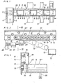
- Fig. 1 die Draufsicht auf eine Förderbahn mit Ausschleusvorrichtung;
- Fig. 2 einen Teilschnitt von der Seite;
- Fig. 3 die Schnittansicht gem. Linie III - III in Fig. 2;
- Fig. 4 einen Teilschnitt von der Seite einer anderen Ausführungsform;
- Fig, 5 die Teildraufsicht auf die Förderbahn gem. Fig. 4.
- Die Förderanlage gem. Fig. 1 weist einen Zuförderer 1 auf, an den rechtwinklig eine weitere Förderbahn 2 angeschlossen ist. Zum Umsetzen von Stückgut auf die Förderbahn 2 dient ein Umsetzer 3, der durch ein Steuergerät gesteuert wird, um nicht nur bestimmte Stückgüter auf die Förderbahn 2 zu setzen, sondern auch diese in eine bestimmte Stelle in Querrichtung der Förderbahn 2 zu fördern, wie mit den Stückgütern 5 und 6 angedeutet ist. Der Zuförderer 1 und die Förderbahn 2 weisen zum Tragen und Transportieren ein beliebiges Fördermittel 7 auf, beispielsweise ein Band oder Tragrollen. Der Antrieb erfolgt in herkömmlicher Weise. Das Fördermittel 7 der Förderbahn 2 ist in mehrere Abschnitte 7! , 7'', 7"', 7''' usw. aufgeteilt, zwischen denen je eine um eine waagerechte Achse 8 schwenkbare Ausschleusklappe 9 vorgesehen ist. Diese ist gleichfalls mit einem Transportmittel 10 ausgestattet und kann aus ihrer Transportlage in der Ebene des Transportmittels 7 in eine abgewinkelte schräge Ausschleuslage geschwenkt werden, wie in Fig. 2 angedeutet ist. In der Ausschleuslage liegt das freie Ende der Auschleusklappe 9 vor einer weiteren Transportbahn 11 oder einem zu füllenden Behälter 12, der seinerseits auf einer Förderbahn 13 steht und nach dem Füllen weitergerückt wird.
- Nach den Fig. 2 und 3 besteht das Transportmittel 7 aus zwischen seitlichen Längsprofilen 14 drehbar gelagerten Tragrollen 15, die durch einen oben aufliegenden Keilriemen 16 angetrieben werden. Zum Führen und Andrücken des Keilriemens 16 dienen Röllchen 17, die am Längsprofil 14 gelagert sind. Der Keilriemen 16 wird durch einen nicht dargestellten Motor im Gegenuhrzeigersinn in Umlauf versetzt, so daß das Stückgut auf den im Uhrzeigersinn drehenden Tragrollen 15 von links nach rechts gefördert wird. Die Tragrollen 15' der Ausschleusklappe 9 entsprechen den Tragrollen 15 der Förderbahn 2 und sind an einem Rahmen 18 gelagert, der auf der als Achse 8 dienenden Steckachse 19 der in Transportrichtung ersten Tragrolle 15" der Ausschleusklappe 9 schwenkbar angeordnet ist, so daß sie aus der Transportlage in der Ebene der Tragrollen 15 in die nach unten abgewinkelte Ausschleuslage geklappt werden kann, wie strichpunktiert angedeutet ist. Der Rahmen 18 besitzt unten einen nach unten ragenden Arm 20, an dem ein Stellmittel 21, z.B. die Kolbenstange eines Pneumatikzylinders, angelenkt ist. Das Stellmittel 21 ist an einer Querstrebe 22 zwischen das Längsprofil 14 tragenden Stützen 23 befestigt. Die Transport- und Ausschleuslage wird durch die beiden Endstellungen des Stellmittels 21 bestimmt.
- Die Tragrollen 151 der Ausschleusklappe 9 werden in der Transportstellung durch den Keilriemen 16 angetrieben. Sie können freilaufend ausgebildet sein, so daß sie also in der Ausschleuslage infolge ihrer Massenträgheit und durch das nach unten sich bewegende Stückgut in Drehung gehalten werden. Zweckmäßigerweise sind die Tragrollen 15' jedoch ständig angetrieben. Zu diesem Zweck ist die letzte Tragrolle 15 vor der Ausschleusklappe 9 mit deren ersten Tragrolle 15'' durch einen Riemen 24 o. dgl. verbunden. Die Tragrolle 15'' und die übrigen Tragrollen 15' der Ausschleusklappe 9 sind entsprechend paarweise durch Riemen 25 o. dgl. miteinander gekoppelt, so daß sie auch im abgesenkten Zustand weiterdrehen. Es ist ersichtlich, daß ein auf die Förderbahn 2 gesetztes Stückgut auf dessen Transportmittel 7 befördert wird, wobei es durch die Augen von an der Seite angebrachten Steuergeräten 26 abgetastet wird. Bei zutreffender Kennung wird die zugeordnete Ausschleusklappe 9 abgesenkt, so daß das Stückgut nach unten auf eine der angeschlossenen Förderbahnen 11 oder in den Behälter 12, wie auch in Fig: 2 angedeutet ist, gefördert wird. Die Schwenkbewegung, also das Absenken, das Verharren bis das Stückgut die Ausschleusklappe 9 verlassen hat und das Rückstellen kann durch ein Zeitrelais gesteuert werden, es kann aber auch eine Lichtschranke angeordnet sein, die nach Freigabe der Ausschleusklappe 9 das Signal zum Rückstellen gibt.
- Das Transportmittel 7 kann auch als Bandförderer ausgebildet sein, wie in den Fig. 4 und 5 gezeigt ist. Die Tragrollen 15 sind dann von einem Band 27 umspannt. Entsprechend können auch die Tragrollen 15' und 15" der Ausschleusklappe 9 von einem Band 28 umhüllt sein. Die Antriebsübertragung erfolgt wieder durch einen Riemen 24 zwischen den Tragrollen 15 und 15". Zusätzlich sind noch die Tragrollen 15 am Ende und Anfang der Fördermittel 7 beiderseits der Ausschleusklappe 9 durch einen weiteren Riemen 29 oder dgl. antriebsmäßig miteinander verbunden. Zum Absenken und Anheben der Ausschleusklappe 9 ist ebenfalls ein Stellmittel 21 vorgesehen. Die Funktion dieser Ausschleusvorrichtung entspricht der oben beschriebenen.
- Selbstverständlich kann das Ausschleusen auch nach oben erfolgen, wie in Fig. 4 angedeutet ist. Oberhalb der Förderbahn 2 ist dann eine Anschlußbahn 11' vorgesehen. Das Ausschleusen kann nur nach oben bzw. unten erfolgen oder, wie gezeigt, wahlweise nach oben oder unten. Dann ist der Hub des Stellmittels 21 so ausgelegt, daß die obere und die untere Ausschleuslage das jeweilige Hubende darstellt. Zum Festlegen der mittleren Transportlage in der Ebene der Förderbahn 2 ist ein Anschlag 30 vorgesehen, an dem in der Transportlage der verlängerte Arm 20' des Rahmens 18 anliegt und der sich mit seiner anderen Seite an einem stationären Gleitstück 31 abstützt. Zum Verstellen des Anschlages 30 nach unten dient ein Stellzylinder 32, der am Rahmen der Förderbahn 2 gelagert ist. Soll die Ausschleusklappe 9 nach unten ausschwenken, dann wird der Anschlag 30 nach unten verstellt, so daß der Arm 20' im Uhrzeigersinn schwenken kann. Der Anschlag 30 kann sich dann unverzüglich an die gerundete Unterseite 20" des Armes 20' anlegen, so daß er sofort bei Einnahme der Transportlage wieder in die Sperrstellung gelangt, wonach des Stellmittel 21 drucklos geschaltet wird.
- Denkbar ist es natürlich auch, die Förderbahn als Schwerkraftbahn bzw. Staurollenbahn auszubilden. Die Funktion der Ausschleusvorrichtung ist dann die gleiche. Natürlich können auch verschiedene Transportmittel in der Förderbahn 2 und der Ausschleusklappe 9 vorgesehen sein. Schließlich kann es zweckmäßig sein, daß die Antriebsvorrichtung 16,17 für das Transportmittel 7 ober- oder unterhalb des Transportmittels 7 angeordnet ist. Zur Unterbringung dieser Antriebsvorrichtung 16, 17 dient vorzugsweise das eine Längsprofil 14, das mit seiner offenen Seite gegen das Transportmittel 7 zeigt und dort eine durchgehend geschlossene Abdeckung 14' aufweist. Letztere dient sowohl zum Schutz der Antriebsvorrichtung 16, 17 als auch zur seitlichen Führung des Stückgutes auf dem Transportmittel 7.
- Es ist ersichtlich, daß unabhängig von der Ausbildung des Transportmittels 7 das Stückgut ohne seitliche Richtungsänderung, also in Transportrichtung aus der Förderbahn 2 ausgeschleust wird, wobei das Stückgut nicht relativ zum Transportmittel 7 bewegt wird. Der hohe stationäre Reibungsschluß bleibt so unverändert erhalten, so daß das Stückgut seinen Standort in Querrichtung auf dem Transportmittel 7 sicher beibehält. Es kann somit bereits bei der Aufgabe des Stückgutes auf das Transportmittel 7 eine quergefächerte Sortierung für die erforderliche Auftragszusammenstellung vorgenommen werden. Die Stückgutfolge kann ferner so dicht abgestimmt sein, daß während des Ausschleusens eines Stückgutes 5', also bei schräg gestellter Ausschleusklappe 9, das folgende Stückgut 6' bereits auf die Ausschleusklappe 9 aufläuft. Bevor dieses Stückgut 6' jedoch das Ende der Ausschleusklappe 9 erreicht hat, ist dieser wieder in ihrer Transportstellung, und das Stückgut 6' wird in Transportrichtung auf der Förderbahn 2 weiterbefördert (Fig. 1).
Claims (7)
Priority Applications (1)
| Application Number | Priority Date | Filing Date | Title |
|---|---|---|---|
| AT82101919T ATE13860T1 (de) | 1981-03-11 | 1982-03-10 | Ausschleusvorrichtung fuer eine foerderbahn. |
Applications Claiming Priority (2)
| Application Number | Priority Date | Filing Date | Title |
|---|---|---|---|
| DE3109174 | 1981-03-11 | ||
| DE19813109174 DE3109174A1 (de) | 1981-03-11 | 1981-03-11 | Ausschleusvorrichtung fuer eine foerderbahn |
Publications (3)
| Publication Number | Publication Date |
|---|---|
| EP0059984A2 true EP0059984A2 (de) | 1982-09-15 |
| EP0059984A3 EP0059984A3 (en) | 1982-12-15 |
| EP0059984B1 EP0059984B1 (de) | 1985-06-19 |
Family
ID=6126877
Family Applications (1)
| Application Number | Title | Priority Date | Filing Date |
|---|---|---|---|
| EP82101919A Expired EP0059984B1 (de) | 1981-03-11 | 1982-03-10 | Ausschleusvorrichtung für eine Förderbahn |
Country Status (3)
| Country | Link |
|---|---|
| EP (1) | EP0059984B1 (de) |
| AT (1) | ATE13860T1 (de) |
| DE (2) | DE3109174A1 (de) |
Cited By (18)
| Publication number | Priority date | Publication date | Assignee | Title |
|---|---|---|---|---|
| EP0106332A1 (de) * | 1982-10-18 | 1984-04-25 | Gebhardt Fördertechnik GmbH | Stauförderer für Stückgut mit Ausschleusstation |
| FR2593416A1 (fr) * | 1985-11-29 | 1987-07-31 | Meccanizzazione Postale Automa | Dispositif permettant de trier des colis |
| FR2678529A1 (fr) * | 1991-07-01 | 1993-01-08 | Bernard Dominique | Installation de tri automatique. |
| EP0627372A1 (de) * | 1993-05-05 | 1994-12-07 | Ltg Lufttechnische Gmbh | Stapelvorrichtung für tafelförmige Güter |
| FR2728249A1 (fr) * | 1994-12-20 | 1996-06-21 | Honda Motor Co Ltd | Procede et appareil de transport automatique de pieces |
| GR950100217A (el) * | 1995-06-06 | 1997-02-28 | Min Tech Engineers Ltd | Συστημα διακινησης κιβωτιων σε χωρους παραγωγης-συσκευασιας. |
| WO1997033795A1 (de) * | 1996-03-14 | 1997-09-18 | Robert Bosch Gmbh | Vorrichtung zum einbringen von gegenständen, insbesondere von gefüllten flachbeuteln in kartons |
| EP1556295B1 (de) * | 2002-10-28 | 2008-12-10 | Dematic Corp. | Förderer mit einem verbindungsstück zum verstellen der relativen winkellage von zwei aufeinanderfolgenden förderstrecken |
| WO2009071061A1 (de) * | 2007-12-06 | 2009-06-11 | Grenzebach Maschinenbau Gmbh | Vorrichtung und verfahren zum ausleiten von glasplatten in einer fertigungslinie |
| CN109051693A (zh) * | 2018-07-04 | 2018-12-21 | 福建省信捷机械有限公司 | 瓷砖检测装置的砖道调整机构 |
| CN110686253A (zh) * | 2019-10-10 | 2020-01-14 | 中城绿建科技有限公司 | 裂解气化炉进料装置及其进料方法 |
| CN111530782A (zh) * | 2019-05-03 | 2020-08-14 | 伟博泰有限公司 | 剔除装置 |
| CN111792283A (zh) * | 2020-07-28 | 2020-10-20 | Oppo(重庆)智能科技有限公司 | 筛选设备 |
| EP3730226A1 (de) * | 2019-04-23 | 2020-10-28 | Robowaste AB | Abfallsortiereinheit, system und verfahren zum sortieren von abfall |
| CN113245226A (zh) * | 2021-05-06 | 2021-08-13 | 安徽科达自动化集团股份有限公司 | 一种机械化包装纸盒检测机构 |
| CN113371395A (zh) * | 2021-06-01 | 2021-09-10 | 珠海格力智能装备有限公司 | 注塑皮带线的输送系统 |
| CN116198901A (zh) * | 2023-02-27 | 2023-06-02 | 佛山士力科技有限公司 | 一种铝型材分捡装置 |
| CN118988789A (zh) * | 2024-10-23 | 2024-11-22 | 连云港泓昊复合材料有限公司 | 一种玻璃纤维纸的检测设备 |
Families Citing this family (1)
| Publication number | Priority date | Publication date | Assignee | Title |
|---|---|---|---|---|
| DE3924374A1 (de) * | 1989-07-22 | 1991-01-31 | Nordischer Maschinenbau | Einrichtung zum teilen von filets |
Family Cites Families (7)
| Publication number | Priority date | Publication date | Assignee | Title |
|---|---|---|---|---|
| US1809456A (en) * | 1928-03-21 | 1931-06-09 | Streeter Edwin Henry | Transfer device |
| GB818892A (en) * | 1954-11-18 | 1959-08-26 | Baker Perkins Ltd | Improvements in and relating to bread loaf conveying means |
| BE678711A (de) * | 1965-04-07 | 1966-09-01 | ||
| US4011935A (en) * | 1975-09-08 | 1977-03-15 | Massey John P | Sorting machines |
| US4003462A (en) * | 1976-02-06 | 1977-01-18 | Perrott L F | Log sorting system |
| IT1082516B (it) * | 1977-01-25 | 1985-05-21 | Bruno & Co Alisyncro | Impianto per la distribuzione di prodotti alimentari particolarmente dolciari ad un a pluralita di stazioni di confezionamento poste in serie |
| DE8017695U1 (de) * | 1980-06-28 | 1980-10-16 | H. Wohlenberg Kg-Gmbh & Co, 3000 Hannover | Transportbandweiche |
-
1981
- 1981-03-11 DE DE19813109174 patent/DE3109174A1/de not_active Ceased
-
1982
- 1982-03-10 DE DE8282101919T patent/DE3264199D1/de not_active Expired
- 1982-03-10 EP EP82101919A patent/EP0059984B1/de not_active Expired
- 1982-03-10 AT AT82101919T patent/ATE13860T1/de not_active IP Right Cessation
Cited By (25)
| Publication number | Priority date | Publication date | Assignee | Title |
|---|---|---|---|---|
| EP0106332A1 (de) * | 1982-10-18 | 1984-04-25 | Gebhardt Fördertechnik GmbH | Stauförderer für Stückgut mit Ausschleusstation |
| FR2593416A1 (fr) * | 1985-11-29 | 1987-07-31 | Meccanizzazione Postale Automa | Dispositif permettant de trier des colis |
| FR2678529A1 (fr) * | 1991-07-01 | 1993-01-08 | Bernard Dominique | Installation de tri automatique. |
| WO1993001007A1 (fr) * | 1991-07-01 | 1993-01-21 | Avicole Communication Bretagne Service | Installation de tri automatique |
| EP0627372A1 (de) * | 1993-05-05 | 1994-12-07 | Ltg Lufttechnische Gmbh | Stapelvorrichtung für tafelförmige Güter |
| FR2728249A1 (fr) * | 1994-12-20 | 1996-06-21 | Honda Motor Co Ltd | Procede et appareil de transport automatique de pieces |
| GR950100217A (el) * | 1995-06-06 | 1997-02-28 | Min Tech Engineers Ltd | Συστημα διακινησης κιβωτιων σε χωρους παραγωγης-συσκευασιας. |
| WO1997033795A1 (de) * | 1996-03-14 | 1997-09-18 | Robert Bosch Gmbh | Vorrichtung zum einbringen von gegenständen, insbesondere von gefüllten flachbeuteln in kartons |
| AU707699B2 (en) * | 1996-03-14 | 1999-07-15 | Robert Bosch Gmbh | Device for the introduction of items, in particular of flat bags, into cartons |
| EP1556295B1 (de) * | 2002-10-28 | 2008-12-10 | Dematic Corp. | Förderer mit einem verbindungsstück zum verstellen der relativen winkellage von zwei aufeinanderfolgenden förderstrecken |
| WO2009071061A1 (de) * | 2007-12-06 | 2009-06-11 | Grenzebach Maschinenbau Gmbh | Vorrichtung und verfahren zum ausleiten von glasplatten in einer fertigungslinie |
| CN109051693A (zh) * | 2018-07-04 | 2018-12-21 | 福建省信捷机械有限公司 | 瓷砖检测装置的砖道调整机构 |
| EP3730226A1 (de) * | 2019-04-23 | 2020-10-28 | Robowaste AB | Abfallsortiereinheit, system und verfahren zum sortieren von abfall |
| WO2020216778A1 (en) * | 2019-04-23 | 2020-10-29 | Robowaste Ab | Waste sorting unit, system, method and use for sorting waste |
| US10947059B2 (en) | 2019-05-03 | 2021-03-16 | Wipotec Gmbh | Rejector device |
| CN111530782A (zh) * | 2019-05-03 | 2020-08-14 | 伟博泰有限公司 | 剔除装置 |
| EP3733314A1 (de) * | 2019-05-03 | 2020-11-04 | WIPOTEC GmbH | Ausschleusevorrichtung |
| CN110686253A (zh) * | 2019-10-10 | 2020-01-14 | 中城绿建科技有限公司 | 裂解气化炉进料装置及其进料方法 |
| CN110686253B (zh) * | 2019-10-10 | 2023-11-28 | 中城绿建科技有限公司 | 裂解气化炉进料装置及其进料方法 |
| CN111792283A (zh) * | 2020-07-28 | 2020-10-20 | Oppo(重庆)智能科技有限公司 | 筛选设备 |
| CN113245226A (zh) * | 2021-05-06 | 2021-08-13 | 安徽科达自动化集团股份有限公司 | 一种机械化包装纸盒检测机构 |
| CN113245226B (zh) * | 2021-05-06 | 2024-05-14 | 安徽科达自动化集团股份有限公司 | 一种机械化包装纸盒检测机构 |
| CN113371395A (zh) * | 2021-06-01 | 2021-09-10 | 珠海格力智能装备有限公司 | 注塑皮带线的输送系统 |
| CN116198901A (zh) * | 2023-02-27 | 2023-06-02 | 佛山士力科技有限公司 | 一种铝型材分捡装置 |
| CN118988789A (zh) * | 2024-10-23 | 2024-11-22 | 连云港泓昊复合材料有限公司 | 一种玻璃纤维纸的检测设备 |
Also Published As
| Publication number | Publication date |
|---|---|
| ATE13860T1 (de) | 1985-07-15 |
| DE3109174A1 (de) | 1982-10-14 |
| EP0059984A3 (en) | 1982-12-15 |
| EP0059984B1 (de) | 1985-06-19 |
| DE3264199D1 (en) | 1985-07-25 |
Similar Documents
| Publication | Publication Date | Title |
|---|---|---|
| EP0059984A2 (de) | Ausschleusvorrichtung für eine Förderbahn | |
| DE3215744C2 (de) | Verteilförderanlage für Stückgut | |
| DE3013315A1 (de) | Einrichtung zum foerdern und sortieren von gegenstaenden | |
| CH635044A5 (de) | Staufoerderer fuer stueckgut. | |
| DE3504365A1 (de) | Verteilervorrichtung fuer stueckgut | |
| DE2432579A1 (de) | Vorrichtung zum stapeln von buechern oder dgl. | |
| CH670809A5 (de) | ||
| DE1951598B2 (de) | Ausweichspur für eine Arbeitsvorrichtung enthaltende Fertigungsstraßen | |
| CH402731A (de) | Fördereinrichtung | |
| DE2446364A1 (de) | Vorrichtung zum transport von bogen, insbesondere an wellpappmaschinen | |
| DE3238511C1 (de) | Staufoerderer fuer Stueckgut mit Ausschleusstation | |
| DE2644136A1 (de) | Foerderbandsystem | |
| DE1293053B (de) | Schiffseigene Foerderanlage | |
| DE3615064A1 (de) | Foerdereinrichtung zum transport von werkstuecken | |
| DE2144637B2 (de) | Schiffseigene Förderanlage | |
| EP0060828A2 (de) | Gewächshaus | |
| AT409116B (de) | Anlage für den transport von schüttgut | |
| DE2731579A1 (de) | Stapelvorrichtung fuer profilstaebe aus stahl | |
| DE3601295A1 (de) | Bogenstapelvorrichtung fuer einstellbare formatbreiten | |
| DE2900139B2 (de) | Walzenförderer | |
| DE1261060B (de) | Vorrichtung zur Einzelueberfuehrung von Paketen | |
| DE2319339A1 (de) | Endlosfoerderer | |
| DE7335166U (de) | Förderer zur Aufnahme und zum Abtransport von Stapeln gefalteter Werkstücke, insbesondere Wäschestücke | |
| DE2249231C3 (de) | Gerät zum selbsttätigen Stapeln von plattenförmigen Werkstücken | |
| AT224527B (de) |
Legal Events
| Date | Code | Title | Description |
|---|---|---|---|
| PUAI | Public reference made under article 153(3) epc to a published international application that has entered the european phase |
Free format text: ORIGINAL CODE: 0009012 |
|
| AK | Designated contracting states |
Designated state(s): AT BE CH DE FR GB IT LI NL SE |
|
| PUAL | Search report despatched |
Free format text: ORIGINAL CODE: 0009013 |
|
| AK | Designated contracting states |
Designated state(s): AT BE CH DE FR GB IT LI NL SE |
|
| RHK1 | Main classification (correction) |
Ipc: B65G 47/64 |
|
| 17P | Request for examination filed |
Effective date: 19830309 |
|
| ITF | It: translation for a ep patent filed | ||
| GRAA | (expected) grant |
Free format text: ORIGINAL CODE: 0009210 |
|
| AK | Designated contracting states |
Designated state(s): AT BE CH DE FR GB IT LI NL SE |
|
| REF | Corresponds to: |
Ref document number: 13860 Country of ref document: AT Date of ref document: 19850715 Kind code of ref document: T |
|
| REF | Corresponds to: |
Ref document number: 3264199 Country of ref document: DE Date of ref document: 19850725 |
|
| ET | Fr: translation filed | ||
| PGFP | Annual fee paid to national office [announced via postgrant information from national office to epo] |
Ref country code: AT Payment date: 19860115 Year of fee payment: 5 |
|
| PLBI | Opposition filed |
Free format text: ORIGINAL CODE: 0009260 |
|
| 26 | Opposition filed |
Opponent name: SEITZ ENZINGER NOLL MASCHINENBAU AG Effective date: 19860125 |
|
| NLR1 | Nl: opposition has been filed with the epo |
Opponent name: SEITZ ENZINGER NOLL MASCHINENBAU AG |
|
| PGFP | Annual fee paid to national office [announced via postgrant information from national office to epo] |
Ref country code: NL Payment date: 19870331 Year of fee payment: 6 |
|
| BERE | Be: lapsed |
Owner name: GEBHARDT FORDERTECHNIK G.M.B.H. Effective date: 19870330 |
|
| BERR | Be: reestablished |
Owner name: *GEBHARDT FORDERTECHNIK G.M.B.H. Effective date: 19871208 |
|
| RDAG | Patent revoked |
Free format text: ORIGINAL CODE: 0009271 |
|
| STAA | Information on the status of an ep patent application or granted ep patent |
Free format text: STATUS: PATENT REVOKED |
|
| GBPR | Gb: patent revoked under art. 102 of the ep convention designating the uk as contracting state | ||
| 27W | Patent revoked |
Effective date: 19880715 |
|
| REG | Reference to a national code |
Ref country code: CH Ref legal event code: PL |
|
| NLR2 | Nl: decision of opposition | ||
| BERE | Be: lapsed |
Owner name: GEBHARDT FORDERTECHNIK G.M.B.H. Effective date: 19890331 |
|
| EUG | Se: european patent has lapsed |
Ref document number: 82101919.7 |