EP0059818A1 - Machine for placing individual protection strips around oblong objects such as bottles, and an assembly of such machines - Google Patents
Machine for placing individual protection strips around oblong objects such as bottles, and an assembly of such machines Download PDFInfo
- Publication number
- EP0059818A1 EP0059818A1 EP19810401472 EP81401472A EP0059818A1 EP 0059818 A1 EP0059818 A1 EP 0059818A1 EP 19810401472 EP19810401472 EP 19810401472 EP 81401472 A EP81401472 A EP 81401472A EP 0059818 A1 EP0059818 A1 EP 0059818A1
- Authority
- EP
- European Patent Office
- Prior art keywords
- strip
- jaws
- machine according
- objects
- article
- Prior art date
- Legal status (The legal status is an assumption and is not a legal conclusion. Google has not performed a legal analysis and makes no representation as to the accuracy of the status listed.)
- Granted
Links
Images


Classifications
-
- B—PERFORMING OPERATIONS; TRANSPORTING
- B65—CONVEYING; PACKING; STORING; HANDLING THIN OR FILAMENTARY MATERIAL
- B65B—MACHINES, APPARATUS OR DEVICES FOR, OR METHODS OF, PACKAGING ARTICLES OR MATERIALS; UNPACKING
- B65B55/00—Preserving, protecting or purifying packages or package contents in association with packaging
- B65B55/20—Embedding contents in shock-absorbing media, e.g. plastic foam, granular material
-
- B—PERFORMING OPERATIONS; TRANSPORTING
- B65—CONVEYING; PACKING; STORING; HANDLING THIN OR FILAMENTARY MATERIAL
- B65B—MACHINES, APPARATUS OR DEVICES FOR, OR METHODS OF, PACKAGING ARTICLES OR MATERIALS; UNPACKING
- B65B21/00—Packaging or unpacking of bottles
- B65B21/24—Enclosing bottles in wrappers
Definitions
- the present invention firstly relates to a machine for the automatic installation of individual protective strips on elongated objects such as bottles.
- These bands can be made of corrugated cardboard or any other material capable of protecting the objects in question from impact, in the manner of well-known straws used to protect the bottles. These bands will however be able to effectively fulfill this protective role while only extending along part of the height of said objects and thus, in the case of bottles of conventional shape, with round or square belly, they may not extend only about halfway up the bottle, starting from the base. These strips will therefore in principle consist of cardboard or similar cutouts, of essentially rectangular shape.
- these protective bands can advantageously replace, in the packaging boxes, the braces usually used to separate the bottles or other objects of the same kind, and prevent them from colliding.
- the use of bands has the advantage over the crossbars that they also protect the labels of the bottles, preventing them from being damaged or their inscriptions being erased.
- the object of the present invention is to solve this particular problem and, for this purpose, a machine for the automatic laying of individual protective strips on elongated objects such as bottles is, according to the invention, characterized in that it essentially comprises: means for bringing said objects one behind the other, in a standing position, in a continuous line; means for bringing successive bands to the practical position vertical; means for stopping the object at the head of the queue in front of a guided strip stopped in a vertical position; means for shaping the strip around said object; means for fixing the ends of the shaped strip; and means for removing the object coated with said strip.
- shaping means may be produced in different ways, but it may be particularly advantageous, in accordance with one embodiment, to provide that said shaping means comprise inter alia, in a loading station, at least one pair of jaws whose internal surfaces are in the form of cylindrical portions of vertical axes, these jaws being articulated so as to be able on the one hand to open, leaving a lateral passage to an object and to its strip during conformation, and d 'on the other hand close on this object coated with said strip.
- said shaping means may further comprise, at said loading station, a pusher with an internal surface in the form of a cylindrical portion with a vertical axis, open laterally in the direction of said pair of jaws, and capable of moving in this direction, by pushing said object at the head of the file, between a withdrawal position for which it leaves a passage for said object, and an advanced position for which the latter, coated with said strip, is introduced between said jaws, after which said pusher can return empty to said withdrawal position.
- a pusher with an internal surface in the form of a cylindrical portion with a vertical axis, open laterally in the direction of said pair of jaws, and capable of moving in this direction, by pushing said object at the head of the file, between a withdrawal position for which it leaves a passage for said object, and an advanced position for which the latter, coated with said strip, is introduced between said jaws, after which said pusher can return empty to said withdrawal position.
- the object therefore behaves, vis-à-vis the strip to be shaped, like a punch, cooperating with the matrix that constitute said jaws.
- Said loading station may also be provided with two fixed conformers in the form of vertical plates extending in a general direction parallel to that in which the objects to be coated are brought to said station, and also extending to the outside of the jaws, from those of the edges thereof which delimit said lateral passage when they are in the open position.
- the two edges facing each other, of these conformers can advantageously be rounded, to facilitate the introduction and the guiding of the strip between the jaws, without it risking being cut in contact with the edges of the jaws which delimit the lateral passage. of these.
- said pair of jaws is part of a group of at least three pairs of similar jaws, mounted on a common turntable, around the vertical axis of rotation. of it, this plate being associated with drive means suitable for rotating it step by step.
- the fixing means mentioned above can therefore be provided in a fixing station located opposite the location occupied by a pair of jaws when the pair which precedes it (having regard to the direction of rotation of said turntable) is stopped at said loading station, while the third pair of jaws is stopped at a station called evacuation station.
- the machine thus essentially comprises three stations, operating in synchronism: a loading station, a fixing station, and an evacuation station.
- a machine according to the invention may also have more specific characteristics, which are of interest to one or other of these positions.
- said means for feeding successive bands in a practically vertical position, to include gripping means - of the suction cup type or the like - for a band in a store carrying a battery. strips, and guide means - of the kind with fixed pushers, rollers and / or slides - suitable for guiding the strip taken to a vertical position facing the object at the head of the queue, this object being stopped .
- fixing means may include means of supply at least one end of adhesive tape overlapping the two ends of the strip formed around the object, means for applying this end to the strip, and means for cutting the strip, to leave, glued to the headband, the desired length.
- said supply means are capable of gluing the end or ends of adhesive tape in a direction perpendicular to the junction line of said ends of the strip.
- the evacuation means located at the outlet of the machine, they may comprise on the one hand means for reopening the jaws, and on the other hand an ejection lever or the like, capable of extracting between the jaws open an object covered with its blindfold.
- This object can of course be ejected directly onto a conveyor belt or the like, to be taken, for example, to a machine for packaging objects in the crate.
- the various means envisaged for ensuring the various functions of a machine according to the invention it will be particularly advantageous, again, to ensure that the means for bringing objects one behind the other and the means for evacuating objects coated with their strip are arranged so as to move the objects in parallel directions, in the same direction and at the same level.
- the present invention also relates to a set of such machines.
- such a set of machines can be essentially characterized in that it comprises several machines operating in synchronism and whose respective means of supplying and evacuating said objects provide them with displacements in directions which are all parallel, in the same direction and at same level, and in that said machines are regularly offset laterally and from upstream to downstream, one relative to the next, said machines being thus aligned in an oblique direction relative to said parallel directions.
- the machine comprises as an essential and central element a turntable 4 capable of being driven in rotation step by step about its central axis, which is vertical. On this plate are arranged three pairs of jaws or clamps 5, mounted on pivoting arms 6 of the plate 4.
- the cutout or strip 7 is thus brought into a vertical position, and at a standstill on the machine table, at the level of the turntable 4, in a position such that it is located between the bottle 8 at a standstill on the stop 11 and a lateral passage delimited by the edges or edges 18 of the corresponding jaws 5, then themselves stopped at said loading station 1, and in the open position.
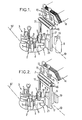
- the bottle 8 it is then located between the strip 7 and a movable pusher 19 perpendicular to the direction 10, in a back-and-forth movement, between a withdrawal position ( Figures 1 and 2) for which it leaves passage to the bottle, and an advanced position corresponding to the introduction of the bottle between the jaws.
- these shapers consist of vertical plates, and extend parallel to the direction 10, outward from the edges 18 when the jaws are in the open position; these conformers have, as can be seen in the various figures, their edges which face rounded 22, which allows appropriate guiding of the strip without the risk that it will be damaged, in particular by contact with the edges 18 of the jaws.
- the front face of the aforementioned pusher 19 may at the same time constitute a stop for the next bottle 8 while the previous bottle is introduced between the jaws 5.
- suitable fixing means will make it possible to join the two ends of the rolled-up strip 7. It will be convenient for this purpose to provide at least a portion of adhesive tape stuck astride the junction line of these two ends.
- junction line We can provide a piece of adhesive tape glued longitudinally along all or part of this junction line, but we can more conveniently provide one or two sections of adhesive tape glued, on the contrary, transversely on this junction line, for example at the top and downstairs.
- the machine comprises two coils 24 of adhesive strips 24a, these strips being led towards the aforementioned junction line by means of drive rollers 25, counter-thrust rollers 26 and return rollers 27 and 28.
- Pressure members 29 carried by a support 30 can press the desired length of adhesive tape on the strip 7, on either side of the aforementioned junction line, and then knives 31, also carried by the support 30, cut the sections of adhesive tape to the desired length.
- the turntable 4 is still driven in rotation over a third of a turn, and the two jaws considered 5 arrive at the evacuation station 3 and open to allow the evacuation of the bottle 8 equipped with its strip 7 on a outlet conveyor 32 ( Figure 6).
- the ejection of the bottle 8 from the open jaws 5 can be ensured by a rotary ejector 33.
- the evacuation conveyor 32 extends in a direction 10 ′ which is parallel to the direction 10 for supplying naked bottles to the machine.
- reference lines 9a, 9b, 9c and 9d refer to the supply conveyors of the four machines of the assembly, and in 32a, 32b, 32c and 32d their respective evacuation conveyors.
- each machine will be able to equip their headband with at least sixty bottles per minute, which corresponds to an equipment rate of 240 bottles per minute for a set of four machines.
Abstract
Description
La présente invention concerne tout d'abord une machine pour la pose automatique de bandeaux de protection individuels sur des objets allongés tels que des bouteilles.The present invention firstly relates to a machine for the automatic installation of individual protective strips on elongated objects such as bottles.
Ces bandeaux peuvent être en carton ondulé ou en tout autre matériau propre à protéger des chocs les objets en question, à la manière des paillons bien connus, utilisés pour protéger les bouteilles. Ces bandeaux'pourront toutefois remplir efficacement ce rôle de protection tout en ne s'étendant que selon une partie de la hauteur desdits objets et ainsi, dans le cas de bouteilles de forme classique, à ventre à section ronde où-carrée, ils pourront ne s'étendre environ que jusqu'à mi-hauteur de la bouteille, à partir du culot. Ces bandeaux seront donc en principe constitués de découpes de carton ou analogue, de forme essentiellement rectangulaire.These bands can be made of corrugated cardboard or any other material capable of protecting the objects in question from impact, in the manner of well-known straws used to protect the bottles. These bands will however be able to effectively fulfill this protective role while only extending along part of the height of said objects and thus, in the case of bottles of conventional shape, with round or square belly, they may not extend only about halfway up the bottle, starting from the base. These strips will therefore in principle consist of cardboard or similar cutouts, of essentially rectangular shape.
On conçoit que ces bandeaux de protection pourront remplacer avantageusement, dans les caisses d'emballage, les croisillons habituellement utilisés pour séparer les bouteilles ou autres objets du même genre, et éviter qu'ils ne s'entrechoquent. L'utilisation des bandeaux présente, sur les croisillons, l'avantage qu'ils protègent en outre les étiquettes des bouteilles, en évitant que celles-ci soient détériorées ou que leurs inscriptions soient effacées par érosion.It is understood that these protective bands can advantageously replace, in the packaging boxes, the braces usually used to separate the bottles or other objects of the same kind, and prevent them from colliding. The use of bands has the advantage over the crossbars that they also protect the labels of the bottles, preventing them from being damaged or their inscriptions being erased.
Cependant, le problème se présente d'assurer une pose rapide et automatique de tels bandeaux sur des bouteilles à emballer à cadence élevée.However, the problem arises of ensuring rapid and automatic installation of such strips on bottles to be packaged at a high rate.
Le but de la présente invention est de résoudre ce problème particulier et, à cet effet, une machine pour la pose automatique de bandeaux de protection individuels sur des objets allongés tels que des bouteilles est, conformément à l'invention, caractérisée en ce qu'elle comporte essentiellement : desmoyens d'amenée desdits objets l'un derrière l'autre, en position debout, selon une file continue ; des moyens d'amenée de bandeaux successifs en position pratiquement verticale ; des moyens d'arrêt de l'objet de tête de la file face à un bandeau guidé et arrêté en position verticale ; des moyens de conformation du bandeau autour dudit objet ; des moyens de fixation des extrémités du bandeau conformé ; et des moyens d'évacuation de l'objet revêtu dudit bandeau.The object of the present invention is to solve this particular problem and, for this purpose, a machine for the automatic laying of individual protective strips on elongated objects such as bottles is, according to the invention, characterized in that it essentially comprises: means for bringing said objects one behind the other, in a standing position, in a continuous line; means for bringing successive bands to the practical position vertical; means for stopping the object at the head of the queue in front of a guided strip stopped in a vertical position; means for shaping the strip around said object; means for fixing the ends of the shaped strip; and means for removing the object coated with said strip.
Bien entendu, tous les moyens précités seront commandés selon un cycle de fonctionnement et selon des séquences appropriées, propres à assurer à grande cadence les différentes fonctions voulues, ceci en faisant appel à tous les moyens (moteurs, de détection de position, de synchronisation, mécaniques, hydrauliques et électroniques) actuellement à la disposition du technicien dans ce domaine.Of course, all of the aforementioned means will be controlled according to an operating cycle and according to appropriate sequences, capable of ensuring the various desired functions at high speed, this using all the means (motors, position detection, synchronization, mechanical, hydraulic and electronic) currently available to the technician in this area.
Ces différents moyens, étant bien connus, ne seront pas décrits plus en détail.These various means, being well known, will not be described in more detail.
Les moyens de conformation cités plus haut pourront être réalisés de différentes façons, mais il pourra être particulièrement avantageux, conformément à un mode de réalisation, de prévoir que lesdits moyens de conformation comprennent entre autres, en un poste de chargement, au moins une paire de mâchoires dont les surfaces internes sont en forme de portions cylindriques d'axes verticaux, ces mâchoires étant articulées de sorte à pouvoir d'une part s'ouvrir en laissant un passage latéral à un objet et à son bandeau en cours de conformation, et d'autre part se refermer sur cet objet revêtu dudit bandeau.The above-mentioned shaping means may be produced in different ways, but it may be particularly advantageous, in accordance with one embodiment, to provide that said shaping means comprise inter alia, in a loading station, at least one pair of jaws whose internal surfaces are in the form of cylindrical portions of vertical axes, these jaws being articulated so as to be able on the one hand to open, leaving a lateral passage to an object and to its strip during conformation, and d 'on the other hand close on this object coated with said strip.
Le mode de fonctionnement de ces mâchoires sera mieux vu par la suite, mais on peut noter déjà qu'il s'agit là de moyens commodes et mécaniquement très simples et fiables, d'enrouler une bande de carton ou analogue, destinée à constituer le bandeau, autour de l'objet en question -bouteille ou autre- et de maintenir ce bandeau serré sur l'objet jusqu'à ce que les moyens de fixation précités interviennent. De plus, et comme cela sera également vu par la suite, ces mâchoires peuvent assurer très facilement un transfert de l'objet revêtu de son bandeau vers le poste suivant de la machine.The mode of operation of these jaws will be better seen later, but it can already be noted that these are convenient and mechanically very simple and reliable means of winding up a strip of cardboard or the like, intended to constitute the band, around the object in question - bottle or other - and keep this band tight on the object until the aforementioned fixing means intervene. In addition, and as will also be seen subsequently, these jaws can very easily ensure a transfer of the object coated with its strip to the next station of the machine.
En coopération et en complément de ces mâchoires, lesdits moyens de conformation pourront comprendre en outre, audit poste de chargement, un poussoir à surface interne en forme de portion cylindrique d'axe vertical, ouvert latéralement en direction de ladite paire de mâchoires, et propre à se déplacer dans cette direction, en poussant ledit objet de tête de la file, entre une position de retrait pour laquelle il laisse un passage audit objet, et une position avancée pour laquelle celui-ci, revêtu dudit bandeau, est introduit entre lesdites mâchoires, après quoi ledit poussoir peut revenir à vide vers ladite position de retrait.In cooperation and in addition to these jaws, said shaping means may further comprise, at said loading station, a pusher with an internal surface in the form of a cylindrical portion with a vertical axis, open laterally in the direction of said pair of jaws, and capable of moving in this direction, by pushing said object at the head of the file, between a withdrawal position for which it leaves a passage for said object, and an advanced position for which the latter, coated with said strip, is introduced between said jaws, after which said pusher can return empty to said withdrawal position.
On comprend que , en ce poste de chargement de la mâchoire, l'objet de tête de la file, alors à l'arrêt, se place entre le bandeau, également à l'arrêt, et ledit poussoir, le bandeau étant lui-même situé entre l'objet et le passage latéral des mâchoires, alors ouvertes. C'est donc le mouvement latéral du poussoir vers les mâchoires qui, par l'intermédiaire de l'objet, provoquera le pliage du bandeau autour de l'objet, en même temps que l'introduction de celui-ci entre les mâchoires, lesquelles pourront alors se refermer.It is understood that, in this jaw loading station, the object at the head of the queue, while stopped, is placed between the strip, also stopped, and said pusher, the strip itself located between the object and the lateral passage of the jaws, then open. It is therefore the lateral movement of the pusher towards the jaws which, through the object, will cause the strip to fold around the object, at the same time as the introduction of the latter between the jaws, which can then close.
L'objet se comporte donc, vis-à-vis du bandeau à conformer, comme un poinçon, coopérant avec la matrice que constituent lesdites mâchoires. Par un tel système, on obtient un ajustement très précis du bandeau autour des objets, ce qui limite les risques de glissement par rotation, et ceci même si le diamètre des objets (dans le cas de bouteilles à ventre rond) est susceptible de varier légèrement.The object therefore behaves, vis-à-vis the strip to be shaped, like a punch, cooperating with the matrix that constitute said jaws. By such a system, a very precise adjustment of the strip around the objects is obtained, which limits the risks of sliding by rotation, even if the diameter of the objects (in the case of bottles with round bellies) is likely to vary slightly. .
Audit poste de chargement peuvent encore être prévus deux conformateurs fixes se présentant sous la forme de plaques verticales s'étendant dans une direction générale parallèle à celle selon laquelle les objets à revêtir sont amenés audit poste, et s'étendant, également, à l'extérieur des mâchoires, à partir de celles des arêtes de celles-ci qui délimitent ledit passage latéral lorsqu'elles sont en position d'ouverture.Said loading station may also be provided with two fixed conformers in the form of vertical plates extending in a general direction parallel to that in which the objects to be coated are brought to said station, and also extending to the outside of the jaws, from those of the edges thereof which delimit said lateral passage when they are in the open position.
Les deux arêtes se faisant face, de ces conformateurs, pourront avantageusement être arrondies, pour faciliter l'introduction et le guidage du bandeau entre les mâchoires, sans qu'il risque d'être coupé au contact des arêtes des mâchoires qui délimitent le passage latéral de celles-ci.The two edges facing each other, of these conformers, can advantageously be rounded, to facilitate the introduction and the guiding of the strip between the jaws, without it risking being cut in contact with the edges of the jaws which delimit the lateral passage. of these.
. Selon une disposition également importante de l'invention, on pourra avantageusement prévoir que ladite paire de mâchoires fait partie d'un groupe d'au moins trois paires de mâchoires semblables, montées sur un plateau tournant commun, autour de l'axe de rotation vertical de celui-ci, ce plateau étant associé à des moyens d'entrainement propres à le faire tourner pas à pas.. According to an equally important arrangement of the invention, it is advantageously possible to provide that said pair of jaws is part of a group of at least three pairs of similar jaws, mounted on a common turntable, around the vertical axis of rotation. of it, this plate being associated with drive means suitable for rotating it step by step.
Il s'agit là d'une disposition très importante, car elle permet bien entendu une grande cadence de pose des bandeaux sur les objets, avec un minimum de retard dans le parcours que ceux-ci effectuent vers les caisses d'emballage.This is a very important provision, because it allows of course a great rate of installation of the banners on the objects, with a minimum delay in the journey that they make towards the packing boxes.
Quant aux moyens de fixation cités plus haut, ils pourront donc être prévus en un poste de fixation situé vis-à-vis de l'emplacement qu'occupe une paire de mâchoires lorsque la paire qui la précède (eu égard au sens de rotation dudit plateau tournant) est arrêtée audit poste de chargement, tandis que la troisième paire de mâchoires est arrêtée en un poste dit poste d'évacuation.As for the fixing means mentioned above, they can therefore be provided in a fixing station located opposite the location occupied by a pair of jaws when the pair which precedes it (having regard to the direction of rotation of said turntable) is stopped at said loading station, while the third pair of jaws is stopped at a station called evacuation station.
La machine comporte ainsi essentiellement trois postes, fonctionnant en synchronisme : un poste de chargement, un poste de fixation, et un poste d'évacuation.The machine thus essentially comprises three stations, operating in synchronism: a loading station, a fixing station, and an evacuation station.
Outre ces dispositions générales et importantes, une machine conforme à l'invention pourra encore présenter des caractéristiques plus particulières, intéressant tel ou tel de ces postes.In addition to these general and important provisions, a machine according to the invention may also have more specific characteristics, which are of interest to one or other of these positions.
Notamment, au poste de chargement, il pourra être prévu avantageusement que lesdits moyens d'amenée de bandeaux successifs, en position pratiquement verticale, comprennent des moyens de préhension -du genre à ventouses ou analogues- d'un bandeau dans un magasin portant une pile de bandeaux, et des moyens de guidage -du genre à poussoirs, rouleaux et/ ou glissières fixes- propres à guider le bandeau prélevé vers une position verticale faisant face à l'objet de tête de la file, cet objet étant à l'arrêt.In particular, at the loading station, provision could advantageously be made for said means for feeding successive bands, in a practically vertical position, to include gripping means - of the suction cup type or the like - for a band in a store carrying a battery. strips, and guide means - of the kind with fixed pushers, rollers and / or slides - suitable for guiding the strip taken to a vertical position facing the object at the head of the queue, this object being stopped .
Là encore, il s'agit de moyens simples mais particulièrement fiables.Again, these are simple but particularly reliable means.
Pour ce qui est des moyens de fixation prévus au poste dit de fixation,ils pourront comprendre des moyens d'amenée d'au moins une extrémité de bande adhésive à chevaucher les deux extrémités du bandeau conformé autour de l'objet, des moyens d'application de cette extrémité sur le bandeau, et des moyens de coupe de la bande, pour laisser, collée sur le bandeau, la longueur voulue.As regards the fixing means provided at the so-called fixing station, they may include means of supply at least one end of adhesive tape overlapping the two ends of the strip formed around the object, means for applying this end to the strip, and means for cutting the strip, to leave, glued to the headband, the desired length.
De préférence encore, mais non obligatoirement, lesdits moyens d'amenée sont aptes à coller la ou les extrémités de bande adhésive selon une direction perpendiculaire à la ligne de jonction desdites extrémités du bandeau.More preferably, but not necessarily, said supply means are capable of gluing the end or ends of adhesive tape in a direction perpendicular to the junction line of said ends of the strip.
Quant aux moyens d'évacuation, situés à la sortie de la machine, ils pourront comprendre d'une part des moyens de réouverture des mâchoires, et d'autre part un levier d'éjection ou analogue, apte à extraire d'entre les mâchoires ouvertes un objet revêtu de son bandeau. Cet objet pourra bien entendu être éjecté directement sur une bande convoyeuse ou analogue, pour être conduit, par exemple, vers une machine d'emballage des objets en caisse.As for the evacuation means, located at the outlet of the machine, they may comprise on the one hand means for reopening the jaws, and on the other hand an ejection lever or the like, capable of extracting between the jaws open an object covered with its blindfold. This object can of course be ejected directly onto a conveyor belt or the like, to be taken, for example, to a machine for packaging objects in the crate.
Quoi qu'il en soit par ailleurs des différents moyens envisagés pour assurer les diverses fonctions d'une machine conforme à l'invention, il sera particulièrement avantageux, encore, de faire en sorte que les moyens d'amenée des objets l'un derrière l'autre et les moyens d'évacuation des objets revêtus de leur bandeau solent agencés pour assurer un déplacement des objets selon des directions parallèles, de même sens et au même niveau.Anyway, moreover, the various means envisaged for ensuring the various functions of a machine according to the invention, it will be particularly advantageous, again, to ensure that the means for bringing objects one behind the other and the means for evacuating objects coated with their strip are arranged so as to move the objects in parallel directions, in the same direction and at the same level.
Le dessin montre bien en quoi cette disposition est particulièrement avantageuse.The drawing clearly shows how this arrangement is particularly advantageous.
Plusieurs machines réalisées ce la façon qui vient d'être décrite pourront être associées en vue d'assurer une plus grande production, en fonctionnant donc en parallèle.Several machines produced in the way just described can be combined in order to ensure greater production, therefore operating in parallel.
La présente invention porte encore sur un ensemble de telles machines.The present invention also relates to a set of such machines.
Conformément à un autre aspect de l'invention, un tel ensemble de machines pourra être essentiellement caractérisé en ce qu'il comprend plusieurs machines fonctionnant en synchronisme et dont les moyens respectifs d'amenée et d'évacuation desdits objets assurent à ceux-ci des deplacements selon des directions qui sont toutes parallèles, de même sens et au même niveau, et en ce que lesdites machines sont régulièrement décalées latéralement et de l'amont vers l'aval, l'une par rapport à la suivante, lesdites machines étant ainsi alignées selon une direction oblique par rapport auxdites directions parallèles.In accordance with another aspect of the invention, such a set of machines can be essentially characterized in that it comprises several machines operating in synchronism and whose respective means of supplying and evacuating said objects provide them with displacements in directions which are all parallel, in the same direction and at same level, and in that said machines are regularly offset laterally and from upstream to downstream, one relative to the next, said machines being thus aligned in an oblique direction relative to said parallel directions.
Là encore le dessin montrera, mieux que des explications, en quoi cette disposition est particulièrement intéressante, en ce que, notamment, elle permet d'obtenir un ensemble de machines particulièrement compact. Here again the drawing will show, better than explanations, why this arrangement is particularly interesting, in that, in particular, it makes it possible to obtain a particularly compact set of machines.
Un mode d'exécution de l'invention va maintenant être décrit à titre d'exemple nullement limitatif, avec référence aux figures du dessin annexé dans lequel :
- - les figures 1 à 6 représentent très schématiquement et partiellement une machine conforme à l'invention, dans ses séquences successives de fonctionnement ; et
- - la figure 7 montre un ensemble de telles machines, également conforme à l'invention.
- - Figures 1 to 6 show very schematically and partially a machine according to the invention, in its successive operating sequences; and
- - Figure 7 shows a set of such machines, also according to the invention.
Les mêmes références ont bien entendu été utilisées sur les différentes figures pour désigner les mêmes parties, éléments ou organes.The same references have of course been used in the different figures to designate the same parts, elements or members.
Sur les figures, on a référencé globalement en 1, 2 et 3, respectivement, le poste de chargement, le poste de fixation, et le poste d'évacuation d'une machine conforme à l'invention. Pour ne pas surcharger le dessin et aussi pour faciliter les explications, on n'a pas représenté systématiquement tous les organes de la machine sur toutes les figures.In the figures, reference is made generally in 1, 2 and 3, respectively, the loading station, the fixing station, and the evacuation station of a machine according to the invention. In order not to overload the drawing and also to facilitate the explanations, we have not systematically shown all the components of the machine in all the figures.
La machine comporte comme élément essentiel et central un-plateau tournant 4 propre à être entrainé en rotation pas à pas autour de son axe central, lequel est vertical. Sur ce plateau sont disposées trois paires de mâchoires ou pinces 5, montées sur des bras pivotants 6 du plateau 4.The machine comprises as an essential and central element a
Les autres éléments de la machine vont maintenant être énumérés et décrits en relation avec la description de leur fonctionnement. Les objets à revêtir de bandeaux 7, que l'on supposera dans ce qui suit être des bouteilles 8 à corps rond, sont amenés au poste 1 par un convoyeur 9 (figures 5 et 6), selon une direction d'amenée 10, en une file ininterrompue. Avant que la bouteille de tête de la file ne soit arrêtée par une butée ou analogue 11 du poste de chargement, un bandeau 7 est prélevé par des ventouses 12 (portées par des bras pivotants 13) dans un magasin 14 de bandeaux 7 ; ceux-ci sont constitués par de simples rectangles de carton empilés dans le magasin (figure 1). Le bandeau prélevé 7 est alors poussé vers le bas par des griffes 15 montées coulissantes sur les bras 13 (figures 2 à 4) et introduit d'une part entre deux rouleaux de transfert entraînés en sens inverses 16, et d'autre part entre deux glissières de guidage verticales 17 (figure 2). L'ensemble des organes 12, 13 et 15 à 17 constitue ce que l'on a appelé plus haut les "moyens d'amenée de bandeaux". La découpe ou bandeau 7 est ainsi amenée en position verticale, et à l'arrêt sur la table de la machine, au niveau du plateau tournant 4, dans une position telle qu'elle se situe entre la bouteille 8 à l'arrêt sur la butée 11 et un passage latéral délimité par les bords ou arêtes 18 des mâchoires 5 correspondantes, alors elles-mêmes à l'arrêt audit poste de chargement 1, et en position ouverte.The other elements of the machine will now be listed and described in relation to the description of their operation. The objects to be coated with
Quant à la bouteille 8, elle est alors située entre le bandeau 7 et un poussoir 19 mobile perpendiculairement à la direction 10, selon un mouvement de va-et-vient, entre une position de retrait (figures 1 et 2) pour laquelle il laisse passage à la bouteille, et une position avancée correspondant à l'introduction de la bouteille entre les mâchoires.As for the
Ceci étant, on voit (figure 3) que le déplacement latéral du poussoir 19 dans la direction de la flèche 20 produira-l'engagement de la bouteille 8 entre les mâchoires ouvertes 5, par le passage latéral ménagé entre les arêtes 18 de celles-ci avec, simultanément, l'engagement du bandeau 7 et son pliage entre les faces intérieures cylindriques des mâchoires 5 et la bouteille, celle-ci agissant ainsi comme un poinçon coopérant avec la matrice que constituent lesdites mâchoires 5. On obtient de la sorte un ajustement et un enroulement très précis du bandeau 7 autour du corps de la bouteille 8. Cet enroulement du bandeau 7 autour de la bouteille 8, tandis que celle-ci est introduite entre les mâchoires, est facilité par des guides de pliage fixes ou conformateurs 21. Comme cela a été dit plus haut, ces conformateurs sont constitués de plaques verticales, et s'étendent parallèlement à la direction 10,vers l'extérieur à partir des arêtes 18 lorsque les mâchoires sont en position ouverte ; ces conformateurs ont, comme on le voit sur les différentes figures, leurs bords qui se font face 22 arrondis, ce qui permet un guidage approprié du bandeau sans risque que celui-ci soit détérioré, notamment par un contact avec les arêtes 18 des mâchoires.This being the case, it can be seen (FIG. 3) that the lateral displacement of the
Les organes ci-dessus référencés 5, 19 et 21 constituent ainsi ce que l'on a appelé plus haut, d'une façon générale, les "moyens de conformation" des bandes.The above-referenced
Il est à noter ici que la face antérieure du poussoir précité 19 pourra constituer en même temps une butée d'arrêt pour la bouteille 8 suivante pendant que la bouteille précédente est introduite entre les mâchoires 5.It should be noted here that the front face of the
Ensuite, ces mâchoires se referment sur la bouteille ainsi enveloppée par le bandeau 7,et le plateau tournant 4 pivote d'un tiers de tour pour amener ladite bouteille au poste suivant, à savoir le poste de fixation 2. En même temps se reproduisent les opérations susdécrites de prélèvement d'un nouveau bandeau 7 dans le magasin 14, de guidage de ce bandeau au poste de chargement 1, ainsi que de retour (flèche 23) du poussoir 19 dans sa position de retrait, étant bien entendu,d'une façon générale,que les postes 1 à 3 de la machine assurent simultanément leurs fonctions respectives.Then, these jaws close on the bottle thus wrapped by the
. Au poste de fixation 2, des moyens de fixation appropriés permettront de joindre les deux extrémités du bandeau enroulé 7. Il sera commode à cet effet de prévoir au moins une portion de bande adhésive collée à cheval sur la ligne de jonction de ces deux extrémités.. At the fixing
On peut prévoir un morceau de bande adhésive collé longitudinalement selon tout ou partie de cette ligne de jonction, mais on peut prévoir plus commodément une ou deux sections de bandes adhésives collées, au contraire, transversalement sur cette ligne de jonction, par exemple en haut et en bas.We can provide a piece of adhesive tape glued longitudinally along all or part of this junction line, but we can more conveniently provide one or two sections of adhesive tape glued, on the contrary, transversely on this junction line, for example at the top and downstairs.
C'est le mode de fixation que l'on a représenté sur les figures 5 et 6.This is the method of attachment that is shown in Figures 5 and 6.
La machine comporte à cet effet deux bobines 24 de bandes adhésives 24a, ces bandes étant conduites vers la ligne de jonction précitée par l'intermédiaire de galets d'entraînement 25, de galetsde contre-poussée 26 et de galets de renvoi 27 et 28. Des organes presseurs 29 portés par un support 30 peuvent presser la longueur voulue de bande adhésive sur le bandeau 7, de part et d'autre de la ligne de jonction précitée, et ensuite des couteaux 31, portés également par le support 30, coupent les sections de bandes adhésives à la longueur voulue.For this purpose, the machine comprises two
Enfin, le plateau tournant 4 est encore entraîné en rotation sur un tiers de tour, et les deux mâchoires considérées 5 arrivent au poste d'évacuation 3 et s'ouvrent pour permettre l'évacuation de la bouteille 8 équipée de son bandeau 7 sur un convoyeur de sortie 32 (figure 6). L'éjection de la bouteille 8 hors des mâchoires ouvertes 5 peut être assurée par un éjecteur rotatif 33.Finally, the
Il est à noter que le convoyeur d'évacuation 32 s'étend dans une direction 10' qui est parallèle à la direction 10 d'amenée des bouteilles nues à la machine.It should be noted that the
On pourrait bien entendu adopter une disposition différente, selon laquelle la direction d'évacuation 10' des bouteilles 8 serait perpendiculaire à la direction d'amenée 10, mais la disposition parallèle représentée sur les figures présente le très grand avantage, entre autres, de permettre de grouper plusieurs machines en un ensemble particulièrement compact, comme le montre bien la figure 7.We could of course adopt a different arrangement, according to which the direction of
Notamment et selon une disposition particulièrement avantageuse de l'invention, déjà décrite plus haut, on pourra prévoir un certain nombre de machines (quatre σans l'exemple) dont les moyens respectifs d'amenée et c'évacuation des bouteilles assurent à celles-ci des déplacements selon des directions qui sont toutes parallèles, de même sens et au même niveau. Complémentairement, on prévoiera que les quatre machines en question sont régulièrement décalées latéralement et de l'amont vers l'aval, l'une par rapport à la suivante, ces machines étant ainsi alignées selon une direction oblique par rapport aux directions parallèles susmentionnées.In particular and according to a particularly advantageous arrangement of the invention, already described above, it is possible to provide a certain number of machines (four in the example) whose respective means of supplying and evacuating the bottles provide them displacements in directions which are all parallel, in the same direction and at the same level. In addition, we will provide that the four machines in question are regularly offset laterally and from upstream to downstream, one with respect to the next, these machines thus being aligned in an oblique direction with respect to the above-mentioned parallel directions.
On obtient ainsi un groupement particulièrement compact des machines.A particularly compact grouping of machines is thus obtained.
Sur la figure 7, on a référencé en 9a, 9b, 9c et 9d les convoyeurs d'amenée des quatre machines de l'ensemble, et en 32a, 32b, 32c et 32d leursconvoyeursd'évacuation respectifs.In FIG. 7,
Pour ne pas surcharger le dessin, on n'a pas référencé sur cette figure 7 les différents organes des machines individuelles, et on a simplement repéré celles-ci par les lettres a, b, c et d en correspondance avec la numérotation de leurs convoyeurs d'amenée et d'évacuation respectifs. Bien entendu, ces différentes machines a à d fonctionnent en parallèle et à la même cadence, ce qui permet d'obtenir une production à grand débit de bouteilles revêtues individuellement de leur bandeau et prêtes à être mises en caisse automatiquement.In order not to overload the drawing, we have not referenced in this figure 7 the various organs of the individual machines, and we have simply identified these by the letters a, b, c and d in correspondence with the numbering of their conveyors respective inlet and outlet. Of course, these different machines a to d operate in parallel and at the same rate, which makes it possible to obtain a high throughput production of bottles individually coated with their strip and ready to be crated automatically.
A titre d'information, chaque machine sera capable d'équiper de leur bandeau au moins soixante bouteilles à la minute, ce qui correspond à une cadence d'équipement de 240 bouteilles à la minute pour un ensemble de quatre machines.For information, each machine will be able to equip their headband with at least sixty bottles per minute, which corresponds to an equipment rate of 240 bottles per minute for a set of four machines.
Comme il va de soi, et comme il résulte d'ailleurs déjà de ce qui précède, l'invention ne se limite nullement à ceux de ses modes d'application et de réalisation qui ont été plus particulièrement envisagés ; elle en embrasse, au contraire, toutes les variantes.As goes without saying, and as it already follows from the above, the invention is in no way limited to those of its modes of application and embodiments which have been more particularly envisaged; on the contrary, it embraces all its variants.
Claims (13)
Applications Claiming Priority (2)
| Application Number | Priority Date | Filing Date | Title |
|---|---|---|---|
| FR8104774A FR2501627B1 (en) | 1981-03-10 | 1981-03-10 | MACHINE FOR THE AUTOMATIC LAYING OF PERSONAL PROTECTIVE HEADBANDS ON LONG OBJECTS SUCH AS BOTTLES, AND SET OF MACHINES OF THIS TYPE |
| FR8104774 | 1981-03-10 |
Publications (2)
| Publication Number | Publication Date |
|---|---|
| EP0059818A1 true EP0059818A1 (en) | 1982-09-15 |
| EP0059818B1 EP0059818B1 (en) | 1985-12-27 |
Family
ID=9256058
Family Applications (1)
| Application Number | Title | Priority Date | Filing Date |
|---|---|---|---|
| EP19810401472 Expired EP0059818B1 (en) | 1981-03-10 | 1981-09-22 | Machine for placing individual protection strips around oblong objects such as bottles, and an assembly of such machines |
Country Status (4)
| Country | Link |
|---|---|
| EP (1) | EP0059818B1 (en) |
| DE (1) | DE3173322D1 (en) |
| ES (1) | ES505980A0 (en) |
| FR (1) | FR2501627B1 (en) |
Cited By (3)
| Publication number | Priority date | Publication date | Assignee | Title |
|---|---|---|---|---|
| CN106956795A (en) * | 2017-03-09 | 2017-07-18 | 杭州电子科技大学 | Red wine gas column bag automatic packaging unit |
| IT201800007600A1 (en) * | 2018-07-27 | 2020-01-27 | Dsstech Srl | Wrapping machine for bottles |
| WO2023077594A1 (en) * | 2021-11-08 | 2023-05-11 | 苏州华源控股股份有限公司 | Servo control-based can manufacturing equipment |
Families Citing this family (2)
| Publication number | Priority date | Publication date | Assignee | Title |
|---|---|---|---|---|
| ES2076853B1 (en) * | 1993-01-22 | 1998-04-16 | Melton S L | BOTTLE SHEATHING MACHINE. |
| DE102004047595A1 (en) * | 2004-09-30 | 2006-04-13 | Krones Ag | Method and device for equipping vessels |
Citations (2)
| Publication number | Priority date | Publication date | Assignee | Title |
|---|---|---|---|---|
| US3056246A (en) * | 1961-03-14 | 1962-10-02 | Halm Instrument Co | Bottle wrapping means |
| US4245452A (en) * | 1978-05-07 | 1981-01-20 | Fuji Seal Industry Co., Ltd. | Method and apparatus for wrapping an object in a sheet |
-
1981
- 1981-03-10 FR FR8104774A patent/FR2501627B1/en not_active Expired
- 1981-09-22 EP EP19810401472 patent/EP0059818B1/en not_active Expired
- 1981-09-22 DE DE8181401472T patent/DE3173322D1/en not_active Expired
- 1981-10-02 ES ES505980A patent/ES505980A0/en active Granted
Patent Citations (2)
| Publication number | Priority date | Publication date | Assignee | Title |
|---|---|---|---|---|
| US3056246A (en) * | 1961-03-14 | 1962-10-02 | Halm Instrument Co | Bottle wrapping means |
| US4245452A (en) * | 1978-05-07 | 1981-01-20 | Fuji Seal Industry Co., Ltd. | Method and apparatus for wrapping an object in a sheet |
Cited By (4)
| Publication number | Priority date | Publication date | Assignee | Title |
|---|---|---|---|---|
| CN106956795A (en) * | 2017-03-09 | 2017-07-18 | 杭州电子科技大学 | Red wine gas column bag automatic packaging unit |
| CN106956795B (en) * | 2017-03-09 | 2022-06-10 | 杭州电子科技大学 | Automatic red wine-air column bag packaging machine |
| IT201800007600A1 (en) * | 2018-07-27 | 2020-01-27 | Dsstech Srl | Wrapping machine for bottles |
| WO2023077594A1 (en) * | 2021-11-08 | 2023-05-11 | 苏州华源控股股份有限公司 | Servo control-based can manufacturing equipment |
Also Published As
| Publication number | Publication date |
|---|---|
| ES8206339A1 (en) | 1982-09-01 |
| ES505980A0 (en) | 1982-09-01 |
| EP0059818B1 (en) | 1985-12-27 |
| FR2501627B1 (en) | 1985-10-11 |
| DE3173322D1 (en) | 1986-02-06 |
| FR2501627A1 (en) | 1982-09-17 |
Similar Documents
| Publication | Publication Date | Title |
|---|---|---|
| EP2619118B1 (en) | Device for transporting bundles for a strapping machine | |
| EP0123655B1 (en) | Automatic apparatus for packaging fruit and vegetables containers by means of a net like wrapping presenting supporting tapes and labels | |
| FR2540461A1 (en) | PACKAGING MACHINE OF CIGARETTES | |
| EP1073603B1 (en) | Stacking and transferring device for printed sections in the form of cartridges | |
| CH373306A (en) | Process for applying cardboard packaging to containers and a machine for implementing this process | |
| FR3057204A1 (en) | MACHINE FOR THE PRODUCTION OF CONTAINERS IN A BOTTOM AND / OR COVER BOX COMPRISING A DISC-BASED BASE AND A SIDE SURFACE DEFINED BY A BELT OR BELT CONNECTED TO THE PERIMETER OF THE DISC-BASE BASE | |
| FR2980463A1 (en) | PACKING MACHINE. | |
| EP0059818B1 (en) | Machine for placing individual protection strips around oblong objects such as bottles, and an assembly of such machines | |
| CH362644A (en) | Multi-lane machine for wrapping articles by wrapping | |
| FR2759320A1 (en) | PROCESS AND INSTALLATION OF THERMOFORMING AND BANDEROLING | |
| EP2117809A2 (en) | Device and method for thermoforming decorated vessels in order to place bottom labels on thermoformed vessels | |
| FR2501624A1 (en) | PROCESS FOR GROUPING, ORIENTATION AND PACKAGING OF OBJECTS AND INSTALLATION FOR CARRYING OUT SAID METHOD | |
| FR2550513A1 (en) | TRANSFER DEVICE FOR AN ENVELOPING MACHINE | |
| FR2657857A1 (en) | Device for delivering, one by one, thin objects in a synchronous position to processing means | |
| EP0022419A1 (en) | Apparatus and method for automatically carding clothes pins of the spring type | |
| EP0267863B1 (en) | Machine for automatically packaging bottles in individual jackets | |
| FR1465734A (en) | Improvements to machines for inserting articles into pouches or similar packaging | |
| CH529004A (en) | Process for packaging cigarettes and installation for implementing this process | |
| FR2462343A1 (en) | Transfer installation for packages - moves packages from supply shaft to compartments of moving conveyor with drivers and back stops | |
| EP1727668A1 (en) | Machine for fixing an opening/closing system to a film used to produce packaging bags | |
| CH639615A5 (en) | METHOD AND DEVICE FOR PACKAGING SUBSTANTIALLY CONSTANT GEOMETRIC PRODUCTS. | |
| WO1994026594A1 (en) | Method and device for packaging cans or the like by grouping together using blanks | |
| FR2553058A1 (en) | Device for palletising bags, device for handling bags, device for interlacing a continuous strip of sheeting and method of handling and placing articles on a pallet | |
| BE834189A (en) | BOTTLE PACKAGING PROCESS AND INSTALLATION | |
| FR2584675A1 (en) | Device for compressing and stapling bases or lids on preserve tins |
Legal Events
| Date | Code | Title | Description |
|---|---|---|---|
| PUAI | Public reference made under article 153(3) epc to a published international application that has entered the european phase |
Free format text: ORIGINAL CODE: 0009012 |
|
| AK | Designated contracting states |
Designated state(s): BE CH DE GB IT LU NL |
|
| 17P | Request for examination filed |
Effective date: 19830309 |
|
| ITF | It: translation for a ep patent filed |
Owner name: BUGNION S.P.A. |
|
| GRAA | (expected) grant |
Free format text: ORIGINAL CODE: 0009210 |
|
| AK | Designated contracting states |
Kind code of ref document: B1 Designated state(s): BE CH DE GB IT LI LU NL |
|
| REF | Corresponds to: |
Ref document number: 3173322 Country of ref document: DE Date of ref document: 19860206 |
|
| PG25 | Lapsed in a contracting state [announced via postgrant information from national office to epo] |
Ref country code: LU Free format text: LAPSE BECAUSE OF NON-PAYMENT OF DUE FEES Effective date: 19860930 Ref country code: LI Effective date: 19860930 Ref country code: CH Effective date: 19860930 Ref country code: BE Effective date: 19860930 |
|
| PLBE | No opposition filed within time limit |
Free format text: ORIGINAL CODE: 0009261 |
|
| STAA | Information on the status of an ep patent application or granted ep patent |
Free format text: STATUS: NO OPPOSITION FILED WITHIN TIME LIMIT |
|
| 26N | No opposition filed | ||
| BERE | Be: lapsed |
Owner name: CENTRE D'ETUDES TECHNIQUES ET DE REALISATIONS APP Effective date: 19860930 |
|
| PG25 | Lapsed in a contracting state [announced via postgrant information from national office to epo] |
Ref country code: NL Effective date: 19870401 |
|
| NLV4 | Nl: lapsed or anulled due to non-payment of the annual fee | ||
| REG | Reference to a national code |
Ref country code: CH Ref legal event code: PL |
|
| PGFP | Annual fee paid to national office [announced via postgrant information from national office to epo] |
Ref country code: GB Payment date: 19900831 Year of fee payment: 10 |
|
| ITTA | It: last paid annual fee | ||
| PGFP | Annual fee paid to national office [announced via postgrant information from national office to epo] |
Ref country code: DE Payment date: 19901031 Year of fee payment: 10 |
|
| PG25 | Lapsed in a contracting state [announced via postgrant information from national office to epo] |
Ref country code: GB Effective date: 19910922 |
|
| GBPC | Gb: european patent ceased through non-payment of renewal fee | ||
| PG25 | Lapsed in a contracting state [announced via postgrant information from national office to epo] |
Ref country code: DE Effective date: 19920602 |