EP0059643A2 - Pré-tendeur pour bobines jumelées - Google Patents
Pré-tendeur pour bobines jumelées Download PDFInfo
- Publication number
- EP0059643A2 EP0059643A2 EP82301064A EP82301064A EP0059643A2 EP 0059643 A2 EP0059643 A2 EP 0059643A2 EP 82301064 A EP82301064 A EP 82301064A EP 82301064 A EP82301064 A EP 82301064A EP 0059643 A2 EP0059643 A2 EP 0059643A2
- Authority
- EP
- European Patent Office
- Prior art keywords
- shafts
- piston
- case
- pretensioner
- retractor
- Prior art date
- Legal status (The legal status is an assumption and is not a legal conclusion. Google has not performed a legal analysis and makes no representation as to the accuracy of the status listed.)
- Granted
Links
Images


Classifications
-
- A—HUMAN NECESSITIES
- A62—LIFE-SAVING; FIRE-FIGHTING
- A62B—DEVICES, APPARATUS OR METHODS FOR LIFE-SAVING
- A62B35/00—Safety belts or body harnesses; Similar equipment for limiting displacement of the human body, especially in case of sudden changes of motion
-
- B—PERFORMING OPERATIONS; TRANSPORTING
- B60—VEHICLES IN GENERAL
- B60R—VEHICLES, VEHICLE FITTINGS, OR VEHICLE PARTS, NOT OTHERWISE PROVIDED FOR
- B60R22/00—Safety belts or body harnesses in vehicles
- B60R22/34—Belt retractors, e.g. reels
- B60R22/46—Reels with means to tension the belt in an emergency by forced winding up
- B60R22/4628—Reels with means to tension the belt in an emergency by forced winding up characterised by fluid actuators, e.g. pyrotechnic gas generators
- B60R22/4633—Linear actuators, e.g. comprising a piston moving along reel axis and rotating along its own axis
-
- B—PERFORMING OPERATIONS; TRANSPORTING
- B65—CONVEYING; PACKING; STORING; HANDLING THIN OR FILAMENTARY MATERIAL
- B65H—HANDLING THIN OR FILAMENTARY MATERIAL, e.g. SHEETS, WEBS, CABLES
- B65H75/00—Storing webs, tapes, or filamentary material, e.g. on reels
- B65H75/02—Cores, formers, supports, or holders for coiled, wound, or folded material, e.g. reels, spindles, bobbins, cop tubes, cans, mandrels or chucks
- B65H75/34—Cores, formers, supports, or holders for coiled, wound, or folded material, e.g. reels, spindles, bobbins, cop tubes, cans, mandrels or chucks specially adapted or mounted for storing and repeatedly paying-out and re-storing lengths of material provided for particular purposes, e.g. anchored hoses, power cables
- B65H75/38—Cores, formers, supports, or holders for coiled, wound, or folded material, e.g. reels, spindles, bobbins, cop tubes, cans, mandrels or chucks specially adapted or mounted for storing and repeatedly paying-out and re-storing lengths of material provided for particular purposes, e.g. anchored hoses, power cables involving the use of a core or former internal to, and supporting, a stored package of material
- B65H75/44—Constructional details
- B65H75/48—Automatic re-storing devices
-
- B—PERFORMING OPERATIONS; TRANSPORTING
- B60—VEHICLES IN GENERAL
- B60R—VEHICLES, VEHICLE FITTINGS, OR VEHICLE PARTS, NOT OTHERWISE PROVIDED FOR
- B60R22/00—Safety belts or body harnesses in vehicles
- B60R22/34—Belt retractors, e.g. reels
- B60R2022/3424—Multi-spool or multi-belt retractors
-
- B—PERFORMING OPERATIONS; TRANSPORTING
- B60—VEHICLES IN GENERAL
- B60R—VEHICLES, VEHICLE FITTINGS, OR VEHICLE PARTS, NOT OTHERWISE PROVIDED FOR
- B60R22/00—Safety belts or body harnesses in vehicles
- B60R22/34—Belt retractors, e.g. reels
- B60R22/46—Reels with means to tension the belt in an emergency by forced winding up
- B60R22/4604—Reels with means to tension the belt in an emergency by forced winding up characterised by arrangements in vehicle or relative to seat belt
- B60R2022/4614—Reels with means to tension the belt in an emergency by forced winding up characterised by arrangements in vehicle or relative to seat belt one pretensioner acting on a plurality of belts
Definitions
- the present invention is an improved pretensioner for dual spool retractors for use in safety harness as used in vehicles such as automobiles to control the flow of safety belt or webbing from the reel receptacles and back to the reel receptacles.
- the dual spool retractors are in a common frame in adjacent spaced-apart relation and the pretensioner is attached to the retractor frame in a compact construction and the pretensioner carries a pyrotechnic gas generating propellant cartridge which is responsive to the sensing of sudden acceleration and deceleration of the vehicle as would occur under emergency or impact conditions.
- the pretensioner acts on both of the reels picking up slack in the belt, webbing, or harness.
- the reels of retractors are usually locked under emergency conditions as by movement of a pawl to interfere with a rotating ratchet and prevents withdrawal movement of the reel.
- the pawl is acted upon by a deceleration or acceleration sensor when emergency situations occur as by impact, braking, or unusual acceleration resulting in force at or above the sensitive level of the sensor. In most vehicle sensitive situations, this sensing is achieved by displacement of a pendulum-like device.
- the user is projected by inertia until the slack in the webbing belt is removed.
- Pretensioners are accordingly desirable to take up the slack in the webbing in the event of an emergency and snug the webbing against the user and even urge the user into closer contact with seat and seat back.
- a collateral result is to counteract webbing elongation. In short runs of webbing or harness, the elongation is minimal but with long runs of webbing the problem is magnified.
- the pretensioner is operative independently of the pawl lock mechanism but is activated by a selected threshold of sensitivity and retracts the webbing with a selected force well beyond the light retraction tension present in the usual return springs found in rewind retractors for safety belt webbing.
- the pretensioners in the present invention act upon dual spool retractors mounted in a common frame and the pretensioner is attached to the frame and extends or augments the journal support of the retractor reels or spools.
- the pretensioner drives the reels or spools upon discharge of a pyrotechnic cartridge.
- the driving is positively achieved by a piston having surfaces which engage knurled or tooth-forming portions of the reel shafts in any selected sequence and under fully guided conditions. As the pyrotechnic gases expand, the piston moves from a guided rest position through a guided path between the shafts and with the resulting tooth-forming.
- the expandable elements such as cartridge and piston are easily replaced and the unit is useable in a wide variety of specific harness applications.
- Patent 3,189,296 two reels are acted upon simultaneously where a piston causes a gear to rotate and the gear, in turn, drives a gear train operably connected to two reels or spools.
- a ballistic charge drives a rack and gear train and this rotates a reel and retracts webbing on the reel.
- some tensioning devices such as the device of Schwanz, et al, U. S.
- the seat belt webbing is terminally attached to pistons in cylinders and upon actuation of the cylinder the piston tightens up on the webbing and in the reel version a torsion bar slips when webbing tension exceeds the strain limit of the torsion bar.
- a rotary piston via a coupling bushing drives a reel for tensioning safety belts and the piston was driven by a ballistic or pyrotechnic cartridge.
- a soft projectile on the end of a piston rod is gas-driven through a helix on the axis of a reel for driving.
- the gas is generated by a pyrotechnic cartridge.
- the soft metal is displaced to mate the lands and grooves of the helix tube axle.
- the foregoing devices mostly apply a pyrotechnic force activating movement axially of the reel shaft or directly moves a rotating piston.
- the present invention improves the concept of ballistic or pyrotechnic pretensioning by providing a piston (destructing upon use) acting transversely between a pair of shafts to rotate two adjacent retractor reels with any desired sequence in tensioning and in which the piston is thereby deformed to provide positive drive of the two shafts and the reels or spools served thereby. For example, both reels may be driven simultaneously at the start or one reel may engage ahead of the other.
- the principal object of the present invention is to provide a pyrotechnic webbing pretensioner for dual spool retractors and in which the pretensioner assembly is compactly attached to the retractor frame and the pretensioner assembly orients the piston, supports the ballistic cartridge, and provides journal support on both sides of the retractor shafts projecting into the pretensioner structure. After use, the piston and cartridge are replaced.
- Other objects, such as ease of replacement, inspection, and attendant economies in use, as well as simplicity of construction, will be appreciated by those skilled in the art as the description proceeds.
- Comfort and convenience to the users of seat belts is regarded by vehicle safety advocates and manufacturers as essential to adoption and use of safety belt equipment in all vehicles. This is even more important in automobiles where consumer resistance to use is related to factors of comfort, convenience and finally, safety.
- Passive restraint systems in vehicles seek to provide a means of compelling the use of the safety restraints. For the most part, in such situations, more belting is required to achieve the necessary automatic manipulation or deployment of the safety webbing or harness.
- the need for more webbing and extreme distances between extended and retracted condition of the webbing has called for means of serving the webbing out at different distances for different portions of.the webbing and many times from points proximate to each other.
- Plural spool retractors have provided such a convenience and have even provided selected sequencing of retraction and locking. To provide satisfactory comfort by minimization of tension of the webbing against the body of the user and to allow for normal body movement, has been difficult since the relaxation of the webbing or belting at substantial extension creates a condition threatening maximum safety at the time of crisis. Accordingly, a pretensioner serving plural or dual spool retractors is desirable if economically feasible.
- the present invention shows how to achieve this desirable and unobvious result and expresses a simple, compact, and component replaceable structure having the ' capability for sequence control as between the pretensioning of one reel and the pretensioning of the other.
- the present invention is a pretensioner for dual spool safety belt retractors as used in vehicles for the safety of users and occupants and both reels or spools are in manipulative attachment to webbing or belting extending therefrom and around the lap and shoulders of such users and occupants.
- a pair of reel shafts are provided in spaced-apart parallel offset relation and intermediate the ends of the shafts there is provided a knurled section. The knurled portions of the shafts extend outboard of a retractor reel and frame.
- a pretensioner case is provided which supports the extended shafts in operative and journalled relation so as to locate the knurled sections in spaced-apart parallel adjacent relation. The case is attachable to the retractor or reel.
- the case includes a chamber.
- the chamber is adapted to receive pyrotechnic or ballistic means and the pyrotechnic means is removably inserted in the chamber.
- the pyrotechnic means is initiated by a squib forming a portion of the cartridge and the squib is activated by an electrical impulse from a sensing device monitoring the sudden change of movement of the vehicle.
- the sensor is not a part of the present invention.
- a piston means is operably engaged against the chamber and surrounding the chamber and pyrotechnic means and the piston means is alignably journalled and guided to move between the two shafts and the piston means includes an interference fit with the knurled portions of the shafts whereby, upon movement of the piston projected by the initiation of the pyrotechnic means, the shafts are both rotated.
- the amount, order or sequencing of the rotation of the shafts is established by the selected extent and position of the interference fit portion of the piston.
- the piston upon completion of its stroke, is deformed by the knurling of the shafts to provide a positive drive of the shafts.
- the metal displacement is a tooth-forming deformation as the piston progresses in the interference path.
- a shear pin between piston and case secures the piston in a ready position for breakaway relation to the case uupon initiation of the pyrotechnic means and the pin holds the piston normally out-of-contact with the knurled portion of the shafts.
- a chamfered edge provides a ramp lead to piston contact with the knurls.
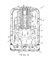
- the dual spool retractor with pretensioner 11 includes the pretensioner structure 12 secured to the dual spool retractor 13, retractor frame 13a.
- the retractor frame 13a is generally channel-shaped, includes two upstanding and spaced flanges 14 and 15 joined in the mounting web of the frame 13a and these flanges 14 and 15 provide journal support for the reels 16 and their shafts 17 which extend therethrough.
- the webbing 18 on the reels 16 is trained away from the frame 13a in paths determined by the selected deployment of the webbing 18.
- the spacer tube 19 assures desired strength in the flanges 14 and 15 of the frame 13a to prevent deformation or collapse of the frame 13a.
- the tubes 19 are secured in compression relation between flanges 14 and 15 by the bolts 20.
- the shafts 17 extend outboard of the retractor frame 13a and project into the pretensioner case 12a.
- the shafts 17 In passage through the case 12a at the flange 15, they are supported by a journal or bushing element 21 and the outboard extension of the shafts 17 in the pretensioner case 12a is supported in the outboard bushing or bearing 22.
- Intermediate the ends of the shafts 17 is a knurled portion 23.
- the knurled portion 23 forms tooth-like integral projections or crests and intermediate dips or roots.
- the knurled portions 23 present cylindrical upset surfaces with substantially increased frictional coefficients over the main portions of the shafts 17.
- the shafts 17 are in spaced-apart adjacent journalled relation and the diametrical slot 24 in the end of the shafts 17 will be understood to be operably attached to a retractor spring (not shown) and normally urging the reels 16 to pick up the webbing 18 when it is relaxed or in release of any spring lock-out structure.
- the axes of the two shafts 17 are offset from each other but are in spaced-apart adjacent parallelity.
- the bolts 25 provide means to removably fasten the pretensioner case 12a to the flange 15 of the frame 13a.
- the pretensioner case 12a is a shallow shell 26 which is closed by the cover 27 of the case 12a.
- the cover 27 is apertured to support the bushings 22 and support shafts 17.
- the case 12a includes piston guide means, as will be seen, and the cover 27 also is provided with piston guide means better visualized in the Figure 2.
- the cover 27 is screwed to the shell 26 by the screws 28.
- a piston 29 is positioned in the shell 26 in case 12a intermediately poised between the shafts 17.
- the piston 29 includes a cylindrical hollow portion or chamber 30.
- the chamber 30 is movable on a tubular sleeve 31 and the tubular sleeve 31 butts against the pretensioner case wall 32.
- the end of the sleeve 31 adjacent the case wall 32 is internally threaded and into the threaded opening is a matingly threaded pyrotechnic cartridge 33.
- the cartridge 33 thus is removable and extends into the chamber 30.
- the cartridge 33 includes a flanged head 34 and an annular seal 35 which seals against the cartridge opening 36. This provides a gas-tight seal in prevention of the pyrotechnic generated gases escaping through the cartridge opening 36.
- Initiator wires 37 extend from cartridge 33 and are attached to an initiator such as an electrical squib potted in the cartridge 33.
- the electrical leads 37 are attached to an electrical source in a circuit closed by a suitable sensor and the sensor and circuit are not a part of the present invention.
- the lower end-of the piston 29 is closed so that the chamber 30 is allowed to expand as the pressure of the pyrotechnic generated gas from the cartridge 33 drives the piston 29 (downwardly as shown in Figure 1) in its guides in the case 12a and cover 27 journalled on the tubular sleeve 31.
- the surfaces 38 and 39 on the piston 29 are in interference fit with the knurled portion 23 of the shafts 17 and this relationship is better understood by reference to Figure 2.
- the 0-ring-like seal 47 restricts blow back of gases between the sleeve 31 and piston 29.
- the arrow in the Figure 3 on the extended axis of the chamber 30 designates the direction of movement of the piston 29 as the gases expand.
- the phantom line discloses the deformation of the piston 29 at the surfaces 39 and 38 in the forming of a tooth-like pattern 48 as the movement of the piston 29 imparts positive rotation of the shafts 17 driven at the knurled portions 23.
- the shafts 17 are hard material such as steel.
- the material forming the lands and surfaces 38 and 39 are of a softer and deformable material such as aluminum, bronzes, brasses, and even lead and alloys or mixes of these to create the formation of teeth as shown as opposed to stripping or shearing in the interference movement between piston 29 and shafts 17. This is somewhat a function of the drive velocity of the piston 29 and hence dependent upon the selected pyrotechnic charge.
- the lands and surfaces 38 and 39 may be inserts fixed to the body of the piston 29 or preferably the surfaces 38 and 39 are integral with the piston 29 as shown. As will be appreciated by varying the length of the lands 38 and 39, the effective length of driving stroke may be varied.
- the cover 27 is appreciated as closing the pretensioner case 12a by attachment thereto by the screws 28 in the perimeter receiving openings 50 as shown.
- the bumper 46 cushions the impact of the piston 29 with the lower wall of the pretensioner case 12a or any selected stop.
- a new or reconditioned pretensioner 12 is replaceable by simple removal of the pretensioner case 12a from the flange 15 by removal of the bolts 25 and without tampering with the retractor portion 13.
- the lobe portion 42 of the piston 29 is then in guide relation with the drop portion 40 of the cover 27 as formed by the raised ribs 51 which flank the travel path of the piston 29 and secure the piston 29 in a journal relation against chance cocking or misalignment as it drives the interference surfaces 38 and 39 into deforming contact against the knurled portions 23 of the shafts 17.
- the dual spool pretensioner In use, the dual spool pretensioner has achieved excellent, performance where it is used with passive restraint harness in rewinding slack in long harness lines at the point of emergency and consequently minimizing the shock to users of webbing where slack or elongation provides hazards. This allows the use of lighter retraction force to maximize user comfort under normal vehicle operating conditions.
- the simplicity of using a single pretensioner to act on dual spools or reels is unique, and the positive drive through tooth formation deformation of the piston is regarded as innovative.
- the ease of unit replacement has made the device attractive in automotive applications and the reconditioning of the unit by substituting a new cartridge and piston has brought about substantial economies.
- the structure used with dual spool retractors admits of design variants to meet required or selected sequencing or delay without regard to radical revision of the existing dual spool retractors.
Landscapes
- Engineering & Computer Science (AREA)
- Mechanical Engineering (AREA)
- Health & Medical Sciences (AREA)
- General Health & Medical Sciences (AREA)
- Business, Economics & Management (AREA)
- Emergency Management (AREA)
- Automotive Seat Belt Assembly (AREA)
Applications Claiming Priority (2)
| Application Number | Priority Date | Filing Date | Title |
|---|---|---|---|
| US238070 | 1981-03-02 | ||
| US06/238,070 US4434953A (en) | 1981-03-02 | 1981-03-02 | Dual spool pretensioner |
Publications (3)
| Publication Number | Publication Date |
|---|---|
| EP0059643A2 true EP0059643A2 (fr) | 1982-09-08 |
| EP0059643A3 EP0059643A3 (en) | 1982-11-17 |
| EP0059643B1 EP0059643B1 (fr) | 1985-05-29 |
Family
ID=22896372
Family Applications (1)
| Application Number | Title | Priority Date | Filing Date |
|---|---|---|---|
| EP82301064A Expired EP0059643B1 (fr) | 1981-03-02 | 1982-03-02 | Pré-tendeur pour bobines jumelées |
Country Status (7)
| Country | Link |
|---|---|
| US (1) | US4434953A (fr) |
| EP (1) | EP0059643B1 (fr) |
| JP (1) | JPS57148962A (fr) |
| KR (1) | KR890000510B1 (fr) |
| AU (1) | AU542490B2 (fr) |
| CA (1) | CA1173420A (fr) |
| DE (1) | DE3263844D1 (fr) |
Cited By (5)
| Publication number | Priority date | Publication date | Assignee | Title |
|---|---|---|---|---|
| EP0629531A1 (fr) * | 1993-06-02 | 1994-12-21 | HS Technik und Design Technische Entwicklungen GmbH | Dispositif d'entraînement pyrotechnique en rotation d'une bobine d'enrouleur automatique de ceinture de sécurité |
| EP0640516A1 (fr) * | 1993-08-26 | 1995-03-01 | TRW Occupant Restraint Systems GmbH | Dispositif pour fixer une cartouche de générateur de gaz de forme essentiellement cylindrique dans une unité d'entraînement de tendeur de ceinture de sécurité |
| WO1995027637A1 (fr) * | 1994-04-07 | 1995-10-19 | Alliedsignal Limited | Pretensionneur pour enrouleur de ceinture de securite |
| EP0649779A3 (fr) * | 1993-10-25 | 1996-03-06 | Trw Repa Gmbh | Dispositif tendeur pour systèmes de retenue à ceinture de sécurité pour véhicules. |
| US8207391B2 (en) * | 2004-06-07 | 2012-06-26 | National Institute For Materials Science | Adsorbent for radioelement-containing waste and method for fixing radioelement |
Families Citing this family (18)
| Publication number | Priority date | Publication date | Assignee | Title |
|---|---|---|---|---|
| DE3532407A1 (de) * | 1985-09-11 | 1987-03-12 | Autoflug Gmbh | Sitzintegriertes sicherheitsgurtsystem |
| DE3621622A1 (de) * | 1986-06-27 | 1988-01-21 | Trw Repa Gmbh | Gurtstraffer an einem sicherheitsgurtaufroller |
| US5074074A (en) * | 1990-10-31 | 1991-12-24 | Yeadon Alan W | Compact gun unplugging device |
| JPH05162614A (ja) * | 1991-12-17 | 1993-06-29 | Takata Kk | リトラクタ軸回転式プリテンショナ |
| DE4222993A1 (de) * | 1992-07-13 | 1994-01-20 | Trw Repa Gmbh | Gurtaufroller mit einem an der Gurtspule angreifenden Gurtstraffer |
| US5624083A (en) * | 1992-07-13 | 1997-04-29 | Trw Repa Gmbh | Belt retractor with a belt pretensioner acting on the belt drum |
| DE4225218A1 (de) * | 1992-07-30 | 1994-02-03 | Takata Europ Gmbh | Gurtstraffer bei Sicherheitsgurtanordnungen in Kraftfahrzeugen |
| US5397075A (en) * | 1993-09-10 | 1995-03-14 | Automotive Systems Laboratory, Inc. | Seat belt pretensioner |
| DE4404462A1 (de) * | 1994-02-11 | 1995-08-17 | Trw Repa Gmbh | Gurtstraffer für einen Sicherheitsgurt |
| JP3322773B2 (ja) * | 1994-07-06 | 2002-09-09 | エヌエスケー・オートリブ株式会社 | プリテンショナー付きシートベルト用リトラクター |
| US5553803A (en) * | 1994-09-13 | 1996-09-10 | Takata Vehicle Safety Technology Gmbh | Belt tensioner for safety belts for motor vehicles |
| US5839686A (en) * | 1995-10-12 | 1998-11-24 | Alliedsignal Inc. | Chain driven pretensioner and retractor |
| US5906327A (en) * | 1998-02-17 | 1999-05-25 | Breed Automotive Technology, Inc. | Pretensioner or belt tightener |
| GB9808610D0 (en) * | 1998-04-22 | 1998-06-24 | Breed Automotive Tech | Pretensioner |
| US7011341B2 (en) * | 2003-06-27 | 2006-03-14 | Trw Vehicle Safety Systems Inc. | Four-point vehicle occupant restraint system with linked lap belt retractors |
| US6877728B2 (en) * | 2003-09-04 | 2005-04-12 | Lakin Manufacturing Corporation | Suspension assembly having multiple torsion members which cooperatively provide suspension to a wheel |
| US20060172833A1 (en) * | 2005-02-02 | 2006-08-03 | Kitzmiller James A | Drive band tensioner having a force transmitting assembly with one or more elastic biasing members |
| US7401815B2 (en) * | 2005-03-17 | 2008-07-22 | Antoliv Asp, Inc. | Dual spool retractor seat belt system |
Citations (8)
| Publication number | Priority date | Publication date | Assignee | Title |
|---|---|---|---|---|
| US3189296A (en) * | 1963-05-15 | 1965-06-15 | Pacific Scientific Co | Safety harness device |
| US3335975A (en) * | 1965-11-09 | 1967-08-15 | Gen Dynamics Corp | Safety device |
| US3386683A (en) * | 1966-02-10 | 1968-06-04 | Mc Donnell Douglas Corp | Power retraction inertia reel |
| DE2409943A1 (de) * | 1973-03-02 | 1974-09-19 | Nissan Motor | Sitz fuer ein kraftfahrzeug |
| US3871470A (en) * | 1972-05-12 | 1975-03-18 | Volkswagenwerk Ag | Safety belt tensioning device |
| FR2269651A1 (fr) * | 1974-05-03 | 1975-11-28 | Dynamit Nobel Ag | |
| FR2286730A1 (fr) * | 1974-10-03 | 1976-04-30 | Foerenade Fabriksverken | Ceinture de securite pour vehicule |
| DE2505625A1 (de) * | 1975-02-11 | 1976-08-19 | Volkswagenwerk Ag | Sicherheitseinrichtung fuer fahrzeuge, insbesondere kraftfahrzeuge |
Family Cites Families (1)
| Publication number | Priority date | Publication date | Assignee | Title |
|---|---|---|---|---|
| JPS5521696U (fr) * | 1978-07-31 | 1980-02-12 |
-
1981
- 1981-03-02 US US06/238,070 patent/US4434953A/en not_active Expired - Lifetime
- 1981-11-25 AU AU77862/81A patent/AU542490B2/en not_active Ceased
-
1982
- 1982-01-28 CA CA000395147A patent/CA1173420A/fr not_active Expired
- 1982-01-28 JP JP57011046A patent/JPS57148962A/ja active Granted
- 1982-02-20 KR KR8200745A patent/KR890000510B1/ko not_active IP Right Cessation
- 1982-03-02 EP EP82301064A patent/EP0059643B1/fr not_active Expired
- 1982-03-02 DE DE8282301064T patent/DE3263844D1/de not_active Expired
Patent Citations (8)
| Publication number | Priority date | Publication date | Assignee | Title |
|---|---|---|---|---|
| US3189296A (en) * | 1963-05-15 | 1965-06-15 | Pacific Scientific Co | Safety harness device |
| US3335975A (en) * | 1965-11-09 | 1967-08-15 | Gen Dynamics Corp | Safety device |
| US3386683A (en) * | 1966-02-10 | 1968-06-04 | Mc Donnell Douglas Corp | Power retraction inertia reel |
| US3871470A (en) * | 1972-05-12 | 1975-03-18 | Volkswagenwerk Ag | Safety belt tensioning device |
| DE2409943A1 (de) * | 1973-03-02 | 1974-09-19 | Nissan Motor | Sitz fuer ein kraftfahrzeug |
| FR2269651A1 (fr) * | 1974-05-03 | 1975-11-28 | Dynamit Nobel Ag | |
| FR2286730A1 (fr) * | 1974-10-03 | 1976-04-30 | Foerenade Fabriksverken | Ceinture de securite pour vehicule |
| DE2505625A1 (de) * | 1975-02-11 | 1976-08-19 | Volkswagenwerk Ag | Sicherheitseinrichtung fuer fahrzeuge, insbesondere kraftfahrzeuge |
Cited By (5)
| Publication number | Priority date | Publication date | Assignee | Title |
|---|---|---|---|---|
| EP0629531A1 (fr) * | 1993-06-02 | 1994-12-21 | HS Technik und Design Technische Entwicklungen GmbH | Dispositif d'entraînement pyrotechnique en rotation d'une bobine d'enrouleur automatique de ceinture de sécurité |
| EP0640516A1 (fr) * | 1993-08-26 | 1995-03-01 | TRW Occupant Restraint Systems GmbH | Dispositif pour fixer une cartouche de générateur de gaz de forme essentiellement cylindrique dans une unité d'entraînement de tendeur de ceinture de sécurité |
| EP0649779A3 (fr) * | 1993-10-25 | 1996-03-06 | Trw Repa Gmbh | Dispositif tendeur pour systèmes de retenue à ceinture de sécurité pour véhicules. |
| WO1995027637A1 (fr) * | 1994-04-07 | 1995-10-19 | Alliedsignal Limited | Pretensionneur pour enrouleur de ceinture de securite |
| US8207391B2 (en) * | 2004-06-07 | 2012-06-26 | National Institute For Materials Science | Adsorbent for radioelement-containing waste and method for fixing radioelement |
Also Published As
| Publication number | Publication date |
|---|---|
| EP0059643A3 (en) | 1982-11-17 |
| AU542490B2 (en) | 1985-02-21 |
| JPH0247378B2 (fr) | 1990-10-19 |
| US4434953A (en) | 1984-03-06 |
| EP0059643B1 (fr) | 1985-05-29 |
| DE3263844D1 (en) | 1985-07-04 |
| CA1173420A (fr) | 1984-08-28 |
| KR830008690A (ko) | 1983-12-14 |
| KR890000510B1 (ko) | 1989-03-20 |
| AU7786281A (en) | 1982-09-09 |
| JPS57148962A (en) | 1982-09-14 |
Similar Documents
| Publication | Publication Date | Title |
|---|---|---|
| EP0059643B1 (fr) | Pré-tendeur pour bobines jumelées | |
| EP1165351B1 (fr) | Dispositif de pre-tension pour ceinture de securite | |
| US7350734B2 (en) | Seat belt pretensioner | |
| US5641131A (en) | Combined seat belt retractor and tensioner unit | |
| US8220735B2 (en) | Adaptive load limiting retractor | |
| US6505790B2 (en) | Pretensioner device | |
| CN110077358B (zh) | 安全带预张紧牵引器组件 | |
| CN110520336A (zh) | 包括活塞安全阀构件的安全带预紧式卷收器组件 | |
| JP7213843B2 (ja) | リトラクタプリテンショナアセンブリ | |
| WO1997013661A1 (fr) | Enrouleur et pretendeur entraine par une chaine | |
| EP0827883A2 (fr) | Tendeur de ceinture | |
| JPH03153441A (ja) | 自動車用の安全ベルト抑止装置のための緊張手段 | |
| EP1201513B1 (fr) | Actionneur à piston à déclenchement progressif | |
| EP0600689B1 (fr) | Rétracteur de ceinture de sécurité à prétensionneur | |
| US5489072A (en) | Seat belt retractor with pre-tensioner | |
| US20120049500A1 (en) | Dual Stage Pretensioning and High Pay-In Capacity Pretensioning Retractor | |
| CN115461253B (zh) | 卷收器预紧器组件 | |
| JP4248106B2 (ja) | シートベルト装置 | |
| DE4127958A1 (de) | Rueckstrammervorrichtung zum straffen eines sicherheitsgurtes in einem kraftfahrzeug | |
| RU2116902C1 (ru) | Устройство для упреждающего натяжения лямки ремня безопасности транспортного средства | |
| WO2006044541A2 (fr) | Pretendeur de ceinture de securite | |
| CN117818527A (zh) | 一种预紧限力卷收器及安全带装置 | |
| EP1286868A1 (fr) | Pre-tendeur | |
| KR20030028144A (ko) | 안전벨트 리트랙터의 릴역회전장치 |
Legal Events
| Date | Code | Title | Description |
|---|---|---|---|
| PUAI | Public reference made under article 153(3) epc to a published international application that has entered the european phase |
Free format text: ORIGINAL CODE: 0009012 |
|
| AK | Designated contracting states |
Designated state(s): DE FR GB IT SE |
|
| PUAL | Search report despatched |
Free format text: ORIGINAL CODE: 0009013 |
|
| AK | Designated contracting states |
Designated state(s): DE FR GB IT SE |
|
| 17P | Request for examination filed |
Effective date: 19830308 |
|
| RAP1 | Party data changed (applicant data changed or rights of an application transferred) |
Owner name: TRW AUTOMOTIVE PRODUCTS, INC. |
|
| ITF | It: translation for a ep patent filed |
Owner name: DR. ING. A. RACHELI & C. |
|
| GRAA | (expected) grant |
Free format text: ORIGINAL CODE: 0009210 |
|
| AK | Designated contracting states |
Designated state(s): DE FR GB IT SE |
|
| REF | Corresponds to: |
Ref document number: 3263844 Country of ref document: DE Date of ref document: 19850704 |
|
| ET | Fr: translation filed | ||
| PLBE | No opposition filed within time limit |
Free format text: ORIGINAL CODE: 0009261 |
|
| STAA | Information on the status of an ep patent application or granted ep patent |
Free format text: STATUS: NO OPPOSITION FILED WITHIN TIME LIMIT |
|
| 26N | No opposition filed | ||
| REG | Reference to a national code |
Ref country code: FR Ref legal event code: TP |
|
| ITPR | It: changes in ownership of a european patent |
Owner name: CESSIONE;TRW VEHICLE SAFETY SYSTEMS INC. |
|
| REG | Reference to a national code |
Ref country code: GB Ref legal event code: 732 |
|
| PGFP | Annual fee paid to national office [announced via postgrant information from national office to epo] |
Ref country code: SE Payment date: 19910130 Year of fee payment: 10 |
|
| PGFP | Annual fee paid to national office [announced via postgrant information from national office to epo] |
Ref country code: FR Payment date: 19910219 Year of fee payment: 10 |
|
| ITTA | It: last paid annual fee | ||
| PGFP | Annual fee paid to national office [announced via postgrant information from national office to epo] |
Ref country code: GB Payment date: 19920120 Year of fee payment: 11 |
|
| PG25 | Lapsed in a contracting state [announced via postgrant information from national office to epo] |
Ref country code: SE Effective date: 19920303 |
|
| PG25 | Lapsed in a contracting state [announced via postgrant information from national office to epo] |
Ref country code: FR Effective date: 19921130 |
|
| REG | Reference to a national code |
Ref country code: FR Ref legal event code: ST |
|
| PG25 | Lapsed in a contracting state [announced via postgrant information from national office to epo] |
Ref country code: GB Effective date: 19930302 |
|
| GBPC | Gb: european patent ceased through non-payment of renewal fee |
Effective date: 19930302 |
|
| EUG | Se: european patent has lapsed |
Ref document number: 82301064.0 Effective date: 19921005 |
|
| PGFP | Annual fee paid to national office [announced via postgrant information from national office to epo] |
Ref country code: DE Payment date: 20010228 Year of fee payment: 20 |