EP0057272B1 - Pale d'hélice en construction de coquille - Google Patents
Pale d'hélice en construction de coquille Download PDFInfo
- Publication number
- EP0057272B1 EP0057272B1 EP81109734A EP81109734A EP0057272B1 EP 0057272 B1 EP0057272 B1 EP 0057272B1 EP 81109734 A EP81109734 A EP 81109734A EP 81109734 A EP81109734 A EP 81109734A EP 0057272 B1 EP0057272 B1 EP 0057272B1
- Authority
- EP
- European Patent Office
- Prior art keywords
- shell
- blade
- edge portion
- root
- rotor blade
- Prior art date
- Legal status (The legal status is an assumption and is not a legal conclusion. Google has not performed a legal analysis and makes no representation as to the accuracy of the status listed.)
- Expired
Links
- 238000010276 construction Methods 0.000 title claims description 6
- 239000000835 fiber Substances 0.000 claims description 26
- 229920002430 Fibre-reinforced plastic Polymers 0.000 claims description 4
- 239000011151 fibre-reinforced plastic Substances 0.000 claims description 4
- 230000007704 transition Effects 0.000 claims description 3
- 239000000463 material Substances 0.000 claims 2
- 238000000034 method Methods 0.000 claims 1
- 238000004519 manufacturing process Methods 0.000 description 3
- 230000005540 biological transmission Effects 0.000 description 2
- 239000004918 carbon fiber reinforced polymer Substances 0.000 description 1
- 230000003247 decreasing effect Effects 0.000 description 1
- 230000001419 dependent effect Effects 0.000 description 1
- 230000002349 favourable effect Effects 0.000 description 1
- 239000011152 fibreglass Substances 0.000 description 1
- 239000006260 foam Substances 0.000 description 1
- 238000010030 laminating Methods 0.000 description 1
- 239000004033 plastic Substances 0.000 description 1
- 229920003023 plastic Polymers 0.000 description 1
Images
Classifications
-
- F—MECHANICAL ENGINEERING; LIGHTING; HEATING; WEAPONS; BLASTING
- F04—POSITIVE - DISPLACEMENT MACHINES FOR LIQUIDS; PUMPS FOR LIQUIDS OR ELASTIC FLUIDS
- F04D—NON-POSITIVE-DISPLACEMENT PUMPS
- F04D29/00—Details, component parts, or accessories
- F04D29/26—Rotors specially for elastic fluids
- F04D29/32—Rotors specially for elastic fluids for axial flow pumps
- F04D29/38—Blades
- F04D29/388—Blades characterised by construction
-
- B—PERFORMING OPERATIONS; TRANSPORTING
- B64—AIRCRAFT; AVIATION; COSMONAUTICS
- B64C—AEROPLANES; HELICOPTERS
- B64C27/00—Rotorcraft; Rotors peculiar thereto
- B64C27/32—Rotors
- B64C27/46—Blades
- B64C27/473—Constructional features
-
- F—MECHANICAL ENGINEERING; LIGHTING; HEATING; WEAPONS; BLASTING
- F03—MACHINES OR ENGINES FOR LIQUIDS; WIND, SPRING, OR WEIGHT MOTORS; PRODUCING MECHANICAL POWER OR A REACTIVE PROPULSIVE THRUST, NOT OTHERWISE PROVIDED FOR
- F03D—WIND MOTORS
- F03D1/00—Wind motors with rotation axis substantially parallel to the air flow entering the rotor
- F03D1/06—Rotors
- F03D1/065—Rotors characterised by their construction elements
- F03D1/0658—Arrangements for fixing wind-engaging parts to a hub
-
- B—PERFORMING OPERATIONS; TRANSPORTING
- B64—AIRCRAFT; AVIATION; COSMONAUTICS
- B64C—AEROPLANES; HELICOPTERS
- B64C27/00—Rotorcraft; Rotors peculiar thereto
- B64C27/32—Rotors
- B64C27/46—Blades
- B64C27/473—Constructional features
- B64C2027/4733—Rotor blades substantially made from particular materials
- B64C2027/4736—Rotor blades substantially made from particular materials from composite materials
-
- F—MECHANICAL ENGINEERING; LIGHTING; HEATING; WEAPONS; BLASTING
- F05—INDEXING SCHEMES RELATING TO ENGINES OR PUMPS IN VARIOUS SUBCLASSES OF CLASSES F01-F04
- F05B—INDEXING SCHEME RELATING TO WIND, SPRING, WEIGHT, INERTIA OR LIKE MOTORS, TO MACHINES OR ENGINES FOR LIQUIDS COVERED BY SUBCLASSES F03B, F03D AND F03G
- F05B2240/00—Components
- F05B2240/20—Rotors
- F05B2240/30—Characteristics of rotor blades, i.e. of any element transforming dynamic fluid energy to or from rotational energy and being attached to a rotor
-
- Y—GENERAL TAGGING OF NEW TECHNOLOGICAL DEVELOPMENTS; GENERAL TAGGING OF CROSS-SECTIONAL TECHNOLOGIES SPANNING OVER SEVERAL SECTIONS OF THE IPC; TECHNICAL SUBJECTS COVERED BY FORMER USPC CROSS-REFERENCE ART COLLECTIONS [XRACs] AND DIGESTS
- Y02—TECHNOLOGIES OR APPLICATIONS FOR MITIGATION OR ADAPTATION AGAINST CLIMATE CHANGE
- Y02E—REDUCTION OF GREENHOUSE GAS [GHG] EMISSIONS, RELATED TO ENERGY GENERATION, TRANSMISSION OR DISTRIBUTION
- Y02E10/00—Energy generation through renewable energy sources
- Y02E10/70—Wind energy
- Y02E10/72—Wind turbines with rotation axis in wind direction
Definitions
- the invention relates to a rotor blade according to the preamble of claim 1, in particular for fans or fans of the largest dimensions, large wind turbines and the like.
- tension bolts For such rotor blades, an articulated connection to the rotor hub by means of tension-loaded bolts (so-called tension bolts) is preferred. So far, however, such a blade connection, if one wanted to get by without additional fitting for the shell root, had to be limited to training the blade shell in shell construction with a soft support core with respect to tensile forces between two cover skins made of fiber-reinforced plastic (DE-OS 28 32 098). Apart from this, the large wind turbines or their rotors, which require a blade pitch adjustment option, are dependent on an additional flange-like bearing intermediate piece adapted to the ring shape of the blade angle bearing because of the wing profile of the shell root. That is u. a. undesirable for reasons of lightweight construction.
- Such an intermediate piece can be dispensed with in the case of a wing provided with an annular connection end in accordance with CH-A-369 589, but instead the fiber strands have to be folded over into loop-shaped connection eyes, which in turn form a connection flange as a whole. This requires considerable manufacturing effort.
- the invention has for its object to design a rotor blade of the type mentioned for an articulated connection to the rotor hub so that a tie bolt connection can be produced directly between the shell root and a blade angle bearing.
- the arched trailing edge section has an increasing width from the leaf wing or its trailing edge section to the annular connecting end (claim 4).
- the arched trailing edge section has an increasing width from the leaf wing or its trailing edge section to the annular connecting end (claim 4).
- the rotor blade according to the invention also fulfills the requirement for a streamlined blade shape also in the area of the blade root, namely because of the relatively large width of the arched trailing edge portion relative to the (blade) profile depth; this favorable flow form can be completed in a simple manner by angular transitions between the curved surface trailing edge section and the remaining leaf shell sections (claim 6).
- this rotor blade design in a fiber-friendly design has the advantage that the draw bolts required for the blade connection can be easily pre-tensioned to ensure a constant minimum stiffness of the blade connection during operation;
- the preferred embodiments of the invention according to claims 7 and 8 are of particular importance for safety reasons.
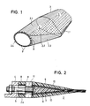
- FIG. 1 The partial representation of a rotor blade or its blade shell made of fiber-reinforced plastic according to FIG. 1 should in particular clarify that a (blade) shell root 2 adjoining the blade wing 1 for the flatten connection to an annular or disc-shaped flange 4 (FIG. 2) from a unwindable surface is formed, which can be made up of several individual surfaces during manufacture, for example in a laminating mold, namely from a (shell root) leading edge section 2.1 and an intermediate section 2.2 (on each side of the sheet) and a trailing edge section 2.3 these areas in the longitudinal and transverse direction of the guide lines.
- a (blade) shell root 2 adjoining the blade wing 1 for the flatten connection to an annular or disc-shaped flange 4 (FIG. 2) from a unwindable surface is formed, which can be made up of several individual surfaces during manufacture, for example in a laminating mold, namely from a (shell root) leading edge section 2.1 and an intermediate section 2.2 (on each side of
- the load-bearing area of the leaf shell namely the leaf leading edge (leaf nose) 3 is formed from unidirectional fiber strands which extend in the longitudinal direction of the leaf and extend beyond the leaf leading edge region of the leaf wing 1 into the shell root 2 and thereby on the structure of the (shell root ) Terminal 2.4 about two Contribute thirds.
- the rest of the cross-section of the connection end 2.4 is filled by the unidirectional fiber strands - which are therefore arch-shaped - trailing edge section 2.3 of the shell root 2, so that the connection end 2.4 finally has a completely unidirectional (homogeneous) fiber structure.
- an intermediate section 2.2 which has a crosswise fiber orientation and thus becomes effective for a power transmission from the trailing edge section 2.3 into the load-bearing leading edge section 2.1 (by thrust)
- a corresponding area of an outer sheet cover which is otherwise not shown, can function, for production reasons, which (also) the unidirectional fiber strands covered.
- the arched trailing edge section 2.3 has a width increasing from the leaf wing 1 to the annular connecting end 2.4, the unidirectional fiber strands which end in the course of this trailing edge section 2.3 in front of the trailing leaf trailing edge section 1.1 will contribute to the power transmission via the intermediate section 2.2 into the leading edge section 2.1 and will furthermore contribute to the Leaf wing trailing edge section 1.1 extending unidirectional fiber strands additionally increase the leaf stiffness in the leaf pivoting direction.
- the connection of the shell root 2 2 or its circular connection end 2.4 to the aforementioned flange 4 is made via tie bolts 5.
- the unidirectional fiber strands are divided into two layers 6, one above the other, preferably of the same thickness, the interspace being a wedge-shaped core filling 7, e.g. B. from foam plastic, in which 8 passages 9 are left for free access of the tie bolts 5 to cross holes.
- a wedge-shaped core filling 7 e.g. B. from foam plastic
- connection of the respective pull bolt which is finally produced via a bolt 11 seated in the respective transverse bore 8 with the shell root 2 has the advantage that it can be placed under prestress.
- expansion bolts are used as tension bolts 5, as shown, so that the associated cross-bore bolt 11 need only have a transverse threaded bore for this connection.
Claims (8)
Applications Claiming Priority (2)
| Application Number | Priority Date | Filing Date | Title |
|---|---|---|---|
| DE3103710 | 1981-02-04 | ||
| DE3103710A DE3103710C2 (de) | 1981-02-04 | 1981-02-04 | "Rotor in Schalenbauweise" |
Publications (3)
| Publication Number | Publication Date |
|---|---|
| EP0057272A2 EP0057272A2 (fr) | 1982-08-11 |
| EP0057272A3 EP0057272A3 (en) | 1982-09-01 |
| EP0057272B1 true EP0057272B1 (fr) | 1984-02-08 |
Family
ID=6124000
Family Applications (1)
| Application Number | Title | Priority Date | Filing Date |
|---|---|---|---|
| EP81109734A Expired EP0057272B1 (fr) | 1981-02-04 | 1981-11-17 | Pale d'hélice en construction de coquille |
Country Status (4)
| Country | Link |
|---|---|
| US (1) | US4412784A (fr) |
| EP (1) | EP0057272B1 (fr) |
| DE (1) | DE3103710C2 (fr) |
| ES (1) | ES8302209A1 (fr) |
Families Citing this family (63)
| Publication number | Priority date | Publication date | Assignee | Title |
|---|---|---|---|---|
| US5222866A (en) * | 1988-09-30 | 1993-06-29 | Societe Europeenne De Propulsion | High speed composite turbine wheel |
| DE3922199C1 (en) * | 1989-07-06 | 1990-07-19 | Messerschmitt-Boelkow-Blohm Gmbh, 8012 Ottobrunn, De | Shell-type blade root for wind energy rotor - is angularly and pivotably connected with tubular centre body of rotor to encircling hub via wedge-connected roller bearing |
| US5171099A (en) * | 1990-11-01 | 1992-12-15 | The Boeing Company | Apparatus to attach a sandwich panel |
| DE4335221C1 (de) * | 1993-10-15 | 1995-03-16 | Deutsche Forsch Luft Raumfahrt | Rotorblatt für Windkraftanlagen |
| NL1001200C2 (nl) * | 1995-09-15 | 1997-03-20 | Aerpac Special Products B V | Molenwiek. |
| US5660527A (en) * | 1995-10-05 | 1997-08-26 | The Wind Turbine Company | Wind turbine rotor blade root end |
| DE19733372C1 (de) * | 1997-08-01 | 1999-01-07 | Aloys Wobben | Rotorblatt und Rotor einer Windenergieanlage |
| NL1015558C2 (nl) * | 2000-06-28 | 2002-01-08 | Stichting En Onderzoek Ct Nede | Blad van een windturbine. |
| FR2821129B1 (fr) | 2001-02-22 | 2003-05-16 | Eads Airbus Sa | Dispositif d'assemblage d'un panneau et d'une structure, apte a transmettre des efforts importants |
| FR2832668B1 (fr) * | 2001-11-26 | 2004-02-13 | Airbus France | Procede de fabrication d'un ensemble en materiau composite et voilure et element stabilisateur d'aeronef obtenus par ce procede |
| DE10224439C5 (de) * | 2002-06-01 | 2009-12-31 | Aloys Wobben | Verfahren zur Montage/Demontage von Komponenten einer Windenergieanlage |
| DE10303555B4 (de) * | 2003-01-29 | 2007-01-25 | Aloys Wobben | Verfahren zur kranlosen Montage eines Rotorblattes einer Windenergieanlage |
| DE10324166B4 (de) * | 2003-05-28 | 2005-05-04 | Aloys Wobben | Rotorblattanschluss |
| EP1486415A1 (fr) * | 2003-06-12 | 2004-12-15 | SSP Technology A/S | Pale de turbine éolienne et procédé de fabrication de la base d'une pale d'éolienne |
| US7438533B2 (en) | 2005-12-15 | 2008-10-21 | General Electric Company | Wind turbine rotor blade |
| DE102006014742B4 (de) * | 2006-03-30 | 2008-01-24 | Nordex Energy Gmbh | Rotorblatt für Windenergieanlagen |
| US7517194B2 (en) * | 2006-04-30 | 2009-04-14 | General Electric Company | Rotor blade for a wind turbine |
| DE102006022272C5 (de) * | 2006-05-11 | 2013-07-25 | Repower Systems Ag | Rotorblattanschluss |
| DE102006022279B4 (de) * | 2006-05-11 | 2016-05-12 | Aloys Wobben | Rotorblatt für eine Windenergieanlage |
| DE102007008167C5 (de) * | 2007-02-14 | 2016-07-07 | Nordex Energy Gmbh | Windenergieanlage mit einer Rotornabe |
| WO2008107738A1 (fr) * | 2007-03-06 | 2008-09-12 | Tecsis Tecnologia E Sistemas Avançados Ltda | Fixation de pale de ventilateur |
| ITTO20070666A1 (it) * | 2007-09-24 | 2009-03-25 | Blue H Intellectual Properties | Sistema di conversione di energia eolica offshore per acque profonde |
| EP2078851A1 (fr) * | 2008-01-14 | 2009-07-15 | Lm Glasfiber A/S | Pale d'éolienne et assemblage de moyeu |
| GB2462307A (en) * | 2008-08-01 | 2010-02-03 | Vestas Wind Sys As | Extension portion for wind turbine blade |
| GB2462308A (en) * | 2008-08-01 | 2010-02-03 | Vestas Wind Sys As | Extension portion for wind turbine blade |
| GB2465167A (en) * | 2008-11-07 | 2010-05-12 | Vestas Wind Sys As | A turbine blade having mounting inserts of different lengths |
| AU2009322104B2 (en) | 2008-12-05 | 2014-07-10 | Vestas Wind Systems A/S | Efficient wind turbine blades, wind turbine blade structures, and associated systems and methods of manufacture, assembly and use |
| GB0822681D0 (en) * | 2008-12-12 | 2009-01-21 | Aviat Entpr Ltd | Rotor blades |
| ES2353325B1 (es) * | 2009-06-23 | 2012-01-25 | Gamesa Innovation & Technology, S.L | Rigidización de la raíz de pala de un aerogenerador. |
| US20110052404A1 (en) * | 2009-08-25 | 2011-03-03 | Zuteck Michael D | Swept blades with enhanced twist response |
| CN102022255A (zh) * | 2009-09-23 | 2011-04-20 | 苏州红枫风电模具有限公司 | 用于风力涡轮机叶片根部的嵌入件 |
| US20110103965A1 (en) * | 2009-10-30 | 2011-05-05 | General Electric Company | Wind turbine blades |
| US20110100540A1 (en) * | 2009-10-30 | 2011-05-05 | General Electric Company | Methods of manufacture of wind turbine blades and other structures |
| US8066490B2 (en) * | 2009-12-21 | 2011-11-29 | General Electric Company | Wind turbine rotor blade |
| US9500179B2 (en) | 2010-05-24 | 2016-11-22 | Vestas Wind Systems A/S | Segmented wind turbine blades with truss connection regions, and associated systems and methods |
| US9623966B1 (en) * | 2010-09-09 | 2017-04-18 | Groen Aeronautics Corporation | Blade root attachment apparatus and method |
| US8950699B1 (en) * | 2010-09-09 | 2015-02-10 | Groen Brothers Aviation, Inc. | Heliplane rotor thermal management for maintaining dimensional stability |
| DE202010013535U1 (de) | 2010-09-24 | 2010-12-02 | Repower Systems Ag | Blattanschluss eines Rotorblatts einer Windenergieanlage |
| US8250761B2 (en) * | 2010-12-13 | 2012-08-28 | General Electric Company | Methods of manufacturing rotor blades for a wind turbine |
| CN103747944B (zh) | 2011-04-11 | 2016-09-07 | Lmwp专利控股有限公司 | 在其根部区域中具有伸长紧固部件的风力涡轮叶片 |
| DE202011100897U1 (de) | 2011-05-17 | 2011-10-14 | Windnovation Engineering Solutions Gmbh | Befestigung von Rotorblättern auf der Nabe von Windenergieanlagen |
| EP2530301A1 (fr) * | 2011-05-31 | 2012-12-05 | General Electric Company | Elément de renforcement de la base d'une pale et procédé d'assemblage de ladite pale du rotor ayant l'élément de renforcement |
| DK2532881T3 (en) * | 2011-06-10 | 2015-01-12 | Siemens Ag | A rotor blade for a wind turbine |
| US8360733B2 (en) | 2011-09-09 | 2013-01-29 | General Electric Company | Rotor blade for a wind turbine and methods of manufacturing the same |
| EP2592264B1 (fr) | 2011-11-11 | 2014-12-31 | Nordex Energy GmbH | Raccord de pale pour une pale de rotor d'une éolienne |
| ES2475491B1 (es) * | 2013-01-10 | 2015-04-17 | Ingeniería Prosix, S.L. | Pala de turbina eólica |
| EP2937557B1 (fr) | 2013-05-17 | 2017-11-15 | Shaikenov, Blok | Roue éolienne (en deux variantes) |
| US9464622B2 (en) * | 2013-05-31 | 2016-10-11 | General Electric Company | Rotor blade assembly having a stiffening root insert |
| US9574544B2 (en) | 2013-12-16 | 2017-02-21 | General Electric Company | Methods of manufacturing rotor blade components for a wind turbine |
| US9709030B2 (en) | 2013-12-16 | 2017-07-18 | General Electric Company | Methods of manufacturing rotor blade components for a wind turbine |
| EP3169895B1 (fr) * | 2014-07-14 | 2019-09-11 | LM WP Patent Holding A/S | Coque d'extension pour pale d'éolienne |
| US10099434B2 (en) * | 2014-09-16 | 2018-10-16 | General Electric Company | Composite airfoil structures |
| DE102014018280A1 (de) * | 2014-12-12 | 2016-06-16 | Rwe Innogy Gmbh | Befestigungsvorrichtung zur Befestigung eines Rotorblattes an einer Rotornabe einer Windkraftanlage |
| ES2768398T3 (es) | 2014-12-19 | 2020-06-22 | Nordex Energy Spain Sau | Pala de aerogenerador y aerogenerador que comprende dicha pala |
| US10145244B2 (en) | 2015-07-06 | 2018-12-04 | Bell Helicopter Textron Inc. | Rotorcraft rotor blade assembly |
| WO2017101943A1 (fr) * | 2015-12-14 | 2017-06-22 | Vestas Wind Systems A/S | Raccord pour relier une pale de rotor de turbine éolienne à un moyeu de rotor et procédé associé |
| ES2897956T3 (es) * | 2016-09-05 | 2022-03-03 | Emprending Business S L L | Procedimiento y equipo para la reparación de raíces de palas de aerogeneradores |
| KR102033366B1 (ko) | 2017-02-14 | 2019-10-17 | 블로크 샤이케노프 | 블레이드 엘보우 굽힘부를 가지는 풍차 |
| US11015570B2 (en) * | 2017-03-01 | 2021-05-25 | General Electric Company | Wind turbine rotor blade root insert with integrated flange member |
| DE102017003061B4 (de) | 2017-03-30 | 2022-11-24 | Albany Engineered Composites, Inc. | Anschlusselement |
| EP3581790A1 (fr) * | 2018-06-14 | 2019-12-18 | Siemens Gamesa Renewable Energy A/S | Pale de rotor d'éolienne |
| CN112912616A (zh) * | 2018-11-01 | 2021-06-04 | 通用电气公司 | 由不相似材料构成的风力涡轮转子叶片连结部 |
| EP3822065A1 (fr) * | 2019-11-14 | 2021-05-19 | Siemens Gamesa Renewable Energy A/S | Procédé de fabrication de sections de segment racine d'une pale de turbine, procédé de fabrication du segment racine et procédé de fabrication de la pale de turbine |
Family Cites Families (7)
| Publication number | Priority date | Publication date | Assignee | Title |
|---|---|---|---|---|
| US1875597A (en) * | 1929-01-10 | 1932-09-06 | American Propeller Company | Propeller |
| CH369589A (de) * | 1958-08-24 | 1963-05-31 | Ulrich Dr Ing Huetter | Verfahren zum Herstellen eines aus mindestens einer faserverstärkten Kunststoffschale oder -platte bestehenden Bauteiles, insbesondere von aero- bzw. hydrodynamischer Form |
| FR2252916B1 (fr) * | 1973-11-30 | 1978-02-24 | Aerospatiale | |
| US4083656A (en) * | 1975-03-21 | 1978-04-11 | Textron, Inc. | Composite rotor blade |
| DE2658876C3 (de) * | 1976-12-24 | 1983-11-10 | Hütter, Ulrich, Prof. Dr.-Ing., 7312 Kirchheim | Schalenkörper, beispielsweise Trag- oder Rotorflügel, in Composite-Bauweise |
| DE2832098C2 (de) * | 1978-07-21 | 1982-06-03 | Messerschmitt-Bölkow-Blohm GmbH, 8000 München | Anordnung zur Zug- bzw. Längskrafteinleitung bei einem Bauteil in Sandwichbauweise |
| US4242160A (en) * | 1979-02-02 | 1980-12-30 | United Technologies Corporation | Method of winding a wind turbine blade using a filament reinforced mandrel |
-
1981
- 1981-02-04 DE DE3103710A patent/DE3103710C2/de not_active Expired
- 1981-11-17 EP EP81109734A patent/EP0057272B1/fr not_active Expired
-
1982
- 1982-01-26 US US06/342,907 patent/US4412784A/en not_active Expired - Fee Related
- 1982-02-03 ES ES509307A patent/ES8302209A1/es not_active Expired
Also Published As
| Publication number | Publication date |
|---|---|
| DE3103710A1 (de) | 1982-08-12 |
| EP0057272A2 (fr) | 1982-08-11 |
| ES509307A0 (es) | 1982-12-16 |
| US4412784A (en) | 1983-11-01 |
| DE3103710C2 (de) | 1983-03-24 |
| EP0057272A3 (en) | 1982-09-01 |
| ES8302209A1 (es) | 1982-12-16 |
Similar Documents
| Publication | Publication Date | Title |
|---|---|---|
| EP0057272B1 (fr) | Pale d'hélice en construction de coquille | |
| EP2363599B2 (fr) | Pale de rotor pour une éolienne, éolienne et procédé de fabrication d'une pale de rotor | |
| DE2451860C3 (de) | Rotorblatt für Drehflügelflugzeuge | |
| DE2541637C3 (de) | Heckrotor fur Drehflügelflugzeuge | |
| EP0019691A1 (fr) | Pale de rotor constituée d'éléments assemblés juxtaposés | |
| DE3403828C2 (fr) | ||
| DE2942519A1 (de) | Gabelkopf zur befestigung von rotorblaettern an einem hubschrauber-rotormast | |
| WO2003093672A1 (fr) | Pale de rotor pour eoliennes | |
| DE2808120A1 (de) | Rotorblatt und verfahren zu dessen herstellung | |
| DE2648343C3 (de) | Schlag- und schwenkgelenkloser Rotor für Drehflügelflugzeuge | |
| WO2006039953A1 (fr) | Pale de rotor d'une centrale eolienne | |
| DE102007036917A1 (de) | Rotorblatt für Windkraftanlagen, insbesondere für schwimmende Windkraftanlagen, sowie Windkraftanlage mit einem Rotorblatt | |
| EP3396155A1 (fr) | Lame de rotor d'une éolienne et procédé de fabrication d'une telle lame de rotor, élément de liaison d'une lame de rotor et utilisation d'une telle lame de rotor | |
| DE1756929A1 (de) | Rotorfluegel | |
| DE2645174C2 (de) | Rotorkopf für einen schlag- und schwenkgelenklosen Rotor | |
| DE2826656A1 (de) | Gegenstand aus faserverstaerktem kunststoff insbesondere in form eines rotorblattes | |
| DE2612937B2 (de) | Gehaeuse fuer ein mechanisches getriebe | |
| EP3486476B1 (fr) | Entretoise pour une pale de rotor d'une éolienne et procédé de fabrication d'une entretoise | |
| EP3551438B1 (fr) | Membrure de bord de fuite d'une pale de rotor d'une installation éolienne, pale de rotor et procédé de fabrication d'une membrure de bord de fuite | |
| DE3435458C2 (fr) | ||
| DE2638148B2 (de) | Rotor für ein Drehflügelflugzeug | |
| EP3356669B1 (fr) | Pale de rotor d'éolienne et éolienne | |
| DE2733101A1 (de) | Schlag- und schwenkgelenkloser rotor | |
| EP0165394A1 (fr) | Elément pouvant transmettre des couples | |
| DE2063167C3 (fr) |
Legal Events
| Date | Code | Title | Description |
|---|---|---|---|
| PUAI | Public reference made under article 153(3) epc to a published international application that has entered the european phase |
Free format text: ORIGINAL CODE: 0009012 |
|
| PUAL | Search report despatched |
Free format text: ORIGINAL CODE: 0009013 |
|
| AK | Designated contracting states |
Designated state(s): FR GB NL SE |
|
| AK | Designated contracting states |
Designated state(s): FR GB NL SE |
|
| 17P | Request for examination filed |
Effective date: 19820716 |
|
| GRAA | (expected) grant |
Free format text: ORIGINAL CODE: 0009210 |
|
| AK | Designated contracting states |
Designated state(s): FR GB NL SE |
|
| ET | Fr: translation filed | ||
| PLBE | No opposition filed within time limit |
Free format text: ORIGINAL CODE: 0009261 |
|
| PLBE | No opposition filed within time limit |
Free format text: ORIGINAL CODE: 0009261 |
|
| STAA | Information on the status of an ep patent application or granted ep patent |
Free format text: STATUS: NO OPPOSITION FILED WITHIN TIME LIMIT |
|
| 26N | No opposition filed | ||
| 26N | No opposition filed | ||
| PGFP | Annual fee paid to national office [announced via postgrant information from national office to epo] |
Ref country code: FR Payment date: 19901109 Year of fee payment: 10 |
|
| PG25 | Lapsed in a contracting state [announced via postgrant information from national office to epo] |
Ref country code: FR Effective date: 19920731 |
|
| REG | Reference to a national code |
Ref country code: FR Ref legal event code: ST |
|
| PGFP | Annual fee paid to national office [announced via postgrant information from national office to epo] |
Ref country code: GB Payment date: 19921022 Year of fee payment: 12 |
|
| PGFP | Annual fee paid to national office [announced via postgrant information from national office to epo] |
Ref country code: SE Payment date: 19921112 Year of fee payment: 12 |
|
| PGFP | Annual fee paid to national office [announced via postgrant information from national office to epo] |
Ref country code: NL Payment date: 19921130 Year of fee payment: 12 |
|
| PG25 | Lapsed in a contracting state [announced via postgrant information from national office to epo] |
Ref country code: GB Effective date: 19931117 |
|
| PG25 | Lapsed in a contracting state [announced via postgrant information from national office to epo] |
Ref country code: SE Effective date: 19931118 |
|
| PG25 | Lapsed in a contracting state [announced via postgrant information from national office to epo] |
Ref country code: NL Effective date: 19940601 |
|
| GBPC | Gb: european patent ceased through non-payment of renewal fee |
Effective date: 19931117 |
|
| NLV4 | Nl: lapsed or anulled due to non-payment of the annual fee | ||
| EUG | Se: european patent has lapsed |
Ref document number: 81109734.4 Effective date: 19940610 |