EP0057166A2 - Schwingungsdämpfende Vorrichtung - Google Patents
Schwingungsdämpfende Vorrichtung Download PDFInfo
- Publication number
- EP0057166A2 EP0057166A2 EP82850002A EP82850002A EP0057166A2 EP 0057166 A2 EP0057166 A2 EP 0057166A2 EP 82850002 A EP82850002 A EP 82850002A EP 82850002 A EP82850002 A EP 82850002A EP 0057166 A2 EP0057166 A2 EP 0057166A2
- Authority
- EP
- European Patent Office
- Prior art keywords
- vibration
- gas
- damping arrangement
- handle
- vibrations
- Prior art date
- Legal status (The legal status is an assumption and is not a legal conclusion. Google has not performed a legal analysis and makes no representation as to the accuracy of the status listed.)
- Granted
Links
Images

Classifications
-
- B—PERFORMING OPERATIONS; TRANSPORTING
- B62—LAND VEHICLES FOR TRAVELLING OTHERWISE THAN ON RAILS
- B62D—MOTOR VEHICLES; TRAILERS
- B62D7/00—Steering linkage; Stub axles or their mountings
- B62D7/22—Arrangements for reducing or eliminating reaction, e.g. vibration, from parts, e.g. wheels, of the steering system
- B62D7/222—Arrangements for reducing or eliminating reaction, e.g. vibration, from parts, e.g. wheels, of the steering system acting on the steering wheel
-
- B—PERFORMING OPERATIONS; TRANSPORTING
- B25—HAND TOOLS; PORTABLE POWER-DRIVEN TOOLS; MANIPULATORS
- B25D—PERCUSSIVE TOOLS
- B25D17/00—Details of, or accessories for, portable power-driven percussive tools
- B25D17/04—Handles; Handle mountings
- B25D17/043—Handles resiliently mounted relative to the hammer housing
-
- B—PERFORMING OPERATIONS; TRANSPORTING
- B25—HAND TOOLS; PORTABLE POWER-DRIVEN TOOLS; MANIPULATORS
- B25F—COMBINATION OR MULTI-PURPOSE TOOLS NOT OTHERWISE PROVIDED FOR; DETAILS OR COMPONENTS OF PORTABLE POWER-DRIVEN TOOLS NOT PARTICULARLY RELATED TO THE OPERATIONS PERFORMED AND NOT OTHERWISE PROVIDED FOR
- B25F5/00—Details or components of portable power-driven tools not particularly related to the operations performed and not otherwise provided for
- B25F5/02—Construction of casings, bodies or handles
- B25F5/025—Construction of casings, bodies or handles with torque reaction bars for rotary tools
- B25F5/026—Construction of casings, bodies or handles with torque reaction bars for rotary tools in the form of an auxiliary handle
-
- F—MECHANICAL ENGINEERING; LIGHTING; HEATING; WEAPONS; BLASTING
- F16—ENGINEERING ELEMENTS AND UNITS; GENERAL MEASURES FOR PRODUCING AND MAINTAINING EFFECTIVE FUNCTIONING OF MACHINES OR INSTALLATIONS; THERMAL INSULATION IN GENERAL
- F16F—SPRINGS; SHOCK-ABSORBERS; MEANS FOR DAMPING VIBRATION
- F16F9/00—Springs, vibration-dampers, shock-absorbers, or similarly-constructed movement-dampers using a fluid or the equivalent as damping medium
- F16F9/02—Springs, vibration-dampers, shock-absorbers, or similarly-constructed movement-dampers using a fluid or the equivalent as damping medium using gas only or vacuum
- F16F9/04—Springs, vibration-dampers, shock-absorbers, or similarly-constructed movement-dampers using a fluid or the equivalent as damping medium using gas only or vacuum in a chamber with a flexible wall
- F16F9/0418—Springs, vibration-dampers, shock-absorbers, or similarly-constructed movement-dampers using a fluid or the equivalent as damping medium using gas only or vacuum in a chamber with a flexible wall having a particular shape, e.g. annular, spherical, tube-like
-
- Y—GENERAL TAGGING OF NEW TECHNOLOGICAL DEVELOPMENTS; GENERAL TAGGING OF CROSS-SECTIONAL TECHNOLOGIES SPANNING OVER SEVERAL SECTIONS OF THE IPC; TECHNICAL SUBJECTS COVERED BY FORMER USPC CROSS-REFERENCE ART COLLECTIONS [XRACs] AND DIGESTS
- Y10—TECHNICAL SUBJECTS COVERED BY FORMER USPC
- Y10T—TECHNICAL SUBJECTS COVERED BY FORMER US CLASSIFICATION
- Y10T74/00—Machine element or mechanism
- Y10T74/20—Control lever and linkage systems
- Y10T74/20576—Elements
- Y10T74/20732—Handles
- Y10T74/2078—Handle bars
- Y10T74/20828—Handholds and grips
Definitions
- the present invention relates to a vibration-damping arrangement for damping of vibrations from a machine or tool, comprising a dense, hollow and flexible chamber containing a gas at a pressure higher than ambient pressure and arranged to receive the said vibrations and a rigid casing partially surrounding the gas-filled chamber arranged to be in contact with the body of a person.
- the vibration-damping means normally used consists of gas-filled cushions, which are attached between the machine and, for example, the gripping handle of a machine.
- Such damping arrangements are known for instance through DE-OS 3 007 126, which describes a hollow body of an elastic material, which may be filled with a gas under pressure, for example compressed air, and which is intended to be applied around, for instance, a handle for a vibrating tool.
- a vibration damper of this kind does not solve the fundamental problem on which the invention is based, since an appreciable damping effect is only accomplished at frequencies in excess of 6000-7000 Hz.
- a primary object of the invention is to provide a vibration-damping arrangement of the kind described in the preamble which efficiently eliminates transmission to the worker not only of the high-frequency vibrations but also of low-frequency vibrations within the range of 0-6000 Hz.
- FIGs 1 and 2 there is shown a vibrating machine, for example a rock-drilling machine or a concrete vibrator, provided with handles 1, 2 and 3 respectively. Respective machines are provided with a housing 4 accommodating a hydraulic, pneumatic or electric motor, or a tool 5 which generates vibrations as a result of impact, or as a result of some other forces acting thereon. Unless effective measures are taken, vibrations generated in the housing 4 will be transmitted to the hands of the machine operator through the handles 1, 2 and 3. As mentioned previously, in order to reduce the vibrations, the handles are provided with vibration-damping means, referenced 6, 7 and 8 respectively in Figs. 1 and 2.
- vibration-damping means referenced 6, 7 and 8 respectively in Figs. 1 and 2.
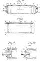
- FIGs 3 and 4 illustrate a vibration-damping arrangement according to the invention.
- the damping arrangement is shown mounted in the handle 2 to the right of Figure 1, which handle is made of a rigid material, such as steel for example.
- the arrangement comprises an external cylindrical grip 9 arranged to be grasped by the hand 10 of the operator.
- an elongate, airtight bladder 11 which is filled with gas, e.g. air, at a pressure above ambient or atmospheric pressure, suitable at a pressure exceeding 1 atm above the atmospheric or more.
- the magnitude of the gas pressure is dependent on the amplitude of the vibrations acting on the handle 2, and increases with increasing amplitude of oscillation.
- the bladder, or pressure chamber 9 is made from a material which is flexible but not stretchable, or which can only be stretched to a negligible extent, for example an airtight plastics material, a woven reinforced rubber material, or the like.
- the bladder 11 may be glued in a punctiform manner to the inside of the grip 9 or handle 2, or secured thereto in any other suitable manner. It is normally assumed, however, that the size of the bladder is such as to cause it to wedge firmly in between the sleeve 9 and the handle 2. It is essential that there is no direct mechanical contact between grip and handle which might be liable to transmit vibrations. When the handle 2 is subjected to radially acting vibrations or oscillations, the gas in the bladder 11 will be compressed and the gas pressure will rise proportionally to the magnitude of the vibrations. It is essential that the material from which the bladder 11 is made cannot be stretched, or can only be stretched to an insignificant degree, to enable the desired variations in compression to be obtained in response to vibrations from the handle. Tests have shown that an extraordinarily good vibration-inhibiting effect is obtained by means of the invention throughout the whole of the frequency range relevant to both slow and fast-operating machines.
- the end of the grip 9, shown to the right of Fig. 4 may be provided with a protective cap or a thin membrane.
- the pressure chamber of bladder 11 may suitably be provided with a valve through which air under pressure may be supplied to the bladder interior.
- Figure 5 illustrates a modified embodiment, in which two bladders, 12 and 13, are arranged between an external, slit grip 14 and an internal handle 15 which is connected to the machine and which has a rectangular cross-sectional shape.
- the bladders which have the form of elongate hoses, are fixedly glued to the handle 15.
- the bladders 12 and 13 are also anchored between the inner wall of the grip 14 and the outer surfaces of the handle 15, as a result of the pressure prevailing in the bladders.
- Fig. 6 is a radial sectional view of another embodiment, this embodiment having four bladders 16, 17, 18 and 19 tensioned between a grip 20 and a handle 21 connected to the tool.
- the illustrated grips 11, 14 and 20 have a cylindrical shape, it will be understood that the outer and inner surfaces thereof may have any suitable shape whatsoever.
- the pressure chambers or bladders 11, 12, 13, 16, 17, 18 and 19 preferably extend along the whole of the grip.
- Each bladder, for example the bladder 11, may be divided axially of the handle into a plurality of mutually adjacent bladders, or may comprise a plurality of spherical bladders packed between the grip and the handle.
- the sole function in practice of the described, preferably rigid grip, for example the grip 9, is to protect the bladder or bladders and to form a means which can be given an anatomically correct shape.
- the grip may be omitted and the bladder or bladders gripped directly.
- the requisite bladder working under a pressure above atmospheric or ambient pressure may have the form of a hose wound helically about the handle.
- FIGS 7-10 illustrate a further embodiment of the invention.
- This embodiment comprises a hollow body 22 of flexible and stretchable material, for instance a rubber material with tapered end sections 23 and 24 respectively, as well as a cylindrical section 25, affording the connection between said end sections 23 and 24.
- the ends of the cylindrical sections 25 are furnished with annular grooves 26 and 27 respectively, and the tapered end sections 23, 25 are provided with apertures 28 and 29 respectively, being centred in relation to the central axis 30 of the cylindrical section 25.
- Annular flanges 31 and 32 respectively for accommodation of a handle 33 (Fig. 9) are connected to the apertures 28 and 29.
- the flanges 31 and 32 are connected in an airtight manner with the handle 33, for instance by vulcanizing, gluing or some other suitable means.
- the material in the tapers 23 and 24 is made as thin as possible, and each taper may be provided on the outside or as shown on the inside with annular stiffening ribs, for example the stiffening ribs 34 and 35.
- the grip 36 is provided with 2 annular flanges 37 and 38 which, when the flexible hollow body 22 is inserted into the sleeve, snap into the grooves 26 and 27 respectively, causing the body 22 to be retained in an axially determined position relative to the sleeve 36.
- This position is evident from, for example, Fig. 9, which shows the left end of body 22, the sleeve 36 and the portion of the handle 32 which is connected in an airtight manner with the body 22.
- Fig. 7 shows the elastic hollow body 22 in the unloaded. state, i.e. when the inner pressure is equal to the outer pressure
- Fig. 9 shows the loaded state, i.e. when the airtight body 22 has an inner positive pressure exceeding ambient pressure by approx. 1 atmosphere or more.
- the central section 25 of the body 22 is firmly tensioned towards the inner surface 39 of the sleeve 36.
- the free portions of the body 22, i.e. the shown tapered end sections 23 and 24, have been stretched out, as is evident from Fig. 9.
- the inner pressure in the body 22 and the properties and dimensions of the material in the free end sections 23 and 24 have been so chosen that a further stretching of the end sections 23 and 24 requires a relatively large force, relative to that required to accomplish the initial stretching by means of the inner positive pressure.
- the inner positive pressure has accomplished a stretching which approaches the maximum stretch, with an adequate margin of safety to the rupture limit of the material.
- the material in the end sections 23 and 24 may be regarded as virtually unstretchable for transiently acting surge forces, i.e. it will be possible despite a non-reinforced elastic material having been chosen for the body 22 to bring about the requisite compression of the air or gas enclosed in the body 22.
- FIG. 10 shows the state of the arrangement illustrated in Fig. 9, when the handle 33 connected to the machine performs a downward stroke during the vibrations.
- the upper portion 23' of end section 23 will then be straightened out and consequently the total volume in the interior of the body 22 will be reduced in correspondence to the difference between the expanded state for the respective end section in Fig. 9 to the levelled-out state shown in Fig. 10.
- No corresponding stretching of the free end portion 23" lying under the handle 33 takes palce, since the flexible material is under great tension and the relief accomplished through the downward movement of the handle 33 is not so great as to permit any further stretching.
- the free end portions 23, 24 are conically shaped in the unloaded state, but naturally they may also be, for example, spherical and, furthermore, the sleeve 36 may have an essentially triangular or rectangular cross-sectional area.
- the apertures 28 and 29 must also be adapted to the cross-sectional area of the handle 33.
- the choice of material and the mode of loading the material according to the invention enable the walls of the gas-filled bodies to be made considerably thinner than is customary in conventional elastic bladders or bodies, and this in turn enables the vibration forces transmitted via the material to be kept at a minimum level.
Landscapes
- Engineering & Computer Science (AREA)
- Mechanical Engineering (AREA)
- General Engineering & Computer Science (AREA)
- Chemical & Material Sciences (AREA)
- Combustion & Propulsion (AREA)
- Transportation (AREA)
- Vibration Prevention Devices (AREA)
- Golf Clubs (AREA)
- Buildings Adapted To Withstand Abnormal External Influences (AREA)
- Vibration Dampers (AREA)
- Structures Of Non-Positive Displacement Pumps (AREA)
- Confectionery (AREA)
- Combined Devices Of Dampers And Springs (AREA)
- Motor Or Generator Frames (AREA)
- Percussive Tools And Related Accessories (AREA)
- Filling Or Discharging Of Gas Storage Vessels (AREA)
- Reciprocating, Oscillating Or Vibrating Motors (AREA)
Priority Applications (1)
| Application Number | Priority Date | Filing Date | Title |
|---|---|---|---|
| AT82850002T ATE16629T1 (de) | 1981-01-28 | 1982-01-08 | Schwingungsdaempfende vorrichtung. |
Applications Claiming Priority (2)
| Application Number | Priority Date | Filing Date | Title |
|---|---|---|---|
| SE8100532 | 1981-01-28 | ||
| SE8100532 | 1981-01-28 |
Publications (3)
| Publication Number | Publication Date |
|---|---|
| EP0057166A2 true EP0057166A2 (de) | 1982-08-04 |
| EP0057166A3 EP0057166A3 (en) | 1983-04-27 |
| EP0057166B1 EP0057166B1 (de) | 1985-11-21 |
Family
ID=20343002
Family Applications (1)
| Application Number | Title | Priority Date | Filing Date |
|---|---|---|---|
| EP82850002A Expired EP0057166B1 (de) | 1981-01-28 | 1982-01-08 | Schwingungsdämpfende Vorrichtung |
Country Status (10)
| Country | Link |
|---|---|
| US (1) | US4421181A (de) |
| EP (1) | EP0057166B1 (de) |
| JP (1) | JPS57173481A (de) |
| AT (1) | ATE16629T1 (de) |
| CA (1) | CA1185623A (de) |
| DE (1) | DE3267473D1 (de) |
| DK (1) | DK33182A (de) |
| ES (1) | ES263467Y (de) |
| NO (1) | NO149460C (de) |
| SE (1) | SE8107226L (de) |
Cited By (3)
| Publication number | Priority date | Publication date | Assignee | Title |
|---|---|---|---|---|
| GB2262467A (en) * | 1991-12-17 | 1993-06-23 | Ingersoll Rand Co | Apparatus for reducing vibration transmission in hand-held tool |
| EP0703320A3 (de) * | 1994-09-19 | 1996-10-16 | Diehl Remscheid Gmbh & Co | Führungsrahmen mit Handführung für Verdichter |
| DE19853640A1 (de) * | 1998-11-20 | 2000-06-08 | Molecular Machines & Ind Gmbh | Mehrgefäßanordnung mit verbesserter Empfindlichkeit für die optische Analytik |
Families Citing this family (15)
| Publication number | Priority date | Publication date | Assignee | Title |
|---|---|---|---|---|
| US4535649A (en) * | 1983-01-28 | 1985-08-20 | Drag Specialties, Inc. | Anti-slip handlebar grip |
| SE442963B (sv) * | 1984-05-07 | 1986-02-10 | Atlas Copco Ab | Vibrationsisolerande handtag |
| US5588903A (en) * | 1994-08-08 | 1996-12-31 | Indresco Inc. | Ergonomic power tool |
| DE19646622B4 (de) * | 1996-11-12 | 2004-07-01 | Wacker Construction Equipment Ag | An einem Handgriff führbares Arbeitsgerät |
| US6082468A (en) * | 1998-04-20 | 2000-07-04 | Snap-On Tools Company | Interchangeable grips for power hand tools |
| DE20016639U1 (de) | 2000-09-26 | 2001-02-08 | TRW Automotive Safety Systems GmbH & Co. KG, 63743 Aschaffenburg | Lenkrad |
| DE10055395A1 (de) * | 2000-11-09 | 2002-05-29 | Bosch Gmbh Robert | Handwerkzeugmaschinenhandgriff |
| DE10160864A1 (de) * | 2001-12-12 | 2003-06-26 | Hilti Ag | Axial schlagendes Elektrohandwerkzeuggerät |
| DE20211390U1 (de) * | 2002-07-10 | 2003-11-20 | Dolmar GmbH, 22045 Hamburg | Einstellbares Federungs-Dämpfungs-System (Antivibrationssystem), insbesondere für ein handgehaltenes Arbeitsgerät |
| DE10347944B4 (de) * | 2003-10-15 | 2016-11-10 | Robert Bosch Gmbh | Zusatzhandgriff |
| SE526406C2 (sv) * | 2004-01-14 | 2005-09-06 | Silvent Ab | Ljuddämpare för pneumatiska maskiner |
| GB2423495A (en) * | 2005-02-24 | 2006-08-30 | Black & Decker Inc | Vibration damping handle assembly for hammer |
| US20070261208A1 (en) * | 2006-05-15 | 2007-11-15 | Ishai Alon B | Cushioned handle |
| DE102007048887B4 (de) * | 2007-10-11 | 2017-10-26 | Andreas Stihl Ag & Co. Kg | Handgeführtes Arbeitsgerät |
| US8881347B2 (en) | 2012-08-24 | 2014-11-11 | Feinstein Patents Llc | Vibration and pressure damping device for gripping handles and steering mechanisms |
Family Cites Families (15)
| Publication number | Priority date | Publication date | Assignee | Title |
|---|---|---|---|---|
| DE55803C (de) * | H. WATER-SON in 67 Albert Road, Aston, England | Handgriff-Bekleidung für Fahrräder zum Abschwächen der Stöfse | ||
| DE288135C (de) * | 1915-04-19 | |||
| GB191513892A (en) * | 1916-03-30 | 1916-08-31 | Americ Edwin Flaxman | An Improved Handle or Grip for the Steering Wheels, Steering Levers or Handle Bars of Motor Cars, Cycles and other Vehicles. |
| US2101869A (en) * | 1934-11-27 | 1937-12-14 | Sullivan Machinery Co | Vibration reducing means |
| DE675170C (de) * | 1936-11-11 | 1939-05-02 | Karl Hagebeuker | Handgriff mit schraubenfoermig gewundenem Luftschlauch |
| DE709757C (de) * | 1939-12-08 | 1941-08-26 | Wilhelm Eifert | Ausbildung des Handgriffs an Druckluft- und Elektroschlagwerkzeugen |
| FR992920A (fr) * | 1944-09-30 | 1951-10-24 | Poignée pneumatique pour guidons de cycles et motocycles | |
| US2984210A (en) * | 1958-07-15 | 1961-05-16 | Thor Power Tool Co | Shock-absorbing handle structure for pneumatic tools |
| DE1628003A1 (de) * | 1966-12-10 | 1971-01-28 | Tornado Gmbh | Handgriff fuer Bolzengeraete oder aehnliche Werkzeuge und Geraete |
| US3713350A (en) * | 1971-05-17 | 1973-01-30 | Schwinn Bicycle Co | Air cushion handlebar grip |
| US3889763A (en) * | 1973-10-31 | 1975-06-17 | Skil Corp | Vibration isolation handle for portable chain saw or the like |
| US4044625A (en) * | 1976-07-01 | 1977-08-30 | Chicago Pneumatic Tool Company | Vibration isolating hand grip for shank of a percussive chisel |
| DE2743043C2 (de) * | 1977-09-24 | 1987-05-14 | Fa. Andreas Stihl, 7050 Waiblingen | Schwingungsdämpfende Verbindung zwischen einem schwingungsbeaufschlagten Geräteteil und einem griffseitigen Geräteteil für ein tragbares Arbeitsgerät |
| HU177946B (en) * | 1979-03-02 | 1982-02-28 | Banyaszati Aknamelyito | Vibration damper for damping unhaalthy vibrations in pneumatic way at precussion-rotary hand tools |
| FR2494367B1 (fr) * | 1980-11-17 | 1986-08-22 | Sardou Max | Ressorts composites a fibres et matrices |
-
1981
- 1981-12-03 SE SE8107226A patent/SE8107226L/ not_active Application Discontinuation
-
1982
- 1982-01-08 DE DE8282850002T patent/DE3267473D1/de not_active Expired
- 1982-01-08 AT AT82850002T patent/ATE16629T1/de active
- 1982-01-08 EP EP82850002A patent/EP0057166B1/de not_active Expired
- 1982-01-19 US US06/340,758 patent/US4421181A/en not_active Expired - Fee Related
- 1982-01-19 CA CA000394448A patent/CA1185623A/en not_active Expired
- 1982-01-22 JP JP57007748A patent/JPS57173481A/ja active Pending
- 1982-01-26 DK DK33182A patent/DK33182A/da not_active Application Discontinuation
- 1982-01-27 NO NO820241A patent/NO149460C/no unknown
- 1982-01-27 ES ES1982263467U patent/ES263467Y/es not_active Expired
Cited By (4)
| Publication number | Priority date | Publication date | Assignee | Title |
|---|---|---|---|---|
| GB2262467A (en) * | 1991-12-17 | 1993-06-23 | Ingersoll Rand Co | Apparatus for reducing vibration transmission in hand-held tool |
| EP0703320A3 (de) * | 1994-09-19 | 1996-10-16 | Diehl Remscheid Gmbh & Co | Führungsrahmen mit Handführung für Verdichter |
| DE19853640A1 (de) * | 1998-11-20 | 2000-06-08 | Molecular Machines & Ind Gmbh | Mehrgefäßanordnung mit verbesserter Empfindlichkeit für die optische Analytik |
| DE19853640C2 (de) * | 1998-11-20 | 2002-01-31 | Molecular Machines & Ind Gmbh | Mehrgefäßanordnung mit verbesserter Empfindlichkeit für die optische Analytik, Verfahren zu ihrer Herstellung sowie ihre Verwendung in optischen Analyseverfahren |
Also Published As
| Publication number | Publication date |
|---|---|
| JPS57173481A (en) | 1982-10-25 |
| EP0057166A3 (en) | 1983-04-27 |
| SE8107226L (sv) | 1982-07-29 |
| DE3267473D1 (en) | 1986-01-02 |
| ES263467Y (es) | 1983-03-01 |
| ES263467U (es) | 1982-07-16 |
| DK33182A (da) | 1982-07-29 |
| NO149460B (no) | 1984-01-16 |
| NO149460C (no) | 1984-05-02 |
| CA1185623A (en) | 1985-04-16 |
| NO820241L (no) | 1982-07-29 |
| US4421181A (en) | 1983-12-20 |
| EP0057166B1 (de) | 1985-11-21 |
| ATE16629T1 (de) | 1985-12-15 |
Similar Documents
| Publication | Publication Date | Title |
|---|---|---|
| US4421181A (en) | Vibration-damping arrangement | |
| US4800965A (en) | Damping element, and its installation in a motor-driven hand tool | |
| US4757982A (en) | Engine mount with hydraulic damping | |
| EP0172700B1 (de) | Hydraulisch gedämpftes Lager | |
| US6007439A (en) | Vibration dampener for metal ball bats and similar impact implements | |
| EP2109519B1 (de) | Stossdämpfung für ein elektrowerkzeug | |
| JP4855646B2 (ja) | 非空気圧タイヤ | |
| US5024425A (en) | Elastomeric sleeve spring | |
| EP1511951B1 (de) | Luftfeder mit schwingungsisolierung | |
| US6994068B2 (en) | Antivibration device | |
| RU2458774C2 (ru) | Ручная шлифовальная машина | |
| US4609055A (en) | Vibrating plate | |
| EP0457740A1 (de) | Handgeführte rotierende Schleifmaschine mit Schwingungsdämpfung | |
| GB2138348A (en) | Vibration damping handgrip | |
| Andersson | Design and testing of a vibration attenuating handle | |
| US12109673B1 (en) | Vibration suppression bar handle structures for high-vibration handheld machines | |
| USRE23437E (en) | Oleopneumatic device | |
| EP0081079B1 (de) | Einrichtung zur Dämpfung der Schwingungsübertragung | |
| GB1583185A (en) | Tyre and wheel rim assembly incorporating an elastically deformable structure | |
| SU368019A1 (ru) | Ручной инструмент ударного действия | |
| RU2001738C1 (ru) | Виброзащитна муфта дл ударного инструмента | |
| RU2237205C1 (ru) | Амортизатор | |
| JP2024534718A (ja) | 衝撃吸収のための装置、システム、および方法 | |
| RU40986U1 (ru) | Виброизолирующая рукоятка | |
| GB2180318A (en) | Vehicle suspension system |
Legal Events
| Date | Code | Title | Description |
|---|---|---|---|
| PUAI | Public reference made under article 153(3) epc to a published international application that has entered the european phase |
Free format text: ORIGINAL CODE: 0009012 |
|
| AK | Designated contracting states |
Designated state(s): AT CH DE FR GB IT |
|
| PUAL | Search report despatched |
Free format text: ORIGINAL CODE: 0009013 |
|
| AK | Designated contracting states |
Designated state(s): AT CH DE FR GB IT LI |
|
| 17P | Request for examination filed |
Effective date: 19830323 |
|
| RAP1 | Party data changed (applicant data changed or rights of an application transferred) |
Owner name: BYGGERGONOMILABORATORIET HB |
|
| GRAA | (expected) grant |
Free format text: ORIGINAL CODE: 0009210 |
|
| AK | Designated contracting states |
Designated state(s): AT CH DE FR GB IT LI |
|
| REF | Corresponds to: |
Ref document number: 16629 Country of ref document: AT Date of ref document: 19851215 Kind code of ref document: T |
|
| ITF | It: translation for a ep patent filed | ||
| ET | Fr: translation filed | ||
| REF | Corresponds to: |
Ref document number: 3267473 Country of ref document: DE Date of ref document: 19860102 |
|
| PG25 | Lapsed in a contracting state [announced via postgrant information from national office to epo] |
Ref country code: AT Effective date: 19860108 |
|
| PG25 | Lapsed in a contracting state [announced via postgrant information from national office to epo] |
Ref country code: LI Effective date: 19860131 Ref country code: CH Effective date: 19860131 |
|
| PLBE | No opposition filed within time limit |
Free format text: ORIGINAL CODE: 0009261 |
|
| STAA | Information on the status of an ep patent application or granted ep patent |
Free format text: STATUS: NO OPPOSITION FILED WITHIN TIME LIMIT |
|
| PG25 | Lapsed in a contracting state [announced via postgrant information from national office to epo] |
Ref country code: FR Free format text: LAPSE BECAUSE OF NON-PAYMENT OF DUE FEES Effective date: 19860930 |
|
| REG | Reference to a national code |
Ref country code: CH Ref legal event code: PL |
|
| 26N | No opposition filed | ||
| REG | Reference to a national code |
Ref country code: FR Ref legal event code: ST |
|
| GBPC | Gb: european patent ceased through non-payment of renewal fee | ||
| PG25 | Lapsed in a contracting state [announced via postgrant information from national office to epo] |
Ref country code: DE Effective date: 19871001 |
|
| PG25 | Lapsed in a contracting state [announced via postgrant information from national office to epo] |
Ref country code: GB Effective date: 19881121 |
|
| PGFP | Annual fee paid to national office [announced via postgrant information from national office to epo] |
Ref country code: LU Payment date: 19931201 Year of fee payment: 14 |
|
| EPTA | Lu: last paid annual fee |