EP0056847A2 - Device for removing and stowing a spare wheel stored under the tilting body of a tipper-lorry - Google Patents
Device for removing and stowing a spare wheel stored under the tilting body of a tipper-lorry Download PDFInfo
- Publication number
- EP0056847A2 EP0056847A2 EP81108963A EP81108963A EP0056847A2 EP 0056847 A2 EP0056847 A2 EP 0056847A2 EP 81108963 A EP81108963 A EP 81108963A EP 81108963 A EP81108963 A EP 81108963A EP 0056847 A2 EP0056847 A2 EP 0056847A2
- Authority
- EP
- European Patent Office
- Prior art keywords
- lever arm
- spare wheel
- vehicle
- rotary bearing
- bridge
- Prior art date
- Legal status (The legal status is an assumption and is not a legal conclusion. Google has not performed a legal analysis and makes no representation as to the accuracy of the status listed.)
- Granted
Links
- 230000003028 elevating effect Effects 0.000 abstract 1
- 238000010276 construction Methods 0.000 description 2
- 208000027418 Wounds and injury Diseases 0.000 description 1
- 230000006378 damage Effects 0.000 description 1
- 230000008030 elimination Effects 0.000 description 1
- 238000003379 elimination reaction Methods 0.000 description 1
- 230000002349 favourable effect Effects 0.000 description 1
- 208000014674 injury Diseases 0.000 description 1
- 238000003780 insertion Methods 0.000 description 1
- 230000037431 insertion Effects 0.000 description 1
- 239000000725 suspension Substances 0.000 description 1
Images
Classifications
-
- B—PERFORMING OPERATIONS; TRANSPORTING
- B62—LAND VEHICLES FOR TRAVELLING OTHERWISE THAN ON RAILS
- B62D—MOTOR VEHICLES; TRAILERS
- B62D43/00—Spare wheel stowing, holding, or mounting arrangements
- B62D43/02—Spare wheel stowing, holding, or mounting arrangements external to the vehicle body
- B62D43/04—Spare wheel stowing, holding, or mounting arrangements external to the vehicle body attached beneath the vehicle body
- B62D43/045—Spare wheel stowing, holding, or mounting arrangements external to the vehicle body attached beneath the vehicle body the wheel or its cradle being attached to one or more chains or cables for handling
Definitions
- the invention relates to a device for removing and inserting a spare wheel, which is accommodated under tipping trucks in tippers on truck vehicles, essentially consisting of a lever arm which is rotatably mounted on one side of the vehicle and at the other end a rope run for a rope winch provided lifting device.
- an angular lever arm has at one end a pivot pin which can be inserted from above into a sleeve formed on the subframe or chassis of the vehicle, and at its other end a cantilever arm ; this boom is slidably disposed with respect to the lever arm or is pivotably attached to the lever arm.
- the largest dimensions of the device when the boom is retracted or swung in are smaller than the dimensions of the cavity enclosed by the spare wheel. Accordingly, the device can be removed from the subframe / chassis and housed in the interior of the spare wheel; in practice, a plastic bag is used to protect the device.
- the invention is therefore based on the object of eliminating the disadvantages of the known device, in particular thus creating a device which is safer in terms of accident, requires a minimum of operating effort and satisfies the stated regulations.
- the vehicle-side rotary bearing of the one-piece lever arm is attached to the tilting bridge and is arranged such that when the tilting bridge is raised to remove / insert the spare wheel, the axis of rotation of the rotary bearing is at right angles to the vehicle.
- a structure of the invention that is simple in terms of weight, and particularly favorable in tight spaces, is that the vehicle-side pivot bearing is formed from a pivot pin arranged on the tilting bridge and a socket held on the pivot pin, which with the lever arm provides space for one Removing / inserting the spare wheel enlarging angle is connected.
- the socket on the pivot pin can be used for good accessibility when mounting and removing the device on the pivot pin on the pivot bridge side are held in that a respective shoulder of two half-shells detachably connected to the pivot of the pivot bearing engages in a circumferential groove let into the bushing of the pivot bearing from the outside.
- a last embodiment of the invention provides that a rigid support connected to the bushing and to the lever arm is attached below the connection point between the bushing of the rotary bearing and the lever arm, which at the same time a receptacle for a rotatably mounted rope pulley and a lifting device interacting with it, for example forms a manually operated safety ratchet winch, with the support and the lever arm having passage openings for a rope of the lifting device.
- the advantages that can be achieved with the object according to the invention are, in particular, that the device is ready for use after the removal and insertion of the spare wheel accommodated under the tipping bridge, without any dangerous actions for the driving personnel, and is particularly continuously available.
- the arrangement according to the invention of the axis of the rotary bearing when the tilting bridge is raised advantageously results in positions of the lever arm that are free of restoring forces and thus can only be changed intentionally.
- the simple construction, in particular the one-piece design of the lever arm and the associated elimination of the previously known telescopic / pivotable arm make the device cheaper, easier to operate and maintain.
- a spare wheel 4 is located under a tilting bridge 3 in the center of the vehicle on an auxiliary or intermediate space 8 articulated on the chassis.
- a pivot pin la of a rotary bearing 1 is fastened, which is shown in more detail in FIG . 1, 2 and 4, the rotary bearing 1 also has a bushing lb which, on the one hand, engages around the pivot pin la and, on the other hand, is connected to a one-piece lever arm 2 designed as a hollow body.
- the other end of the lever arm 2 is provided with a rope guide 7b for a rope 7c of a lifting device 7, according to FIG. 4 a safety ratchet winch.
- the end of the cable 7c pointing towards the spare wheel 4 can be connected to the spare wheel 4 via hooks 7d located thereon.
- the other end of the rope 7c is guided via a deflection arranged within the lever arm 2, according to FIG. 4 via a bolt 2a welded into the lever arm 2, and via visible through openings in the lever arm 2 and in a support 6 on a rope pulley 7a arranged therein.
- the support 6 lies below the connection point between the bushing lb and the lever arm 2, is welded to these two parts, serves for bracing this connection point and, in addition to the already mentioned mounting of the rope sheave 7a, also for attaching the lifting device 7.
- the bush 1b also has a circumferential groove 1c, into which lugs 5a of two half-shells 5 engage; these half-shells 5 envelop the upper, offset part of the pivot pin la and are connected to it together via a screw connection.
- the hooks 7d are fixed to a suspension 3a attached to the tilting bridge 3.
Landscapes
- Engineering & Computer Science (AREA)
- Chemical & Material Sciences (AREA)
- Combustion & Propulsion (AREA)
- Transportation (AREA)
- Mechanical Engineering (AREA)
- Jib Cranes (AREA)
- Vehicle Cleaning, Maintenance, Repair, Refitting, And Outriggers (AREA)
- Emergency Lowering Means (AREA)
- Lift-Guide Devices, And Elevator Ropes And Cables (AREA)
Abstract
Description
Die Erfindung betrifft eine Vorrichtung zum Entnehmen und Einbringen eines'bei Kippern aufLKW-Fahrzeugen unter der Kippbrücke untergebrachten Reserverades, im wesentlichen bestehend aus einem Hebelarm, der an dem einen Ende fahrzeugseitig drehbar gelagert ist und an dem anderen Ende eine Seillaufführung für eine mit einer Seilwinde versehene Hubvorrichtung aufweist.The invention relates to a device for removing and inserting a spare wheel, which is accommodated under tipping trucks in tippers on truck vehicles, essentially consisting of a lever arm which is rotatably mounted on one side of the vehicle and at the other end a rope run for a rope winch provided lifting device.
Bei einer nach der DE-PS 19 14 591 bekannten Vorrichtung der gattungsgemäßen Art weist ein winkeliger Hebelarm an seinem einen Ende einen von oben in eine am Hilfsrahmen oder Fahrgestell des Fahrzeuges ausgebildete Hülse einsteckbaren Drehzapfen und an seinem anderen Ende einen mit einer Seillaufführung versehenen Ausleger auf; dieser Ausleger ist gegenüber dem Hebelarm verschiebbar angeordnet oder an dem Hebelarm verschwenkbar befestigt. Außerdem sind die größten Abmessungen der Vorrichtung bei eingezogenem oder eingeschwenktem Ausleger kleiner als die Abmessungen des von dem Reserverad umschlossenen Hohlraumes. Demnach kann die Vorrichtung vom Hilfsrahmen/ Fahrgestell abgenommen und im Innenraum des Reserverades untergebracht werden; in der Praxis wird dabei ein Kunststoffsack zum Schutz der Vorrichtung angewandt. Wenngleich mit dieser Vorrichtung im wesentlichen eine praktische Ausnutzung des sonst auch beispielsweise zum Unberbringen von Schneeketten genutzten Innenraumes eines Reserverades gegeben ist, so liegt doch nachteilig die Gefahr von Personenschäden infolge der notwendigen manuellen Verrichtungen beim Verschieben/Verschwenken des Auslegers sowie beim Einstecken und Herausheben der nach ihrem Aufbau recht schweren Vorrichtung aus der fahrzeugseitigen Hülse vor. Überdies besteht die Möglichkeit, daß die Fahrzeuge im Betrieb nicht mit dieser Vorrichtung ausgerüstet sind, was gegen einschlägige Vorschriften der Straßenverkehrs-Zulassungs-Ordnung verstoßen würde.In a device of the generic type known from DE-PS 19 14 591, an angular lever arm has at one end a pivot pin which can be inserted from above into a sleeve formed on the subframe or chassis of the vehicle, and at its other end a cantilever arm ; this boom is slidably disposed with respect to the lever arm or is pivotably attached to the lever arm. In addition, the largest dimensions of the device when the boom is retracted or swung in are smaller than the dimensions of the cavity enclosed by the spare wheel. Accordingly, the device can be removed from the subframe / chassis and housed in the interior of the spare wheel; in practice, a plastic bag is used to protect the device. If with this device, there is essentially a practical use of the interior of a spare wheel, which is otherwise also used, for example, for storing snow chains, but there is disadvantageously the risk of personal injury as a result of the necessary manual operations when moving / pivoting the boom and when inserting and removing the their construction quite heavy device from the vehicle-side sleeve. In addition, there is the possibility that the vehicles are not equipped with this device during operation, which would violate the relevant regulations of the traffic regulations.
Der Erfindung liegt demnach die Aufgabe zugrunde, die zu der bekannten Vorrichtung aufgezeigten Nachteile aufzuheben, insbesondere also eine Vorrichtung zu schaffen, die unfallsicherer ist, ein Minimum an Bedienungsaufwand erfordert und den angeführten Vorschriften genügt.The invention is therefore based on the object of eliminating the disadvantages of the known device, in particular thus creating a device which is safer in terms of accident, requires a minimum of operating effort and satisfies the stated regulations.
Diese Aufgabe wird erfindungsgemäß dadurch gelöst, daß die fahrzeugseitige Drehlagerung des einteilig ausgebildeten Hebelarmes an der Kippbrücke befestigt und derart angeordnet ist, daß bei zum Entnehmen/Einbringen des Reserverades angehobener Kippbrücke die Drehachse der Drehlagerung rechtwinklig zum Fahrzeug steht.This object is achieved in that the vehicle-side rotary bearing of the one-piece lever arm is attached to the tilting bridge and is arranged such that when the tilting bridge is raised to remove / insert the spare wheel, the axis of rotation of the rotary bearing is at right angles to the vehicle.
Eine in ihrem Aufbau einfache, gewichtlich und insbesondere bei beengten Raumverhältnissen günstige Ausgestaltung nach der Erfindung besteht darin, daß die fahrzeugseitige Drehlagerung aus einem an der Kippbrücke angeordneten Drehzapfen und einer an dem Drehzapfen gehalterten Buchse gebildet ist, die mit dem Hebelarm unter einem die Raumfreiheit zum Entnehmen/Einbringen des Reserverades vergrößernden Winkel verbunden ist.A structure of the invention that is simple in terms of weight, and particularly favorable in tight spaces, is that the vehicle-side pivot bearing is formed from a pivot pin arranged on the tilting bridge and a socket held on the pivot pin, which with the lever arm provides space for one Removing / inserting the spare wheel enlarging angle is connected.
Für eine gute Zugänglichkeit beim An- und Abbau der Vorrichtung an dem kippbrückenseitigen Drehzapfen kann die Buchse an dem Drehzapfen in Weiterbildung der Erfindung dadurch gehaltert werden, daß in eine von außen in die Buchse der Drehlagerung eingelassene Umfangsnut ein jeweiliger Ansatz von zwei mit dem Drehzapfen der Drehlagerung lösbar verbundenen Halbschalen eingreift.In a further development of the invention, the socket on the pivot pin can be used for good accessibility when mounting and removing the device on the pivot pin on the pivot bridge side are held in that a respective shoulder of two half-shells detachably connected to the pivot of the pivot bearing engages in a circumferential groove let into the bushing of the pivot bearing from the outside.
Im Sinne einer stabilen und dennoch leichten Ausbildung der Vorrichtung sowie ihrer kompakten Bauweise sieht eine letzte Ausgestaltung der Erfindung vor, daß unterhalb der Verbindungsstelle zwischen der Buchse der-Drehlagerung und dem Hebelarm eine an der Buchse und an dem Hebelarm angeschlossene, biegesteife Abstützung angebracht ist, die gleichzeitig eine Aufnahme für eine drehbar gelagerte Seilscheibe und eine damit zusammenwirkende Hubvorrichtung, z.B. eine von Hand betätigbare Sicherheitsratschen-Seilwinde, bildet, wobei die Abstützung und der Hebelarm Durchtrittsöffnungen für ein Seil der Hubvorrichtung aufweisen.In the sense of a stable, yet light design of the device and its compact design, a last embodiment of the invention provides that a rigid support connected to the bushing and to the lever arm is attached below the connection point between the bushing of the rotary bearing and the lever arm, which at the same time a receptacle for a rotatably mounted rope pulley and a lifting device interacting with it, for example forms a manually operated safety ratchet winch, with the support and the lever arm having passage openings for a rope of the lifting device.
Die mit dem Gegenstand nach der Erfindung erzielbaren Vorteile bestehen insbesondere darin, daß die Vorrichtung nach dem zum Entnehmen und Einbringen des unter der Kippbrücke untergebrachten Reserverades erfolgten Anheben der Kippbrücke ohne verletzungsgefährliche Handlungen für das Fahrpersonal einsatzbereit und ganz besonders auch ständig verfügbar ist. Im weiteren ergeben sich durch die erfindungsgemäße Anordnung der Achse der Drehlagerung bei angehobener Kippbrücke vorteilhaft von Rückstellkräften freie und damit nur gewollt veränderbare Stellungen des Hebelarmes. Außerdem sind durch den einfachen Aufbau, insbesondere durch die einteilige Ausbildung des Hebelarmes und des damit verbundenen Wegfalls des vorbekannten teleskopierbaren/verschwenkbaren Auslegers Herstellung, Bedienung und Wartung der Vorrichtung verbilligt bzw. vereinfacht.The advantages that can be achieved with the object according to the invention are, in particular, that the device is ready for use after the removal and insertion of the spare wheel accommodated under the tipping bridge, without any dangerous actions for the driving personnel, and is particularly continuously available. Furthermore, the arrangement according to the invention of the axis of the rotary bearing when the tilting bridge is raised advantageously results in positions of the lever arm that are free of restoring forces and thus can only be changed intentionally. In addition, the simple construction, in particular the one-piece design of the lever arm and the associated elimination of the previously known telescopic / pivotable arm, make the device cheaper, easier to operate and maintain.
Ein Ausführungsbeispiel der Erfindung ist in der Zeichnung dargestellt und wird nachfolgend näher beschrieben.
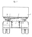
- Fig. 1 ein LKW-Fahrzeug im Querschnitt, mit horizontaler Kippbrücke und einer an dieser Brücke befestigten Vorrichtung zum Entnehmen und Einbringen eines Reserverades,
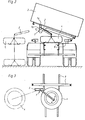
- Fig. 2 das LKW-Fahrzeug nach Fig. 1 mit angehobener Kippbrücke, dabei ausgeschwenktes Reserverad gestrichelt,
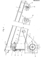
- Fig. 3 die Teildraufsicht zu Fig. 2, unter Fortlassung der Kippbrücke,
- Fig. 4 die Vorrichtung und deren
kippbrückenseitige Drehlagerung 1, im vergrößerten Maßstab und teilweise geschnitten.
- 1 shows a truck vehicle in cross section, with a horizontal tipping bridge and a device for removing and inserting a spare wheel attached to this bridge,
- 2 shows the truck vehicle according to FIG. 1 with the tipping bridge raised, the spare wheel swung out in dashed lines,
- 3 shows the partial top view of FIG. 2, omitting the tipping bridge,
- Fig. 4 shows the device and its tilting-side pivot bearing 1, on an enlarged scale and partially cut.
Nach den Fig. 1 bis 3 liegt unter einer Kippbrücke 3 in Fahrzeugquermitte ein Reserverad 4 auf einem am Fahrgestell angelenkten Hilfs- oder Zwischenraum 8. Am Boden der Kippbrücke 3 ist ein Drehzapfen la einer Drehlagerung 1 befestigt, die ausführlicher in Fig. 4 dargestellt ist. Weiter nach Fig. 1, 2 und 4 weist die Drehlagerung 1 noch eine Buchse lb auf, die einerseits den Drehzapfen la umgreift und andererseits mit einem als Hohlkörper ausgebildeten, einteiligen Hebelarm 2 verbunden ist. Das andere Ende des Hebelarmes 2 ist mit einer Seillaufführung 7b für ein Seil 7c einer Hubvorrichtung 7, nach Fig. 4 eine Sicherheitsratschen-Seilwinde, versehen. Das zum Reserverad 4 hin weisende Ende des Seiles 7c ist über daran befindliche Haken 7d mit dem Reserverad 4 verbindbar. Das andere Ende des Seiles 7c ist über eine innerhalb des Hebelarmes 2 angeordnete Umlenkung, nach Fig. 4 über einen im Hebelarm 2 eingeschweißten Bolzen 2a, und über ersichtliche Durchtrittsöffnungen in dem Hebelarm 2 sowie in einer Abstützung 6 auf eine darin angeordnete Seilscheibe 7a geführt. Die Abstützung 6 liegt unterhalb der Verbindungsstelle zwischen der Buchse lb und dem Hebelarm 2, ist mit diesen beiden Teilen verschweißt, dient zum Absteifen dieser Verbindungsstelle und, außer zur schon erwähnten Aufnahme der Seilscheibe 7a, noch zum Anbringen der Hubvorrichtung 7.According to FIGS. 1 to 3, a
Die Drehlagerung 1 ist gemäß Fig. 1 unter einem derartigen Winkel mit der Kippbrücke 3 befestigt, daß ihre Drehachse - wie die Fig. 2 und 4 zeigen - bei angehobener Kippbrücke 3 senkrecht zum Fahrzeug steht, so daß bei angehobener Kippbrücke 3 keine Rückstellkräfte vorliegen, die Stellung des Hebelarmes 2 also nur gewollt veränderbar ist. Aus den Fig. 1, 2 und.4 wird noch ersichtlich, daß der Hebelarm 2 mit der Buchse lb der Drehlagerung 1 unter einem die Raumfreiheit zum Entnehmen und Einbringen des Reserverades 4 vergrößernden Winkel verbunden ist.1 is attached to the
Nach Fig. 4 weist die Buchse lb noch eine Umfangsnut lc auf, in die Ansätze 5a von zwei Halbschalen 5 eingreifen; diese Halbschalen 5 umhüllen den oberen, abgesetzten Teil des Drehzapfens la und sind an diesem gemeinsam über eine Schraubverbindung angeschlossen. Bei Nichtgebrauch der Vorrichtung werden die Haken 7d an einer an der Kippbrücke 3 befestigten Aufhängung 3a festgelegt.According to FIG. 4, the
Claims (4)
Priority Applications (1)
| Application Number | Priority Date | Filing Date | Title |
|---|---|---|---|
| AT81108963T ATE14701T1 (en) | 1981-01-23 | 1981-10-27 | DEVICE FOR REMOVING AND INSERTING A SPARE WHEEL LOCATED UNDER THE TIPPER ON TRUCK VEHICLES. |
Applications Claiming Priority (2)
| Application Number | Priority Date | Filing Date | Title |
|---|---|---|---|
| DE3102205 | 1981-01-23 | ||
| DE19813102205 DE3102205A1 (en) | 1981-01-23 | 1981-01-23 | DEVICE FOR REMOVING AND PUTTING IN A RESERVER WHEEL UNDER THE TIPPER BRIDGE IN TIPPERS ON TRUCK VEHICLES |
Publications (3)
| Publication Number | Publication Date |
|---|---|
| EP0056847A2 true EP0056847A2 (en) | 1982-08-04 |
| EP0056847A3 EP0056847A3 (en) | 1983-06-15 |
| EP0056847B1 EP0056847B1 (en) | 1985-08-07 |
Family
ID=6123220
Family Applications (1)
| Application Number | Title | Priority Date | Filing Date |
|---|---|---|---|
| EP81108963A Expired EP0056847B1 (en) | 1981-01-23 | 1981-10-27 | Device for removing and stowing a spare wheel stored under the tilting body of a tipper-lorry |
Country Status (4)
| Country | Link |
|---|---|
| EP (1) | EP0056847B1 (en) |
| JP (1) | JPS57140283A (en) |
| AT (1) | ATE14701T1 (en) |
| DE (2) | DE3102205A1 (en) |
Cited By (2)
| Publication number | Priority date | Publication date | Assignee | Title |
|---|---|---|---|---|
| US5519423A (en) * | 1994-07-08 | 1996-05-21 | Hewlett-Packard Company | Tuned entrance fang configuration for ink-jet printers |
| GB2523470A (en) * | 2015-02-06 | 2015-08-26 | Daimler Ag | Mounting device for mounting a spare wheel on a structure of a vehicle |
Families Citing this family (2)
| Publication number | Priority date | Publication date | Assignee | Title |
|---|---|---|---|---|
| DE20008071U1 (en) * | 2000-05-04 | 2001-09-13 | Meiller Fahrzeuge | Vehicle body, in particular tipping bridge substructure, and associated floor panel |
| EP4257461A1 (en) * | 2022-04-07 | 2023-10-11 | Iveco S.P.A. | Moving of a load of a cargo vehicle |
-
1981
- 1981-01-23 DE DE19813102205 patent/DE3102205A1/en not_active Withdrawn
- 1981-10-27 AT AT81108963T patent/ATE14701T1/en not_active IP Right Cessation
- 1981-10-27 EP EP81108963A patent/EP0056847B1/en not_active Expired
- 1981-10-27 DE DE8181108963T patent/DE3171724D1/en not_active Expired
-
1982
- 1982-01-20 JP JP57006213A patent/JPS57140283A/en active Pending
Cited By (2)
| Publication number | Priority date | Publication date | Assignee | Title |
|---|---|---|---|---|
| US5519423A (en) * | 1994-07-08 | 1996-05-21 | Hewlett-Packard Company | Tuned entrance fang configuration for ink-jet printers |
| GB2523470A (en) * | 2015-02-06 | 2015-08-26 | Daimler Ag | Mounting device for mounting a spare wheel on a structure of a vehicle |
Also Published As
| Publication number | Publication date |
|---|---|
| ATE14701T1 (en) | 1985-08-15 |
| DE3102205A1 (en) | 1982-08-19 |
| EP0056847B1 (en) | 1985-08-07 |
| DE3171724D1 (en) | 1985-09-12 |
| JPS57140283A (en) | 1982-08-30 |
| EP0056847A3 (en) | 1983-06-15 |
Similar Documents
| Publication | Publication Date | Title |
|---|---|---|
| DE602004002468T2 (en) | ROTATABLE AND ROLLING MATERIAL HANDLING DEVICE | |
| DE2821295A1 (en) | CONTAINER LOADING DEVICE | |
| EP1396466B1 (en) | Industrial truck with a lateral opening for the removal of the batteries | |
| DE2702403A1 (en) | WINDSHIELD WIPERS | |
| EP0056847B1 (en) | Device for removing and stowing a spare wheel stored under the tilting body of a tipper-lorry | |
| DE2850667A1 (en) | SAFETY DEVICE FOR A LIFTING ARM | |
| DE4430573A1 (en) | Device for transporting silos | |
| EP0543276A1 (en) | Mobile crane | |
| DE3808313C2 (en) | ||
| DE3106117A1 (en) | "REAR DOOR FOR ARMORED VEHICLES" | |
| DE19840151B4 (en) | Support structure for wheeled vehicles | |
| DE8101660U1 (en) | DEVICE FOR REMOVING AND PUTTING IN A RESERVER WHEEL UNDER THE TIPPER BRIDGE IN TIPPERS ON TRUCK VEHICLES | |
| DE2406610C2 (en) | Turntable steering axle for a lift truck with hydraulic steering drive | |
| DE19721333C1 (en) | Rear portal support combination for vehicles of all kinds with a movable roof | |
| DE2743373C3 (en) | Electric carts with loading platform and hydraulic slewing crane located behind the driver's seat | |
| DE2944395C2 (en) | Gripping and loading device | |
| DE943457C (en) | Mobile concrete mixer or similar machine | |
| DE3239854C2 (en) | Crane carriage | |
| DE3215476A1 (en) | Roof rack for motor vehicles | |
| DE1229263B (en) | Truck with loading crane | |
| EP0316503B1 (en) | Lifting and pivoting device for the loading platforms of motor lorries | |
| DE2922995C2 (en) | Tilting device for the tiltable hanging of transport containers on lifting beams | |
| DE3440280A1 (en) | Device for changing the installation position of a fifth-wheel kingpin | |
| EP3960595A1 (en) | Trailer | |
| DE1161515B (en) | Overpass bridge |
Legal Events
| Date | Code | Title | Description |
|---|---|---|---|
| PUAI | Public reference made under article 153(3) epc to a published international application that has entered the european phase |
Free format text: ORIGINAL CODE: 0009012 |
|
| 17P | Request for examination filed |
Effective date: 19811027 |
|
| AK | Designated contracting states |
Designated state(s): AT BE CH DE FR GB IT LU NL SE |
|
| PUAL | Search report despatched |
Free format text: ORIGINAL CODE: 0009013 |
|
| AK | Designated contracting states |
Designated state(s): AT BE CH DE FR GB IT LI LU NL SE |
|
| ITF | It: translation for a ep patent filed |
Owner name: SOCIETA' ITALIANA BREVETTI S.P.A. |
|
| GRAA | (expected) grant |
Free format text: ORIGINAL CODE: 0009210 |
|
| AK | Designated contracting states |
Designated state(s): AT BE CH DE FR GB IT LI LU NL SE |
|
| REF | Corresponds to: |
Ref document number: 14701 Country of ref document: AT Date of ref document: 19850815 Kind code of ref document: T |
|
| REF | Corresponds to: |
Ref document number: 3171724 Country of ref document: DE Date of ref document: 19850912 |
|
| ET | Fr: translation filed | ||
| PGFP | Annual fee paid to national office [announced via postgrant information from national office to epo] |
Ref country code: AT Payment date: 19851030 Year of fee payment: 5 |
|
| PG25 | Lapsed in a contracting state [announced via postgrant information from national office to epo] |
Ref country code: LU Free format text: LAPSE BECAUSE OF NON-PAYMENT OF DUE FEES Effective date: 19851031 |
|
| PGFP | Annual fee paid to national office [announced via postgrant information from national office to epo] |
Ref country code: NL Payment date: 19851031 Year of fee payment: 5 |
|
| PLBE | No opposition filed within time limit |
Free format text: ORIGINAL CODE: 0009261 |
|
| STAA | Information on the status of an ep patent application or granted ep patent |
Free format text: STATUS: NO OPPOSITION FILED WITHIN TIME LIMIT |
|
| 26N | No opposition filed | ||
| PG25 | Lapsed in a contracting state [announced via postgrant information from national office to epo] |
Ref country code: AT Effective date: 19861027 |
|
| PG25 | Lapsed in a contracting state [announced via postgrant information from national office to epo] |
Ref country code: SE Effective date: 19861028 |
|
| PG25 | Lapsed in a contracting state [announced via postgrant information from national office to epo] |
Ref country code: LI Effective date: 19861031 Ref country code: CH Effective date: 19861031 Ref country code: BE Effective date: 19861031 |
|
| BERE | Be: lapsed |
Owner name: RINGFEDER G.M.B.H. Effective date: 19861031 |
|
| PG25 | Lapsed in a contracting state [announced via postgrant information from national office to epo] |
Ref country code: NL Effective date: 19870501 |
|
| NLV4 | Nl: lapsed or anulled due to non-payment of the annual fee | ||
| PG25 | Lapsed in a contracting state [announced via postgrant information from national office to epo] |
Ref country code: FR Free format text: LAPSE BECAUSE OF NON-PAYMENT OF DUE FEES Effective date: 19870630 |
|
| REG | Reference to a national code |
Ref country code: CH Ref legal event code: PL |
|
| GBPC | Gb: european patent ceased through non-payment of renewal fee | ||
| PG25 | Lapsed in a contracting state [announced via postgrant information from national office to epo] |
Ref country code: DE Effective date: 19870701 |
|
| REG | Reference to a national code |
Ref country code: FR Ref legal event code: ST |
|
| PG25 | Lapsed in a contracting state [announced via postgrant information from national office to epo] |
Ref country code: GB Effective date: 19881121 |
|
| EUG | Se: european patent has lapsed |
Ref document number: 81108963.0 Effective date: 19870812 |