EP0054973B1 - Device for producing rolls of flexible sheets wound in staggered overlapping formation - Google Patents
Device for producing rolls of flexible sheets wound in staggered overlapping formation Download PDFInfo
- Publication number
- EP0054973B1 EP0054973B1 EP81110742A EP81110742A EP0054973B1 EP 0054973 B1 EP0054973 B1 EP 0054973B1 EP 81110742 A EP81110742 A EP 81110742A EP 81110742 A EP81110742 A EP 81110742A EP 0054973 B1 EP0054973 B1 EP 0054973B1
- Authority
- EP
- European Patent Office
- Prior art keywords
- roll
- reel hub
- shingled
- pivoted
- strip
- Prior art date
- Legal status (The legal status is an assumption and is not a legal conclusion. Google has not performed a legal analysis and makes no representation as to the accuracy of the status listed.)
- Expired
Links
Images

Classifications
-
- B—PERFORMING OPERATIONS; TRANSPORTING
- B65—CONVEYING; PACKING; STORING; HANDLING THIN OR FILAMENTARY MATERIAL
- B65H—HANDLING THIN OR FILAMENTARY MATERIAL, e.g. SHEETS, WEBS, CABLES
- B65H5/00—Feeding articles separated from piles; Feeding articles to machines
- B65H5/28—Feeding articles stored in rolled or folded bands
-
- B—PERFORMING OPERATIONS; TRANSPORTING
- B65—CONVEYING; PACKING; STORING; HANDLING THIN OR FILAMENTARY MATERIAL
- B65H—HANDLING THIN OR FILAMENTARY MATERIAL, e.g. SHEETS, WEBS, CABLES
- B65H29/00—Delivering or advancing articles from machines; Advancing articles to or into piles
- B65H29/006—Winding articles into rolls
-
- B—PERFORMING OPERATIONS; TRANSPORTING
- B65—CONVEYING; PACKING; STORING; HANDLING THIN OR FILAMENTARY MATERIAL
- B65H—HANDLING THIN OR FILAMENTARY MATERIAL, e.g. SHEETS, WEBS, CABLES
- B65H29/00—Delivering or advancing articles from machines; Advancing articles to or into piles
- B65H29/66—Advancing articles in overlapping streams
-
- B—PERFORMING OPERATIONS; TRANSPORTING
- B65—CONVEYING; PACKING; STORING; HANDLING THIN OR FILAMENTARY MATERIAL
- B65H—HANDLING THIN OR FILAMENTARY MATERIAL, e.g. SHEETS, WEBS, CABLES
- B65H5/00—Feeding articles separated from piles; Feeding articles to machines
- B65H5/24—Feeding articles in overlapping streams, i.e. by separation of articles from a pile
-
- B—PERFORMING OPERATIONS; TRANSPORTING
- B31—MAKING ARTICLES OF PAPER, CARDBOARD OR MATERIAL WORKED IN A MANNER ANALOGOUS TO PAPER; WORKING PAPER, CARDBOARD OR MATERIAL WORKED IN A MANNER ANALOGOUS TO PAPER
- B31B—MAKING CONTAINERS OF PAPER, CARDBOARD OR MATERIAL WORKED IN A MANNER ANALOGOUS TO PAPER
- B31B70/00—Making flexible containers, e.g. envelopes or bags
- B31B70/74—Auxiliary operations
- B31B70/92—Delivering
- B31B70/94—Delivering singly or in succession
- B31B70/942—Delivering singly or in succession by winding up
-
- B—PERFORMING OPERATIONS; TRANSPORTING
- B31—MAKING ARTICLES OF PAPER, CARDBOARD OR MATERIAL WORKED IN A MANNER ANALOGOUS TO PAPER; WORKING PAPER, CARDBOARD OR MATERIAL WORKED IN A MANNER ANALOGOUS TO PAPER
- B31B—MAKING CONTAINERS OF PAPER, CARDBOARD OR MATERIAL WORKED IN A MANNER ANALOGOUS TO PAPER
- B31B70/00—Making flexible containers, e.g. envelopes or bags
- B31B70/74—Auxiliary operations
- B31B70/92—Delivering
- B31B70/94—Delivering singly or in succession
- B31B70/96—Delivering singly or in succession in an overlapping arrangement
-
- B—PERFORMING OPERATIONS; TRANSPORTING
- B65—CONVEYING; PACKING; STORING; HANDLING THIN OR FILAMENTARY MATERIAL
- B65H—HANDLING THIN OR FILAMENTARY MATERIAL, e.g. SHEETS, WEBS, CABLES
- B65H2301/00—Handling processes for sheets or webs
- B65H2301/40—Type of handling process
- B65H2301/41—Winding, unwinding
- B65H2301/419—Winding, unwinding from or to storage, i.e. the storage integrating winding or unwinding means
- B65H2301/4192—Winding, unwinding from or to storage, i.e. the storage integrating winding or unwinding means for handling articles of limited length in shingled formation
- B65H2301/41922—Winding, unwinding from or to storage, i.e. the storage integrating winding or unwinding means for handling articles of limited length in shingled formation and wound together with single belt like members
- B65H2301/419225—Several belts spaced in axis direction
-
- B—PERFORMING OPERATIONS; TRANSPORTING
- B65—CONVEYING; PACKING; STORING; HANDLING THIN OR FILAMENTARY MATERIAL
- B65H—HANDLING THIN OR FILAMENTARY MATERIAL, e.g. SHEETS, WEBS, CABLES
- B65H2701/00—Handled material; Storage means
- B65H2701/10—Handled articles or webs
- B65H2701/19—Specific article or web
- B65H2701/191—Bags, sachets and pouches or the like
Definitions
- the invention relates to a device for producing scale belt rolls from flat, flexible objects, which are shingled one above the other on a conveyor belt, according to the preamble of patent claim 1.
- the object of the invention is therefore to improve a device according to the preamble of claim 1 in such a way that the replacement of the respectively wound scale tape roll with a winding core can be accomplished simply and quickly, essentially without interrupting operation.
- the swivel arms can be moved back and forth simply and quickly in such a way that one pin is in the winding position while the other is outside the belt conveyor, so that the finished wound scale roll is removed and a new winding core is attached can.
- the device according to the invention can therefore significantly increase the degree of utilization of the machines and thus improve their performance.
- the exchange of the finished wound scale roll for a new winding core is very simplified in that it can be carried out in addition to the conveyor belt driving the scale roll during its winding.
- a device for unwinding rolls of paper or other sheet-like material in which the roll is held between pivotable arms which are provided with mutually aligned, mutually facing pins which hold the roll on both sides from this intervene in their winding core.
- the pivotable arms are neither axially displaceable on the axles supporting them, nor are they intended to accommodate two rollers.
- a particular problem with the removal of the fully wound scale tape roll is the temporary fixing of the holding tapes until the separation of their supply rolls and the fastening of their ends to the finished wound scale tape roll itself.
- the swivel arms are attached to a radial support which carries clamping jaws which can be lowered on the circumference of the respective scale belt roll in the region of its holding bands and can be pressed on to fix them.
- clamping jaws are actuated when the holding tapes have been wrapped once or twice around the scale tape roll after the scale tape roll has been finished. They are released again for the purpose of replacing the scale tape roll when the retaining tapes are separated from their supply rolls and knotted with themselves on the scale tape roll or fastened in some other way.
- the flat workpieces or sacks to be wound are fed in the form shown in FIG. 1 in a scale formation on a conveyor belt of the winding device. Since the scale spacing of the incoming workpieces may differ, a device for equalizing the scale spacing is provided so that a uniformly wound scale tape roll can be formed. This device has a pressure roller 25. On the opposite side, ie below the scale, there is a sensor 26 which scans the workpiece ends, the pulses of which are passed on to an electrical intermediate circuit 27.
- the scale After being scanned by the sensor 26, the scale is thrown onto an endless conveyor belt 28 which is formed from individual belts and runs over the rollers 29 to 34 which are rotatably mounted in a pivotable frame 35.
- the drive roller 36 is also attached to the frame 35, via which the strands are returned to the rollers 29.
- the frame 35 is pivotally mounted about the axis of the rollers 31 and is supported, for example, under the supply roller 37 to be wound by pneumatic cylinders 38, which have the task of tracking the frame 35 of the supply roller 37 in order to avoid out-of-roundness of the supply roller 37 which occurs during winding can compensate.
- a supply shaft 39 is provided on floor-mounted storage, from which retaining straps 40 are pulled, which are wound up in layers in a known manner with the workpieces on the supply roll 37.
- the axis of the drive roller 36 is equipped with a rotary pulse generator 41, the pulses of which are input to a counter 42.
- the counter 42 and the drive motor, not shown, of the drive roller 36 are with the Zwi circuit 27 electrically connected.
- the counter 42 can be set to a predetermined number and is switched so that the drive motor is stopped after reaching this number.
- the predetermined number is chosen somewhat larger than the intended scale band.
- the sensor 42 is reset to zero when a workpiece end passes by the sensor 26. If there is no workpiece, so that the counter 42 reaches the predetermined number, the conveyor belt 28 is stopped and it only starts to run again after the next workpiece has run through. Therefore, approximately the same scale distance is achieved on the conveyor belt 28.
- the core 45 of the supply roll 37 is held by a pin 46 which is fastened in the free end of a lever 47.
- the other end of the lever 47 is rotatably mounted on a bush 48 together with a second lever arm 49.
- the lever arm 49 carries a pin 50 corresponding to the pin 46 at its free end, but which extends in the opposite direction.
- Pressure medium cylinders 51, 52 are articulated to the lever arms 47 and 49, with which they or the supply roll 37 can be lowered onto the conveyor belt 28 and raised from there.
- the bushing 48 is smoothly and longitudinally displaceably mounted on an axis 53 which is fastened in a stand 54 arranged on both sides next to the conveyor belt 28.
- a guide part 55 is connected to the bushing 48 by a web 56.
- a roller 57 is loosely rotatably mounted on the guide part 55 and runs in a U-iron 58 which connects the two stands 54.
- the free ends of the pressure medium cylinders 51, 52 are articulated on the guide part 56.
- the bushing 48 can now be moved with the levers 47, 49, so that the pin 46 is above the conveyor belt 28 and the pin 50 is outside the winding area. While a new supply roll 37 is being wound on the pin 46, the finished supply roll can be removed from the pin 50 and a new core 45 can be prepared. After completion of the supply roll 37 on the pin 46, it is lifted off the conveyor belt 28 by means of the pressure medium cylinder 51 and the bush 48 is shifted into its other extreme position, and the supply roll 37 is lowered on the hall floor and pulled off the
- the pressure medium cylinders 51, 52 connecting the levers 47, 49 to the sled-shaped guide part 55 are hydraulic piston-cylinder units, while the conveyor belts running over the frame-shaped frame 35 pass through a pneumatic cylinder 38 to the winding core or the forming scale roll 37 can be pressed.
- the pneumatic cylinder 38 has a stroke of approximately 100 mm and is held in its central position by the fact that the hydraulic cylinders 51, 52 raise the levers 47, 49 in accordance with the winding progress.
- the hydraulic cylinders 51, 52 can be actuated in that the pneumatic cylinder is provided with a limit switch.
- the pneumatic cylinder 38 has good resilient properties, so that it is able to compensate for out-of-roundness of the scale roller 37 that is being formed.
- the retaining straps 40 are wound around the roller 37 for about two more turns.
- the press device 60 is then switched on and this holds the belts 40 in place when the roll is lifted off the press belts or the scale belt 33, 28.
- the wristbands are only fixed manually when the empty roll is in the take-up station.
- the pressing device 60 is mounted on an arm 61 which is firmly connected to the lever 47.
- a cross member 62 is fastened to the arm 61 and a pressure cylinder 63 is articulated to the free end thereof.
- the piston rod of the pressure cylinder 63 is articulated on a lever 64.
- One end of the lever 64 is articulated to a bracket 65.
- a cross member 66 is articulated in a rocker-like manner, to which pressure pieces 67 are articulated, which can press onto the holding tapes 50 wound around the supply roll 37 when the pressure cylinder 63 is actuated.
- the bracket 65 encompasses half of the arm 61. At the same height on the arm 61 there is a second bracket 68 which is symmetrical to the bracket 65 and which is connected to the bracket 65 by screws 69 and clamped together with it on the arm 61.
- a correspondingly designed second pressing device 60 is arranged on the arm 49. However, this is not shown in FIG. 2.
Description
Die Erfindung betrifft eine Vorrichtung zum Herstellen von Schuppenbandrollen aus geschuppt übereinander auf ein Förderband abgelegten flachen, flexiblen Gegenständen nach dem Oberbegriff des Patentanspruchs 1.The invention relates to a device for producing scale belt rolls from flat, flexible objects, which are shingled one above the other on a conveyor belt, according to the preamble of patent claim 1.
Bei einer aus der DE-OS 25 44 135 bekannten Vorrichtung dieser Art kommt es durch das Auswechseln der fertig gewickelten Schuppenban. drolle gegen einen neuen Wickelkern zu Betriebsunterbrechungen, die die Leistung der Anlage vermindern.In a device of this type known from DE-OS 25 44 135 it comes through the replacement of the finished wound scale bank. against a new winding core to breakdowns that reduce the performance of the system.
Aufgabe der Erfindung ist es daher, eine Vorrichtung nach dem Oberbegriff des Patentanspruchs 1 derart zu verbessern, daß sich der Austausch der jeweils fertig gewickelten Schuppenbandrolle gegen einen Wickelkern im wesentlichen ohne Betriebsunterbrechung einfach und schnell bewerkstelligen läßt.The object of the invention is therefore to improve a device according to the preamble of claim 1 in such a way that the replacement of the respectively wound scale tape roll with a winding core can be accomplished simply and quickly, essentially without interrupting operation.
Erfindungsgemäß wird diese Aufgabe durch die kennzeichnenden Merkmale des Patentanspruchs 1 gelöst.According to the invention, this object is achieved by the characterizing features of patent claim 1.
Bei der erfindungsgemäßen Vorrichtung lassen sich die Schwenkarme einfach und schnell in der Weise hin- und herschieben, daß sich jeweils ein Zapfen in der Wickelposition befindet, während der andere außerhalb des Bandförderers liegt, so daß die fertig gewickelte Schuppenbandrolle abgenommen und ein neuer Wickelkern aufgesetzt werden kann. Durch die erfindungsgemäße Vorrichtung läßt sich daher der Ausnutzungsgrad der Maschinen wesentlich erhöhen und damit deren Leistung verbessern.In the device according to the invention, the swivel arms can be moved back and forth simply and quickly in such a way that one pin is in the winding position while the other is outside the belt conveyor, so that the finished wound scale roll is removed and a new winding core is attached can. The device according to the invention can therefore significantly increase the degree of utilization of the machines and thus improve their performance.
Weiterhin ist der Austausch der fertig gewickelten Schuppenbandrolle gegen einen neuen Wickelkern dadurch sehr vereinfacht, daß dieser neben dem die Schuppenbandrolle während ihres Wickelns antreibenden Förderband erfolgen kann.Furthermore, the exchange of the finished wound scale roll for a new winding core is very simplified in that it can be carried out in addition to the conveyor belt driving the scale roll during its winding.
Aus FR-A-16 04 539 ist eine Vorrichtung zum Abwickeln von Rollen aus Papier oder anderem bahnförmigem Material bekannt, bei der die Rolle zwischen schwenkbaren Armen gehalten wird, die mit miteinander fluchtenden, gegeneinander weisenden Zapfen versehen sind, die zur Halterung der Rolle beidseits von dieser in deren Wickelkern eingreifen. Bei dieser bekannten Vorrichtung sind die schwenkbaren Arme weder auf den diese lagernden Achsen axial verschieblich, noch sind die zur Aufnahme von zwei Rollen bestimmt.From FR-A-16 04 539 a device for unwinding rolls of paper or other sheet-like material is known, in which the roll is held between pivotable arms which are provided with mutually aligned, mutually facing pins which hold the roll on both sides from this intervene in their winding core. In this known device, the pivotable arms are neither axially displaceable on the axles supporting them, nor are they intended to accommodate two rollers.
Ein besonderes Problem bei der Entnahme der fertiggewickelten Schuppenbandrolle ist das vorübergehende Fixieren der Haltebänder bis zu dem Trennen von deren Vorratsrollen und dem Befestigen von deren Enden auf der fertiggewickelten Schuppenbandrolle selbst. In weiterer Ausgestaltung der Erfindung ist daher vorgesehen, daß im Bereich des Wickelkerns auf jedem der Schwenkarme ein radialer Träger befestigt ist, der auf den Umfang der jeweiligen Schuppenbandrolle im Bereich von dessen Haltebändern absenkbare und zu deren Fixieren andrückbare Klemmbacken trägt. Diese Klemmbacken werden betätigt, wenn nach dem Fertigwickeln der Schuppenbandrolle die Haltebänder noch ein- oder zweimal um die Schuppenbandrolle herumgewickelt worden sind. Sie werden zum Zwecke des Austausches der Schuppenbandrolle wieder gelüftet, wenn die Haltebänder von ihren Vorratsrollen abgetrennt und mit sich selbst auf der Schuppenbandrolle verknotet oder in sonstiger Weise befestigt sind.A particular problem with the removal of the fully wound scale tape roll is the temporary fixing of the holding tapes until the separation of their supply rolls and the fastening of their ends to the finished wound scale tape roll itself. In a further embodiment of the invention it is therefore provided that in the area of the winding core on everyone the swivel arms are attached to a radial support which carries clamping jaws which can be lowered on the circumference of the respective scale belt roll in the region of its holding bands and can be pressed on to fix them. These clamping jaws are actuated when the holding tapes have been wrapped once or twice around the scale tape roll after the scale tape roll has been finished. They are released again for the purpose of replacing the scale tape roll when the retaining tapes are separated from their supply rolls and knotted with themselves on the scale tape roll or fastened in some other way.
Weitere vorteilhafte Ausgestaltungen der Erfindung sind in den Unteransprüchen beschrieben worden.Further advantageous embodiments of the invention have been described in the subclaims.
Ein Ausführungsbeispiel der Erfindung wird nachstehend anhand der Zeichnung näher erläutert. In dieser zeigt
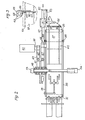
- Figur 1 eine Seitenansicht der Wickelvorrichtung in schematischer Darstellung,
- Figur 2 eine Draufsicht auf die Wickelvorrichtung nach Fig. 1 und
- Figur 3 eine Draufsicht auf die Einrichtung zum Andrücken der Haltebänder auf die fertig gewickelte Schuppenbandrolle.
- FIG. 1 shows a side view of the winding device in a schematic illustration,
- Figure 2 is a plan view of the winding device according to Fig. 1 and
- Figure 3 is a plan view of the device for pressing the straps onto the finished wound scale tape roll.
Die aufzuwickelnden flachen Werkstücke oder Säcke werden in der aus Fig. ersichtlichen Weise in Schuppenformation auf einem Förderband der Wickelvorrichtung zugeführt. Da der Schuppenabstand.der ankommenden Werkstücke unter Umständen unterschiedlich ist, ist eine Einrichtung zur Vergleichmäßigung des Schuppenabstandes vorgesehen, damit eine gleichmäßig gewickelte Schuppenbandrolle gebildet werden kann. Diese Einrichtung weist eine Andrücksrolle 25 auf. Auf der gegenüberliegenden Seite, also unterhalb der Schuppe, ist ein Fühler 26 angeordnet, der die Werkstückenden abtastet, dessen Impulse an eine elektrische Zwischenschaltung 27 weitergegeben werden.The flat workpieces or sacks to be wound are fed in the form shown in FIG. 1 in a scale formation on a conveyor belt of the winding device. Since the scale spacing of the incoming workpieces may differ, a device for equalizing the scale spacing is provided so that a uniformly wound scale tape roll can be formed. This device has a
Die Schuppe wird nach der Abtastung durch den Fühler 26 auf ein endloses, aus einzelnen Gurten gebildetes Förderband 28 abgeworfen, das über die Rollen 29 bis 34 läuft, die in einem schwenkbaren Gestell 35 drehbar gelagert sind. Am Gestell 35 ist auch die Antriebswalze 36 befestigt, über das die Trume zu den Rollen 29 zurückgeführt werden. Das Gestell 35 ist um die Achse der Rollen 31 schwenkbar gelagert und wird etwa unter der zu wickelnden Vorratsrolle 37 durch Pneumatikzylinder 38 abgestützt, die die Aufgabe haben, das Gestell 35 der Vorratsrolle 37 nachzuführen, um Unrundheiten der Vorratsrolle 37, die während des Wickelns auftreten können, auszugleichen. Außerdem ist eine Vorratswelle 39 auf flurfester Lagerung vorgesehen, von der Haltebänder 40 abgezogen werden, die in bekannter Weise in Lagen mit den Werkstücken auf der Vorratsrolle 37 aufgewickelt werden.After being scanned by the
Die Achse der Antriebswalze 36 ist mit einem Drehimpulsgeber 41 ausgestattet, dessen Impulse auf einen Zähler 42 eingegeben werden. Der Zähler 42 und der nicht dargestellte Antriebsmotor der Antriebswalze 36 sind mit der Zwischenschaltung 27 elektrisch verbunden. Der Zähler 42 kann auf eine vorbestimmte Zahl eingestellt werden und ist so geschaltet, daß der Antriebsmotor nach Erreichen dieser Zahl stillgesetzt wird. Die vorbestimmte Zahl wird etwas größer gewählt als dem beabsichtigten Schuppenband entspricht. Durch den Fühler 26 wird beim Vorbeigang eines Werkstückendes der Zähler 42 auf Null zurückgestellt. Bleibt also ein Werkstück aus, so daß der Zähler 42 die vorbestimmte Zahl erreicht, wird das Förderband 28 stillgesetzt und es beginnt erst dann wieder nach Durchlauf des nächsten Werkstücks anzulaufen. Daher wird auf dem Förderband 28 annähernd gleicher Schuppenabstand erzielt.The axis of the
Der Kern 45 der Vorratsrolle 37 wird durch einen Zapfen 46 gehalten, der im freien Ende eines Hebels 47 befestigt ist. Das andere Ende des Hebels 47 ist auf einer Buchse 48 zusammen mit einem zweiten Hebelarm 49 drehbar gelagert. Der Hebelarm 49 trägt einen dem Zapfen 46 entsprechenden Zapfen 50 an seinem freien Ende, der jedoch sich in entgegengesetzter Richtung erstreckt. An die Hebelarme 47 und 49 sind Druckmittelzylinder 51, 52 angelenkt, mit denen sie bzw. die Vorratsrolle 37 auf das Förderband 28 abgesenkt und von dort angehoben werden können.The
Die Buchse 48 ist leichtgängig längsverschieblich auf einer Achse 53 gelagert, die in einem beidseitig neben dem Förderband 28 angeordneten Ständer 54 befestigt ist. Mit der Buchse 48 ist ein Führungsteil 55 durch einen Steg 56 verbunden. Auf dem Führungsteil 55 ist lose drehbar eine Rolle 57 angebracht, die in einem U-Eisen 58 läuft, das die beiden Ständer 54 verbindet. Die freien Enden der Druckmittelzylinder 51, 52 sind am Führungsteil 56 angelenkt. Die Buchse 48 kann nun mit den Hebeln 47, 49 verschoben werden, so daß einmal der Zapfen 46 sich über dem Förderband 28 und der Zapfen 50 sich außerhalb des Aufwickelbereiches befindet. Während auf dem Zapfen 46 eine neue Vorratsrolle 37 aufgewickelt wird, kann die fertige Vorratsrolle vom Zapfen 50 abgenommen und ein neuer Kern 45 vorbereitet werden. Nach dem Fertigstellen der Vorratsrolle 37 auf dem Zapfen 46 wird diese mittels des Druckmittelzylinders 51 von dem Förderband 28 abgehoben und die Buchse 48 in ihre andere Extremstellung verschoben sowie die Vorratsrolle 37 auf dem Hallenboden abgesenkt und vom Zapfen 46 abgezogen.The
Bei den die Hebel 47, 49 mit dem schlittenförmigen Führungsteil 55 verbindenden Druckmittelzylindern 51, 52 handelt es sich um hydraulische Kolben-Zylinder-Einheiten, während die über das rahmenförmige Gestell 35 laufenden Förderbänder durch einen Pneumatikzylinder 38 an den Wickelkern bzw. die sich bildende Schuppenbandrolle 37 angedrückt werden. Der Pneumatikzylinder 38 hat etwa einen Hub von 100 mm und wird dadurch in seiner Mittellage gehalten, daß die Hydraulikzylinder 51, 52 die Hebel 47, 49 entsprechend dem Wickelfortschritt anheben. Die Hydraulikzylinder 51, 52 können dadurch betätigt werden, daß der Pneumatikzylinder mit einem Endschalter versehen ist. Der Pneumatikzylinder 38 hat gute federnde Eigenschaften, so daß er Unrundheiten der sich bildenden Schuppenbandrolle 37 auszugleichen vermag.The
Nachdem die Rolle 37 ihren vorgesehenen Durchmesser erreicht hat, werden die Haltebänder 40 noch ca. zwei weitere Umdrehungen um die Rolle 37 gewickelt. Danach wird die Preßeinrichtung 60 eingeschaltet und diese hält die Bänder 40 fest, wenn die Rolle von den Preßbändern bzw. dem Schuppenband 33, 28 abgehoben wird. Die manuelle Fixierung der Bändchen erfolgt erst, wenn die leere Rolle in der Aufnahmestation liegt.After the
Die Preßeinrichtung 60 ist auf einem Arm 61 montiert, der mit dem Hebel 47 fest verbunden ist. Am Arm 61 ist ein Querträger 62 befestigt, an dessen freiem Ende ein Druckzylinder 63 angelenkt ist. Die Kolbenstange des Druckzylinders 63 ist an einem Hebel 64 angelenkt. Ein Ende des Hebels 64 ist mit einem Bock 65 gelenkig verbunden. Mit dem anderen Ende des Hebels 64 ist eine Traverse 66 wippenartig gelenkig verbunden, an der Druckstücke 67 angelenkt sind, die auf die um die Vorratsrolle 37 herumgewickelten Haltebänder 50 bei Betätigen des Druckzylinders 63 drücken können.The
Der Bock 65 umfaßt hälftig den Arm 61. Auf gleicher Höhe am Arm 61 sitzt ein zweiter, symmetrisch zum Bock 65 ausgebildeter Bock 68, der mit dem Bock 65 durch Schrauben 69 verbunden und zusammen mit ihm auf den Arm 61 aufgeklemmt ist.The
Eine entsprechend ausgebildete zweite Preßeinrichtung 60 ist auf dem Arm 49 angeordnet. Diese ist jedoch in Fig. 2 nicht dargestellt.A correspondingly designed second
Claims (9)
Applications Claiming Priority (4)
| Application Number | Priority Date | Filing Date | Title |
|---|---|---|---|
| DE3048721 | 1980-12-23 | ||
| DE3048721 | 1980-12-23 | ||
| DE3135575A DE3135575C2 (en) | 1980-12-23 | 1981-09-08 | Device for the production of flaky belt rolls |
| DE3135575 | 1981-09-08 |
Publications (2)
| Publication Number | Publication Date |
|---|---|
| EP0054973A1 EP0054973A1 (en) | 1982-06-30 |
| EP0054973B1 true EP0054973B1 (en) | 1985-11-21 |
Family
ID=25789980
Family Applications (1)
| Application Number | Title | Priority Date | Filing Date |
|---|---|---|---|
| EP81110742A Expired EP0054973B1 (en) | 1980-12-23 | 1981-12-23 | Device for producing rolls of flexible sheets wound in staggered overlapping formation |
Country Status (3)
| Country | Link |
|---|---|
| EP (1) | EP0054973B1 (en) |
| DE (1) | DE3135575C2 (en) |
| ES (1) | ES508262A0 (en) |
Cited By (1)
| Publication number | Priority date | Publication date | Assignee | Title |
|---|---|---|---|---|
| DE4221911A1 (en) * | 1992-07-03 | 1994-01-05 | Kolbus Gmbh & Co Kg | Method for stacking printed sheets and device for carrying out the method |
Families Citing this family (2)
| Publication number | Priority date | Publication date | Assignee | Title |
|---|---|---|---|---|
| RU1804426C (en) * | 1986-05-02 | 1993-03-23 | Фераг Аг | Apparatus for winding printed production, fed by cascades, into portable rolls and binding obtained rolls |
| CH679993A5 (en) * | 1987-03-06 | 1992-05-29 | Ferag Ag |
Family Cites Families (6)
| Publication number | Priority date | Publication date | Assignee | Title |
|---|---|---|---|---|
| FR857390A (en) * | 1939-07-05 | 1940-09-09 | Rkoppwerke Ag Du | Device for lifting and unwinding fabric bales |
| FR1604539A (en) * | 1967-10-10 | 1971-11-29 | ||
| US3845915A (en) * | 1970-07-29 | 1974-11-05 | Kalle Ag | Winding machine |
| DE2349439A1 (en) * | 1973-10-02 | 1975-04-03 | Heinrich Schnell | DEVICE ON LOOSE FLORBOBINE WINDERS |
| DE2544135C2 (en) * | 1975-10-02 | 1982-11-25 | Windmöller & Hölscher, 4540 Lengerich | Device for the production of shingled belt rolls from flat workpieces laid on top of each other |
| CH617408A5 (en) * | 1977-05-27 | 1980-05-30 | Ferag Ag |
-
1981
- 1981-09-08 DE DE3135575A patent/DE3135575C2/en not_active Expired
- 1981-12-22 ES ES508262A patent/ES508262A0/en active Granted
- 1981-12-23 EP EP81110742A patent/EP0054973B1/en not_active Expired
Cited By (1)
| Publication number | Priority date | Publication date | Assignee | Title |
|---|---|---|---|---|
| DE4221911A1 (en) * | 1992-07-03 | 1994-01-05 | Kolbus Gmbh & Co Kg | Method for stacking printed sheets and device for carrying out the method |
Also Published As
| Publication number | Publication date |
|---|---|
| ES8301175A1 (en) | 1982-12-01 |
| ES508262A0 (en) | 1982-12-01 |
| DE3135575C2 (en) | 1985-09-12 |
| DE3135575A1 (en) | 1982-08-12 |
| EP0054973A1 (en) | 1982-06-30 |
Similar Documents
| Publication | Publication Date | Title |
|---|---|---|
| DE4401959C2 (en) | Carrier drum roller for a paper machine | |
| DE3119657C2 (en) | Method and machine for the production of packaging units | |
| EP0498962B1 (en) | Method and means for realising a wound bobbin | |
| EP0054903B1 (en) | Packaging apparatus for rolls with interior sleeves | |
| EP0054735B1 (en) | Device for producing rolls of flexible sheets wound in staggered overlapping formation | |
| DE2658294C2 (en) | Device for separating and feeding flat objects stored in a reel of shingled belts with retaining straps to subsequent stations | |
| EP0135080B1 (en) | Device for winding a plurality of printed sheets | |
| EP0538566B1 (en) | Device for winding a web of material onto core tubes | |
| EP0054973B1 (en) | Device for producing rolls of flexible sheets wound in staggered overlapping formation | |
| DE3643026C2 (en) | ||
| DE3914776A1 (en) | METHOD AND DEVICE FOR WINDING AND CROSS-CUTTING A RUNNING GOODS | |
| DE4135101A1 (en) | COIL FEEDING DEVICE FOR PAPER REEL REPLACEMENT IN ROTARY PRINTING MACHINES | |
| DE4039048C2 (en) | Winding device for winding a continuously fed plastic web | |
| DE3838563A1 (en) | DEVICE FOR STACKING FLAT OBJECTS | |
| EP0232553A1 (en) | Winding device for a continuously arriving imbricated batch of flexible flat products | |
| EP0406581B1 (en) | Arrangement for chopping of a web on a reversing winder | |
| EP0514334B1 (en) | Compression apparatus in wrapping machines for making tubular packages from printed products | |
| EP0093950A1 (en) | Method and device for winding webs | |
| DE3139290A1 (en) | Device for the production of imbricated band rolls consisting of flat flexible articles deposited in overlapping formation | |
| DE2243504C2 (en) | Device for the continuous winding of a film web onto winding tubes | |
| DE2619954B2 (en) | Method and device for the continuous treatment of a strip or wire-shaped material web | |
| DE2203696A1 (en) | MULTIPLE WRAPPING MACHINE WITH CONTACT ROLLER SYSTEM | |
| DE2249367C3 (en) | Device for continuously winding up thin, web-shaped goods | |
| DE2519767B2 (en) | PRODUCTION AND FURTHER PROCESSING OF IMBALANCE BALANCING WEIGHTS | |
| DE102013214531A1 (en) | Sheet processing machine e.g. sheet-fed offset printing machine has support structure provided with sheet that contacts with to-be-driven element, such that sheet and arc shaped portion are moved relatively |
Legal Events
| Date | Code | Title | Description |
|---|---|---|---|
| PUAI | Public reference made under article 153(3) epc to a published international application that has entered the european phase |
Free format text: ORIGINAL CODE: 0009012 |
|
| AK | Designated contracting states |
Designated state(s): FR GB IT |
|
| 17P | Request for examination filed |
Effective date: 19821123 |
|
| ITF | It: translation for a ep patent filed |
Owner name: BUGNION S.P.A. |
|
| GRAA | (expected) grant |
Free format text: ORIGINAL CODE: 0009210 |
|
| AK | Designated contracting states |
Designated state(s): FR GB IT |
|
| ET | Fr: translation filed | ||
| PLBE | No opposition filed within time limit |
Free format text: ORIGINAL CODE: 0009261 |
|
| STAA | Information on the status of an ep patent application or granted ep patent |
Free format text: STATUS: NO OPPOSITION FILED WITHIN TIME LIMIT |
|
| 26N | No opposition filed | ||
| ITTA | It: last paid annual fee | ||
| PGFP | Annual fee paid to national office [announced via postgrant information from national office to epo] |
Ref country code: GB Payment date: 19971121 Year of fee payment: 17 |
|
| PGFP | Annual fee paid to national office [announced via postgrant information from national office to epo] |
Ref country code: FR Payment date: 19971215 Year of fee payment: 17 |
|
| PG25 | Lapsed in a contracting state [announced via postgrant information from national office to epo] |
Ref country code: GB Free format text: LAPSE BECAUSE OF NON-PAYMENT OF DUE FEES Effective date: 19981223 |
|
| GBPC | Gb: european patent ceased through non-payment of renewal fee |
Effective date: 19981223 |
|
| PG25 | Lapsed in a contracting state [announced via postgrant information from national office to epo] |
Ref country code: FR Free format text: LAPSE BECAUSE OF NON-PAYMENT OF DUE FEES Effective date: 19990831 |
|
| REG | Reference to a national code |
Ref country code: FR Ref legal event code: ST |