EP0054256A2 - Cliquet d'arrêt pour une broche - Google Patents
Cliquet d'arrêt pour une broche Download PDFInfo
- Publication number
- EP0054256A2 EP0054256A2 EP81110284A EP81110284A EP0054256A2 EP 0054256 A2 EP0054256 A2 EP 0054256A2 EP 81110284 A EP81110284 A EP 81110284A EP 81110284 A EP81110284 A EP 81110284A EP 0054256 A2 EP0054256 A2 EP 0054256A2
- Authority
- EP
- European Patent Office
- Prior art keywords
- spindle
- collar
- cam follower
- cammed
- key
- Prior art date
- Legal status (The legal status is an assumption and is not a legal conclusion. Google has not performed a legal analysis and makes no representation as to the accuracy of the status listed.)
- Withdrawn
Links
Images

Classifications
-
- B—PERFORMING OPERATIONS; TRANSPORTING
- B23—MACHINE TOOLS; METAL-WORKING NOT OTHERWISE PROVIDED FOR
- B23Q—DETAILS, COMPONENTS, OR ACCESSORIES FOR MACHINE TOOLS, e.g. ARRANGEMENTS FOR COPYING OR CONTROLLING; MACHINE TOOLS IN GENERAL CHARACTERISED BY THE CONSTRUCTION OF PARTICULAR DETAILS OR COMPONENTS; COMBINATIONS OR ASSOCIATIONS OF METAL-WORKING MACHINES, NOT DIRECTED TO A PARTICULAR RESULT
- B23Q5/00—Driving or feeding mechanisms; Control arrangements therefor
- B23Q5/02—Driving main working members
- B23Q5/04—Driving main working members rotary shafts, e.g. working-spindles
-
- B—PERFORMING OPERATIONS; TRANSPORTING
- B23—MACHINE TOOLS; METAL-WORKING NOT OTHERWISE PROVIDED FOR
- B23Q—DETAILS, COMPONENTS, OR ACCESSORIES FOR MACHINE TOOLS, e.g. ARRANGEMENTS FOR COPYING OR CONTROLLING; MACHINE TOOLS IN GENERAL CHARACTERISED BY THE CONSTRUCTION OF PARTICULAR DETAILS OR COMPONENTS; COMBINATIONS OR ASSOCIATIONS OF METAL-WORKING MACHINES, NOT DIRECTED TO A PARTICULAR RESULT
- B23Q16/00—Equipment for precise positioning of tool or work into particular locations not otherwise provided for
- B23Q16/02—Indexing equipment
- B23Q16/04—Indexing equipment having intermediate members, e.g. pawls, for locking the relatively movable parts in the indexed position
-
- B—PERFORMING OPERATIONS; TRANSPORTING
- B23—MACHINE TOOLS; METAL-WORKING NOT OTHERWISE PROVIDED FOR
- B23Q—DETAILS, COMPONENTS, OR ACCESSORIES FOR MACHINE TOOLS, e.g. ARRANGEMENTS FOR COPYING OR CONTROLLING; MACHINE TOOLS IN GENERAL CHARACTERISED BY THE CONSTRUCTION OF PARTICULAR DETAILS OR COMPONENTS; COMBINATIONS OR ASSOCIATIONS OF METAL-WORKING MACHINES, NOT DIRECTED TO A PARTICULAR RESULT
- B23Q5/00—Driving or feeding mechanisms; Control arrangements therefor
- B23Q5/02—Driving main working members
- B23Q5/04—Driving main working members rotary shafts, e.g. working-spindles
- B23Q5/20—Adjusting or stopping working-spindles in a predetermined position
-
- Y—GENERAL TAGGING OF NEW TECHNOLOGICAL DEVELOPMENTS; GENERAL TAGGING OF CROSS-SECTIONAL TECHNOLOGIES SPANNING OVER SEVERAL SECTIONS OF THE IPC; TECHNICAL SUBJECTS COVERED BY FORMER USPC CROSS-REFERENCE ART COLLECTIONS [XRACs] AND DIGESTS
- Y10—TECHNICAL SUBJECTS COVERED BY FORMER USPC
- Y10T—TECHNICAL SUBJECTS COVERED BY FORMER US CLASSIFICATION
- Y10T29/00—Metal working
- Y10T29/51—Plural diverse manufacturing apparatus including means for metal shaping or assembling
- Y10T29/5152—Plural diverse manufacturing apparatus including means for metal shaping or assembling with turret mechanism
- Y10T29/5165—Plural diverse manufacturing apparatus including means for metal shaping or assembling with turret mechanism including rotating and/or locking means
-
- Y—GENERAL TAGGING OF NEW TECHNOLOGICAL DEVELOPMENTS; GENERAL TAGGING OF CROSS-SECTIONAL TECHNOLOGIES SPANNING OVER SEVERAL SECTIONS OF THE IPC; TECHNICAL SUBJECTS COVERED BY FORMER USPC CROSS-REFERENCE ART COLLECTIONS [XRACs] AND DIGESTS
- Y10—TECHNICAL SUBJECTS COVERED BY FORMER USPC
- Y10T—TECHNICAL SUBJECTS COVERED BY FORMER US CLASSIFICATION
- Y10T409/00—Gear cutting, milling, or planing
- Y10T409/30—Milling
- Y10T409/309352—Cutter spindle or spindle support
-
- Y—GENERAL TAGGING OF NEW TECHNOLOGICAL DEVELOPMENTS; GENERAL TAGGING OF CROSS-SECTIONAL TECHNOLOGIES SPANNING OVER SEVERAL SECTIONS OF THE IPC; TECHNICAL SUBJECTS COVERED BY FORMER USPC CROSS-REFERENCE ART COLLECTIONS [XRACs] AND DIGESTS
- Y10—TECHNICAL SUBJECTS COVERED BY FORMER USPC
- Y10T—TECHNICAL SUBJECTS COVERED BY FORMER US CLASSIFICATION
- Y10T483/00—Tool changing
- Y10T483/17—Tool changing including machine tool or component
- Y10T483/1733—Rotary spindle machine tool [e.g., milling machine, boring, machine, grinding machine, etc.]
- Y10T483/1736—Tool having specific mounting or work treating feature
- Y10T483/1743—Tool having specific mounting or work treating feature including means for angularly orienting tool and spindle
- Y10T483/1745—Spindle angularly oriented to align with tool
Definitions
- This invention relates generally to machine tools having rotatable, toolholding spindles, and more specifically, to a spindle keylock for stopping and locking the spindle of a machine tool at a predetermined angular orientation with respect to a fixed plane passing through the spindle axis.
- U.S. Patent 3,704,510 discloses a servo control system which utilizes a position synchro to control spindle drive motor excitation so that spindle rotation ceases and a braking force is applied to the spindle to locate the spindle at a predetermined angular orientation, thereby assuring that the spindle key aligns with a complementary toolholder key.
- a somewhat different servo control system is described in U.S. Patent 3,874,071.
- a pair of synchro generators one for measuring the angular toolholder position and the other for measuring the angular spindle position, are coupled to a control system which controls the rotation of a socket in the arm which transfers tools between the tool storage drum and the tool transfer arm.
- the control system forces the socket in the arm to rotate in accordance with the difference between output signals of the synchro generators so that the key of the toolholder carried by the arm will, when transferred by tool transfer arm from the socket to the spindle, be aligned with the spindle key.
- the prior art servo controlled spindle keylock apparatus are believed subject to the disadvantage that they result in increased machine complexity and cost.
- the spindle keylock apparatus described in each of the above- identified patents includes a pair of pivotally mounted claws which are urged by a solenoid or the like energized through a proximity switch to engage a dog that-extends radially from the spindle.
- the above- described spindle keylock apparatus are each believed subject to the disadvantage that machine tool wear and vibration will likely cause proximity switch misalignment which may result in locking and stopping of the spindle at a position other than the predetermined angular position.
- spindle keylock apparatus includes the spindle keylock apparatus described in U.S. Patent Nos. 3,604,803 and 3,691,899.
- the spindle keylock apparatus described in these patents comprises a double helical cam which is urged by an actuator against a cam follower carried by a sleeve keyed to a shaft coupled by a set of gears to the spindle. As the cam engages the cam follower, the sleeve, the shaft, and hence, the spindle, all rotate until the cam follower reaches the top of a cam, at which time the spindle will have reached its predetermined angular position.
- the spindle locking apparatus is believed to suffer from the following disadvantage. Since the cam follower is carried on a sleeve keyed to a shaft coupled by gears to the spindle rather than being carried by the spindle itself, the spindle may not always be positioned in a precise angular orientation due to play between the cam follower and the spindle.
- U.S. Patent 4,051,583 describes a spindle locking device apparatus which, like the spindle lock apparatus described above operates on a shaft coupled by gears to the spindle rather than on the spindle itself and is thus believed to suffer from the same disadvantage.
- the present invention concerns a spindle keylock apparatus for stopping and locking the spindle of a machine tool at precise angular orientation without the disadvantages and drawbacks attributable to other prior art devices.
- the present invention provides apparatus for stopping and locking a machine tool spindle journalled for rotation to the machine tool spindle head at a predetermined angular orientation with respect to a fixed plane passing through the spindle axis in alignment with the spindle key, characterized by a collar adapted to be fastened about said spindle for co-joint rotation therewith, said collar having an exterior cammed surface in which is inscribed an axially extending slot; cam follower means adapted to be pivotally mounted to the machine tool spindlehead and lying within a plane passing through the spindle axis which is at a predetermined angular orientation with respect to said fixed plane, said cam follower means being rotatable about an axis perpendicular to the axis of the spindle for following the cammed surface on said collar; and actuating means adapted to be fastened to said spindlehead and coupled to said cam follower means for urging said cam follower means against the cammed surface of said collar so that said cam follower means will follow the
- Fig. 1 illustrates a partial, cut-away view of a machine tool comprising a tool carrying spindle 10 which is journaled for rotation to a spindlehead 12 by bearings 14.
- a pair of gears 16a and 16b are keyed to spindle 10 for co-joint rotation therewith.
- Gears 16 a and 16b are driven by a motor (.not shown) through a cluster gear 20 which has a pair of gear members 20a and 20b, each dimensioned to me hingly engage a respective one of gears 16a and 16b on spindle 10.
- Cluster gear 20 is slidably mounted for transverse movement along an axis parallel to the axis of spindle 10 between a first position where gear member 20a meshes with gear 16a and a second position where gear member 20b meshes with gear 16b..
- gear member 20a meshes with gear 16a
- gear member 20b meshes with gear 16b.
- spindlehead 12 comprises a frame having a set of passages therein to permit access inside the spindlehead.
- a set of access plates 22a and 22b are fastened to spindlehead 12 by bolts 24 to overlie the spindlehead access passages so as to prevent entry of foreign matter into the spindlehead.
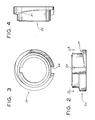
- an annular collar 26 is carried on spindle 10 for co-joint rotation therewith. As best illustrated in Figs. 2, 3, and 4, collar 26 has a helically cammed exterior surface 27 into which an axially extending slot 28 or channel is inscribed, slot 28 being best illustrated in Figs. 2 and 3.
- collar 26 and spindle 10 rotate co-jointly the spindle key (not shown) is always at a fixed angular orientation with respect to slot 28.
- collar 26 is illustrated in Figs. 2-4 as being comprised of a single member formed either by casting or forging, in certain instances, it may be desirable to configure collar 26 of two or more geometric sections fastened together by bolts or the like.
- a cam follower 30, taking the form of a key or the like is pivotally mounted to a block 31 by a pin 32 so as to be rotatable about an axis perpendicular to spindle 10.
- Block 31 is mounted to access plate 22a such that key 30 lies in a plane which is at a predetermined angular orientation with a fixed plane passing through the spindle axis in alignment with the spindle key.
- An actuator 34 typically comprised of a solenoid or an air cylinder, is fastened to access plate 22a.
- the spindle or arm of actuator 34 is connected to key 30 by means of a pin 36, so that when actuator 34 is actuated by the machine tool control system (_not shown) which causes the actuator spindle to be drawn into the actuator, key 30 is urged against the cammed surface of collar 26.
- the motor driving cluster gear 20 is caused to rotate spindle 10 very slowly under control of the machine tool control system.
- actuator 32 is actuated to urge key 30 against the cammed surface of collar 26, causing the key to ride on the cammed collar surface until it engages the axially extending slot inscribed in the collar surface to stop and lock the spindle.
- key 30 When key 30 fully engages the axially extending collar slot, it bears against a proximity switch 38 connected to the machine tool control system, causing the motor driving cluster gear 20 to be de-energized.
- key 30 Since key 30 is at a predetermined angular orientation with respect to the fixed reference plane passing through the spindle in alignment with the spindle key, key 30, will, when it engages slot 28, always stop and lock the spindle at the predetermined angular orientation.regardless of where key 30 initially.engages the cammed collar surface since the cammed collar surface always steers key 30 right into slot 28.
- the foregoing describes a simple spindle keylock apparatus, comprised of a cammed collar surrounding the spindle and a cam follower which is urged by an actuator against the cammed surface to stop and lock the collar and hence the spindle in a predetermined angular orientation. Because of its simple construction, the spindle keylock apparatus of the present invention may be retrofitted to existing spindles.
Landscapes
- Engineering & Computer Science (AREA)
- Mechanical Engineering (AREA)
- Automatic Tool Replacement In Machine Tools (AREA)
- Jigs For Machine Tools (AREA)
Applications Claiming Priority (2)
| Application Number | Priority Date | Filing Date | Title |
|---|---|---|---|
| US215911 | 1980-12-12 | ||
| US06/215,911 US4356609A (en) | 1980-12-12 | 1980-12-12 | Spindle keylock |
Publications (2)
| Publication Number | Publication Date |
|---|---|
| EP0054256A2 true EP0054256A2 (fr) | 1982-06-23 |
| EP0054256A3 EP0054256A3 (fr) | 1983-08-24 |
Family
ID=22804913
Family Applications (1)
| Application Number | Title | Priority Date | Filing Date |
|---|---|---|---|
| EP81110284A Withdrawn EP0054256A3 (fr) | 1980-12-12 | 1981-12-09 | Cliquet d'arrêt pour une broche |
Country Status (7)
| Country | Link |
|---|---|
| US (1) | US4356609A (fr) |
| EP (1) | EP0054256A3 (fr) |
| JP (1) | JPS57121439A (fr) |
| KR (1) | KR830007214A (fr) |
| BR (1) | BR8108023A (fr) |
| CA (1) | CA1167668A (fr) |
| IL (1) | IL64408A (fr) |
Families Citing this family (10)
| Publication number | Priority date | Publication date | Assignee | Title |
|---|---|---|---|---|
| US4520550A (en) * | 1983-05-27 | 1985-06-04 | Automated Robotic Systems, Inc. | Robot tool changer |
| US4654957A (en) * | 1984-06-22 | 1987-04-07 | Ex-Cell-O Corporation | Flexible machining apparatus with single shank tool and multi-spindle tool head changing and operating capabilities |
| DE3632106C1 (de) * | 1986-09-22 | 1988-04-14 | Maho Ag | Vorrichtung zur Winkelpositionierung einer Arbeitsspindel |
| US4764064A (en) * | 1987-09-25 | 1988-08-16 | Komo Machine Incorporated | Tool changer |
| DE4031991A1 (de) * | 1990-10-09 | 1992-04-16 | Chiron Werke Gmbh | Werkzeugmaschine |
| JP2582284Y2 (ja) * | 1992-08-31 | 1998-09-30 | 光洋精工株式会社 | 回転工具アダプタの回り止め機構 |
| US5860775A (en) * | 1996-06-05 | 1999-01-19 | Hyundai Motor Company | Spindle position orientation apparatus of boring machine |
| US5954623A (en) * | 1997-10-07 | 1999-09-21 | Davis; Steven E. | Tool changer apparatus and method of automating a machine tool |
| SE9901053L (sv) * | 1999-03-23 | 2000-02-28 | Lind Finance & Dev Ab | Anordning vid verktygsspindel |
| SE9901052L (sv) * | 1999-03-23 | 2000-02-28 | Lind Finance & Dev Ab | Anordning vid verktygsspindel |
Citations (4)
| Publication number | Priority date | Publication date | Assignee | Title |
|---|---|---|---|---|
| DE2306590A1 (de) * | 1973-02-10 | 1974-08-22 | Gildemeister Ag | Einrichtung an mehrspindel-drehautomaten zum stillsetzen der drehspindeln in bestimmten winkelstellungen |
| DE2708049A1 (de) * | 1976-02-26 | 1977-09-08 | Tornos Sa Fabrique De Machine | Einrichtung zum stillsetzen der werkstueckspindel in bestimmter winkelstellung an einem langdrehautomaten mit laengsverschiebbarem spindelstock |
| DE1777294B2 (de) * | 1960-08-18 | 1978-01-12 | Ausscheidung aus 14 02 985 Kearney & Trecker Corp, Milwaukee, Wis (VStA) | Werkzeugwechselvorrichtung fuer eine werkzeugmaschine |
| DE3126223A1 (de) * | 1980-07-10 | 1982-05-13 | Litton Industrial Products Inc., 17268 Waynesboro, Pa. | Rundschleifmaschine |
Family Cites Families (20)
| Publication number | Priority date | Publication date | Assignee | Title |
|---|---|---|---|---|
| US3709623A (en) * | 1960-04-27 | 1973-01-09 | New Britain Machine Co | Combined boring, drilling and milling machine |
| US3704510A (en) * | 1962-03-13 | 1972-12-05 | Kearney & Trecker Corp | Machine tool with tool changer |
| US3135980A (en) * | 1963-08-16 | 1964-06-09 | Sundstrand Corp | Tool supporting adapter having means to coact with a transport means for orientationof the adapter with the spindle head |
| DE1752834C3 (de) * | 1967-07-29 | 1979-01-25 | Ing. C. Olivetti & C., S.P.A., Ivrea, Turin (Italien) | Antrieb für die Spindel einer Bohr- oder Fräsmaschine |
| US3581562A (en) * | 1969-04-28 | 1971-06-01 | Allspeeds Holdings Ltd | Torque-sensing devices |
| FR2049338A5 (fr) * | 1969-06-06 | 1971-03-26 | Berthiez C N M P | |
| GB1352846A (en) * | 1970-04-10 | 1974-05-15 | Herbert Ltd A | Lathe with chuck transfer mechanisms |
| JPS4888565A (fr) * | 1972-02-25 | 1973-11-20 | ||
| US3893371A (en) * | 1972-03-27 | 1975-07-08 | Houdaille Industries Inc | Method and means for operating a spindle drive in a machine tool |
| US3824891A (en) * | 1973-05-11 | 1974-07-23 | Litton Industrial Products | Machine tool |
| JPS5742463B2 (fr) * | 1974-08-25 | 1982-09-08 | ||
| JPS5148876A (en) * | 1974-10-23 | 1976-04-27 | Toyoda Machine Works Ltd | Jidokogukokansochi |
| JPS51126586A (en) * | 1975-04-28 | 1976-11-04 | Toyoda Mach Works Ltd | Device for stopping the spindle of turret type machining center in fix ed phase |
| DE2526902B2 (de) * | 1975-06-16 | 1981-08-27 | Stama Stark Maschinenfabrik Gotthilf Stark Gmbh & Co, 7311 Schlierbach | Werkzeugwechselvorrichtung |
| US4075927A (en) * | 1975-11-06 | 1978-02-28 | Houdaille Industries, Inc. | Tool orienting and release mechanism for machine tool |
| JPS5292175A (en) * | 1976-01-29 | 1977-08-03 | Toyoda Mach Works Ltd | Machine tool which is provided with automatic tool changing device |
| SU657956A1 (ru) * | 1976-06-08 | 1979-04-25 | Специальное Конструкторское Бюро По Проектированию Алмазно-Расточных И Радиально-Сверлильных Станков | Устройство дл доворота и фиксировани шпиндел |
| US4173817A (en) * | 1977-04-25 | 1979-11-13 | Ex-Cell-O Corporation | Machining center with automatic tool changer |
| US4102035A (en) * | 1977-04-25 | 1978-07-25 | Ex-Cell-O Corporation | Machining center with automatic tool changer |
| DE2742404A1 (de) * | 1977-09-21 | 1979-03-29 | Thyssen Industrie | Positioniervorrichtung, z.b. fuer werkzeugmaschinen |
-
1980
- 1980-12-12 US US06/215,911 patent/US4356609A/en not_active Expired - Lifetime
-
1981
- 1981-11-20 CA CA000390583A patent/CA1167668A/fr not_active Expired
- 1981-11-30 IL IL64408A patent/IL64408A/xx unknown
- 1981-12-09 EP EP81110284A patent/EP0054256A3/fr not_active Withdrawn
- 1981-12-10 BR BR8108023A patent/BR8108023A/pt unknown
- 1981-12-11 JP JP56199947A patent/JPS57121439A/ja active Pending
- 1981-12-11 KR KR1019810004859A patent/KR830007214A/ko unknown
Patent Citations (4)
| Publication number | Priority date | Publication date | Assignee | Title |
|---|---|---|---|---|
| DE1777294B2 (de) * | 1960-08-18 | 1978-01-12 | Ausscheidung aus 14 02 985 Kearney & Trecker Corp, Milwaukee, Wis (VStA) | Werkzeugwechselvorrichtung fuer eine werkzeugmaschine |
| DE2306590A1 (de) * | 1973-02-10 | 1974-08-22 | Gildemeister Ag | Einrichtung an mehrspindel-drehautomaten zum stillsetzen der drehspindeln in bestimmten winkelstellungen |
| DE2708049A1 (de) * | 1976-02-26 | 1977-09-08 | Tornos Sa Fabrique De Machine | Einrichtung zum stillsetzen der werkstueckspindel in bestimmter winkelstellung an einem langdrehautomaten mit laengsverschiebbarem spindelstock |
| DE3126223A1 (de) * | 1980-07-10 | 1982-05-13 | Litton Industrial Products Inc., 17268 Waynesboro, Pa. | Rundschleifmaschine |
Also Published As
| Publication number | Publication date |
|---|---|
| IL64408A (en) | 1985-06-30 |
| IL64408A0 (en) | 1982-02-28 |
| BR8108023A (pt) | 1982-09-21 |
| US4356609A (en) | 1982-11-02 |
| EP0054256A3 (fr) | 1983-08-24 |
| CA1167668A (fr) | 1984-05-22 |
| JPS57121439A (en) | 1982-07-28 |
| KR830007214A (ko) | 1983-10-14 |
Similar Documents
| Publication | Publication Date | Title |
|---|---|---|
| EP0054256A2 (fr) | Cliquet d'arrêt pour une broche | |
| US4358228A (en) | Machine tool | |
| US4748357A (en) | Electromechanical apparatus for producing an axial force for actuating clamping devices | |
| US4573566A (en) | Dual stroke transfer drive | |
| US3893371A (en) | Method and means for operating a spindle drive in a machine tool | |
| DE60002027T2 (de) | Verfahren und Vorrichtung zur Steuerung einer elektromotorisch betriebenen Rolle | |
| DE19542048A1 (de) | Verfahren und Vorrichtung für die Übertragung von Drehantriebskräften an Spindeln | |
| EP0250609A1 (fr) | Boîte de vitesse entraînée par moteur avec relation entrée-sortie assurée | |
| US4656708A (en) | Live tooling turret | |
| US4449866A (en) | Servo-controlled spindle drive system | |
| US2945401A (en) | Machine tool | |
| GB1229479A (fr) | ||
| US4499792A (en) | Apparatus for angularly positioning a rotary member | |
| EP0318959A2 (fr) | Système d'entraînement pour une presse rotative | |
| US3909020A (en) | Apparatus for automatically controlling the size of the opening of the jaws of a chuck | |
| KR860001203Y1 (ko) | 공작기계의 스핀들 키이록크(Keylock) 장치 | |
| KR870002070B1 (ko) | 머시닝 센터(machining center)의 팔레트(pallet) 교환장치 | |
| JPH05599Y2 (fr) | ||
| JPS5843214B2 (ja) | 回転主軸の自動工具締結装置 | |
| SU1215884A1 (ru) | Многошпиндельна головка | |
| SU753551A1 (ru) | Автоматическа револьверна головка | |
| SU366056A1 (ru) | Подвижных органов станков12 | |
| DE2721122C2 (de) | Spindelstillsetzeinrichtung für Drehautomaten | |
| SU878414A1 (ru) | Токарный автомат | |
| SU955304A1 (ru) | Станок дл автоматического продораживани коллекторов электрических машин |
Legal Events
| Date | Code | Title | Description |
|---|---|---|---|
| PUAI | Public reference made under article 153(3) epc to a published international application that has entered the european phase |
Free format text: ORIGINAL CODE: 0009012 |
|
| AK | Designated contracting states |
Designated state(s): BE CH DE FR GB IT NL SE |
|
| 111L | Licence recorded |
Free format text: 0100 KEARNEY & TRECKER MARWIN LIMITED |
|
| PUAL | Search report despatched |
Free format text: ORIGINAL CODE: 0009013 |
|
| AK | Designated contracting states |
Designated state(s): BE CH DE FR GB IT LI NL SE |
|
| 17P | Request for examination filed |
Effective date: 19840109 |
|
| STAA | Information on the status of an ep patent application or granted ep patent |
Free format text: STATUS: THE APPLICATION IS DEEMED TO BE WITHDRAWN |
|
| 18D | Application deemed to be withdrawn |
Effective date: 19870127 |
|
| RIN1 | Information on inventor provided before grant (corrected) |
Inventor name: WOLLERMANN, KENNETH A. |