EP0053513A2 - Avalanche photodiodes - Google Patents
Avalanche photodiodes Download PDFInfo
- Publication number
- EP0053513A2 EP0053513A2 EP81305658A EP81305658A EP0053513A2 EP 0053513 A2 EP0053513 A2 EP 0053513A2 EP 81305658 A EP81305658 A EP 81305658A EP 81305658 A EP81305658 A EP 81305658A EP 0053513 A2 EP0053513 A2 EP 0053513A2
- Authority
- EP
- European Patent Office
- Prior art keywords
- layer
- light absorbing
- active layer
- semiconductor
- absorbing layer
- Prior art date
- Legal status (The legal status is an assumption and is not a legal conclusion. Google has not performed a legal analysis and makes no representation as to the accuracy of the status listed.)
- Granted
Links
Images


Classifications
-
- H—ELECTRICITY
- H10—SEMICONDUCTOR DEVICES; ELECTRIC SOLID-STATE DEVICES NOT OTHERWISE PROVIDED FOR
- H10F—INORGANIC SEMICONDUCTOR DEVICES SENSITIVE TO INFRARED RADIATION, LIGHT, ELECTROMAGNETIC RADIATION OF SHORTER WAVELENGTH OR CORPUSCULAR RADIATION
- H10F30/00—Individual radiation-sensitive semiconductor devices in which radiation controls the flow of current through the devices, e.g. photodetectors
- H10F30/20—Individual radiation-sensitive semiconductor devices in which radiation controls the flow of current through the devices, e.g. photodetectors the devices having potential barriers, e.g. phototransistors
- H10F30/21—Individual radiation-sensitive semiconductor devices in which radiation controls the flow of current through the devices, e.g. photodetectors the devices having potential barriers, e.g. phototransistors the devices being sensitive to infrared, visible or ultraviolet radiation
- H10F30/22—Individual radiation-sensitive semiconductor devices in which radiation controls the flow of current through the devices, e.g. photodetectors the devices having potential barriers, e.g. phototransistors the devices being sensitive to infrared, visible or ultraviolet radiation the devices having only one potential barrier, e.g. photodiodes
- H10F30/225—Individual radiation-sensitive semiconductor devices in which radiation controls the flow of current through the devices, e.g. photodetectors the devices having potential barriers, e.g. phototransistors the devices being sensitive to infrared, visible or ultraviolet radiation the devices having only one potential barrier, e.g. photodiodes the potential barrier working in avalanche mode, e.g. avalanche photodiodes
- H10F30/2255—Individual radiation-sensitive semiconductor devices in which radiation controls the flow of current through the devices, e.g. photodetectors the devices having potential barriers, e.g. phototransistors the devices being sensitive to infrared, visible or ultraviolet radiation the devices having only one potential barrier, e.g. photodiodes the potential barrier working in avalanche mode, e.g. avalanche photodiodes in which the active layers form heterostructures, e.g. SAM structures
Definitions
- the present invention relates to avalanche photodiodes (hereinafter referred to as APD's).
- An APD is a type of photodiode which can offer various performance advantages, such as higher grade avalanche gain, sensitivity and response time and lower values of dark-current and noise, as compared with other types. These advantages arise from an avalanche breakdown phenomenon which occurs at a p-n junction which is arranged in a multiplication layer in the APD which has a reverse bias applied thereto when the APD is in use to cause the avalanche multiplication of a current of electrons and/or holes generated in a light absorbing region of the device which is exposed to receive light arriving at that region.
- APD's require some means effective to limit breakdown to a central region of the above mentioned p-n junction.
- the wavelength of light to which an APD is sensitive is determined by the band gap Eg of the material of which the light absorbing layer of the APD is made.
- a combination of layers of semiconductor one of which has a relatively small band gap Eg and functions as a light absorbing layer and the other of which has a relatively large band gap Eg and functions as a multiplication layer, is convenient.
- a combination of In x Ga 1-x As 1-y P y and InP, or a combination of GaSb and Ga x Al 1-x Sb is preferably employed.
- Multilayered APD's employing the above mentioned group III-V compound or alloy semiconductors have been proposed which have a so-called self guard ring layer configuration,,,in which a p-n junction is formed for the purpose of avalanche multiplication slightly above the heterojunction between the light absorbing layer, of In x Ga 1-x As, In x Ga 1-x As 1-y P y or the like, and the multiplicationlayer, of InP or the like, whereby the intensity of electric field in the light absorbing layer is larger in the central region of the diode, or in a light absorbing region, than in other regions thereof, or in regions not exposed to light, causing the breakdown voltage of the p-n junction to become less in the central region of the diode which is exposed to light than in regions which are not exposed to light.
- the function of this so-called self guard ring configuration is based upon the characteristic that the band gap Eg of the group III-V compound or alloy semiconductor of which the light absorbing layer is made is less than the band gap Eg of t.he group III-V compound or alloy semiconductor of which the multiplication or active layer is made and that the breakdown voltage is less for the former than for the latter. It has been determined that this so-called self guard ring configuration provides an excellent guard ring effect.
- APD's having the so-called self guard ring configuration have a drawback as described below.
- the intensity of electric field is necessarily high in the light absorbing layer,'a tunnel current or a current component resulting from carriers directly excited by the high intensity of electric field has inevitably occur red in the light absorbing layer, giving rise to various adverse effects, e.g. relatively large amounts of dark current, noise or the like.
- the magnitude of tunnel effect is larger for a substance having a lesser band gap Eg, such as group III-V compound or alloy semiconductors, e.g. In x Ga 1-x As 1-y P y or GaSb and the like.
- the present invention is concerned with the provision of APD's which do not suffer from the above-mentioned drawback.
- Embodiments of the present invention can also afford various other advantages.
- the present invention provides a multilayer APD having a guard ring configuration which can readily realise an efficient guard ring effect without suffering the above- described tunnel current problem, as a result providing for the realisation of higher grades of avalanche-gain, sensitivity and response time and lower values of dark-current and noise.
- the present invention provides for an APD of a planar type.
- the present invention can provide an APD sensitive to light in a wavelength range 1.2 to 1.65 micrometers, which is provided with a light absorbing layer made of a group III-V compound or alloy semiconductor, for example In x Ga 1-x As 1-y P y or GaSb, and with a multiplication or active layer made of another group III-V alloy or compound semiconductor, for example InP or Ga x Al 1-x Sb, having a larger band gap Eg than that of the material of the light absorbing layer.
- a group III-V compound or alloy semiconductor for example In x Ga 1-x As 1-y P y or GaSb
- a multiplication or active layer made of another group III-V alloy or compound semiconductor, for example InP or Ga x Al 1-x Sb, having a larger band gap Eg than that of the material of the light absorbing layer.
- This invention can further provide a planar type APD having a more efficient guard ring effect, realising a more pronounced difference in breakdown voltage between the central region of the p-n junction and other regions thereof.
- This invention can also provide a planar type APD having a simple layer configuration, in which the number of essential design parameters is reduced from three to two, thereby allowing considerable freedom for design and production of the APD.
- the position of the p-n junction (e.g. the flat bottom of the p-n junction, in the light sensitive region) is in the neighbourhood of the interface between the middle layer and the active layer.
- Such an APD embodying the present invention has the following attributes:-
- This invention has a second embodiment which is an APD having :-
- Such an APD has the attribute that a more pronounced difference in breakdown voltages between the light sensitive region and the guard ring region is achieved, resulting in a more reliable guard ring effect.
- the present invention has a third embodiment which is an APD having :-
- Such an APD has the following attributes.
- APD's in accordance with the first and second broad embodiments of this invention will be provided in relation to APD's having an n-InP substrate, an n-InP buffer ,. an n-In x Ga 1-x As y P 1-y light absorbing layer,an n-InP middle layer, and an n-InP active layer, a limited, deep, region of the active layer being doped with a p-type impurity to form a light sensitive region which is surrounded by a shallow p-doped region forming a guard ring.
- Production of the layers of the APD's will be assumed to be effected by continuously growing the layers employing liquid phase epitaxy in one process. Of course, lattice matching is required between adjacent layers.
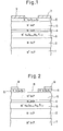
- a first step in the production of an APD in accordance with the first general embodiment of the present invention is the growth of an n-InP buffer layer 2 of a thickness of several micrometers and an n-impurity concentration of approximately 10 16 /cm 3 on an n-InP single crystal substrate 1 with an n-impurity concentration of approximately 10 /cm .
- the purpose of this step is simply to provide improved crystal conditions or surface conditions, and this step is not essential to the present invention but preferable.
- Technical significance of the above-mentioned values of impurity concentration and layer thickness are merely exemplary.
- a second step is to grow a light absorbing layer 3 of a thickness of 2 micrometers or more with an n-impurity concentration of 5 x 10 15 to 1 x 10 16 /cm 3 on the substrate 1, or preferably on the buffer layer 2.
- a third step is to grow an n-InP middle layer 4 of a thickness of 0.5 micrometers or less with an n-impurity concentration the same as or greater than that of the light absorbing layer 3, possibly more than 2 x 1 0 16 / cm 3 , on the light absorbing layer 3.
- a fourth step is to grow an n-InP active layer 5 of a thickness of approximately 2.5 micrometers and with an n-impurity concentration which is tenths, of that of the middle layer, or less, preferable 5 x 10 to 1 x 10 16 /cm 3 , on the middle layer 4.
- a fifth step is to grow an n-In x Ga 1-x As layer (hereinafter referred to as a mask layer) 6 on the active layer 5.
- This mask layer 6 is intended to act as a mask during subsequent etching and dif-fusion steps for the final purpose of producing a step shaped p-n junction as shown in Figure 3. Therefore, an arbitrary magnitude of n-type impurity concentration is allowed, save that it should not be such as to give rise to any adverse effect in relation to the impurity concentration of the active layer 5 during subsequent diffusion processes.
- the foregoing five steps are carried out in one process employing liquid phase epitaxy.
- a sixth step is to produce a resist photomask 7, resistant to sulphuric acid based solvents, on the mask 6 except for a part thereof corresponding to the light sensitive region.
- a seventh step is selectively to remove the portion of the mask layer 6 unmasked by the resist photomask 7.
- a convenient process for accomplishing this step is to soak the wafer in a solution containing three portions of sulphuric acid, one portion of hydrogen peroxide and one portion of water, because this solution does not dissolve InP , albeit it does dissive In x Ga 1-x As.
- An eighth step is to remove the resist photomask 7, before a silicon dioxide layer is grown on the wafer, more specifically on the mask layer 6 and partly on the active layer 5.
- Photolithography is employed to remove parts of the silicon dioxide layer from the regions corresponding to the light sensitive region and a guard ring region, in order to produce a mask 9 having an opening 8 on the light sensitive region and the guard ring region.
- a ninth step is to employ an impurity diffusion process to introduce a p-type impurity into an upper portion 10 of the active layer 5 to a high concentration such as 10 18 /cm 3 . Due to the stepped shape of the double-layered mask 9 and 6, a p-n junction itself of a stepped shape is produced. In other words, the depth of the p-n junction is much larger where the light sensitive region is confronted than in the guard ring region.
- This impurity diffusion process can be carried out at a temperature of 500 0 C employing CdP 2 as the impurity source.
- the p-n junction comprises a relatively deep part, produced at a depth of 1.5 micrometers, in the light sensitive region and a relatively shallow part which extends around the deep part and is produced at a depth of 0.5 micrometers in the area corresponding to the guard ring region .
- the deep part of the p-n junction is located 1 micrometer above the interface between the active layer 5 and the middle layer 4, and the relatively shallow part providing the guard ring is located 2 micrometers above the interface between the active layer 5 and the middle layer 4.
- a two hour period was required for the diffusion to form the stepped shape p-n junction.
- An alternative process as described below, can be employed for production of the stepped shape p-n junction.
- a recess is produced by means of an etching process applied to an area corresponding to the light sensitive region of the top surface of the n-InP active layer 5, rather than producing a mask made of SiO 2 layer 9 and the n-In x Ga 1-x As layer 6 as described above, before a p-type impurity is diffused in.
- This has the advantage of simplicity and in reduction in the number of heating processes required.
- a tenth step is to remove the Si0 2 layer 9 and the n-In x Ga 1-x As layer 6 both of which were employed in combination as a mask in the previous step, before producing an Si0 2 film 11 on the light sensitive region , which film 11 is to act as an anti-reflection coating, and another Si0 2 film 12 on the guard ring region and the region surrounding the guard ring region, which film 12 is to act as an insulator.
- Such films 11 and 12 are separated from one another by an area 13 on which an anode of the APD is to be produced. between the films 11 and 12.
- the removal of the layer 9 and the layer 6 can be readily carried out by soaking the wafer respectively in a solution containing fluoric acid and ammonium fluoride and a sulphuric acid based solvent. Chemical vapour deposition and photolithography are in combination employed for production of the films 11 and 12.
- the eleventh step is to produce an anode 14 and a cathode 15 respectively on the area 13 and on the bottom surface of the wafer.
- the anode and the cathode are produced by means of the vacuum evaporation of AuZn and AuGe respectively.
- the APD When such an APD is operated, the APD has applied thereto a negative voltage and a positive voltage respectively at its anode and cathode. Since the application of these voltages reverse biases the p-n junction produced in an APD whose layer configuration is as shown by way of example in Figure 5, a depletion layer extends across the p-n junction.
- the differential of intensity of electric field versus the distance from a p-n junction is proportional to the impurity concentration of the corresponding region.
- the depletion layer tends to extend far into the middle layer 4 and the light absorbing layer 3.
- the distance to which the depletion layer extends is different for the light sensitive region and for the region corresponding to the guard ring region.
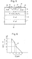
- the n-type impurity concentration is 8 x 10 15 /cm 3 for the active layer 5 and for the light absorbing layer 3 and is 2 x 10 16 /cm 3 for the middle layer 4, the relationships between the intensity of electric field and depth from the wafer surface are as shown in the graphs of Figures 6 and 7.
- the polygonal line A in the graph of Figure 6 illustrates the position in which a breakdown occurs in the light sensitive-region
- the polygonal line B in the graph of Figure 7 illustrates the position in which a breakdown occurs in the guard ring region .
- the intensities of electric field at the p-n junction, at the interface between the active layer 5 and the middle layer 4, and at the interface between the middle layer 4 and the light absorbing layer 3, are respectively 4.73 x 10⁵V/cm, 3.56 x 10⁵V/cm and 2.10 x 10 5 V/cm.
- the corresponding intensities of electric field are 4.73 x 10 5 V/cm, 2.39 x 10 5 V/cm and 0.93 x 10⁵V/cm respectively.
- the area surrounded by the solid line, A or B, and the X-axis relates to breakdown voltage.
- Figure 6 shows that the breakdown voltage in the light sensitive region is 75.6 V.
- Figure 7 shows that the breakdown voltage in the area facing the guard ring is 90.2 V. Since a fairly large difference, specifically 14.6 V, is manifest between the breakdown voltages for the light sensitive region and for the area facing the guard ring, an APD in accordance with an embodiment of this invention allows breakdown to occur only in the light sensitive region, by virtue of the pronounced difference in breakdown voltages between the light sensitive region and the area facing the guard ring.
- the middle layer 4 interleaved between the active layer 5 and the light absorbing layer 3 has a relatively large band gap and contains impurities in a relatively high concentration.
- This middle layer 4 causes a large decrease in electric field intensity, thereby decreasing the intensity of electric field in the light absorbing layer 3. This causes a reduction in the amount of tunnel current which may flow across this layer.
- a maximum tunnel current accompanying a breakdown occurring in response to exposure to light having a wavelength of 1.35micrometers, or the fundamental absorption edge of In x Ga 1-x As y P 1-y , is 8 x 10 -14 A, on the assumption that the diameter of a light window is 100 micrometers.
- Corresponding amount in a case in which the APD is exposed to light having a wavelength of 1.65 micrometers is 3 x 10 A. Since the magnitude of tunnel current is much less than the magnitudes of dark current caused by other parameters, the magnitude of the overall dark current is satisfactorily decreased.
- the excess noise coefficient decreases in accordance with the ratio of ionisation factors of holes and electrons.
- the ionisation factors of holes and electrons increase in accordance with the inverse of electric field intensity.
- the impurity concentration of the active layer 5 is decreased in order to decrease the intensity of electric field in the event of breakdown and, therefore, to increase the ratio of ionisation factors of holes and electrons. Thereby, the magnitude of excess noise is decreased.
- an APD in accordance with this embodiment of the present invention is of the planar type.
- an APD embodying the present invention has a structure such as substantially to eliminate the above-mentioned tunnel current problem and which also provides a more pronounced difference in breakdown voltages.
- the p-n junction has a stepped configuration, a relatively shallow part of the p-n junction surrounding a relatively deep part of the p-n junction, with an abrupt transition between the relatively deep and relatively shallow parts.
- the abrupt transitional part of the p-n junction may conform to a substantially vertical surface.
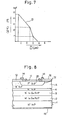
- FIG. 8 shows the layer configuration of the APD
- layer configuration in accordance with this first embodiment resembles fairly closely the layer configuration in accordance with the second general embodiment.
- the major difference resides in the fact that the p-n junction is not stepped shape but has inclined side parts which surround the light sensitive region.
- the p-n junction is in the neighbourhood of the interface between the middle layer and the active layer.
- the p -InP region 20 in Figure 8 is not surrounded by a shallow guard ring region but rather has or is surrounded by gradually inclined sides.
- the principle whereby the guard ring effect is realised is that the combination of such a p-n junction havinglgradually inclined side and the middle layer 4 interleaved between the active layer 5 and the light absorbing layer 3 causes the breakdown voltage to be higher for a point remote from the edge of the side and the bottom of the p-n junction, thereby allowying the side of the p-n junction to act as a guard ring.
- the various parameters for substrate 1 buffer layer 2, the light absorbing layer 3 and active layer 5 are identical to those of the APD described above in connection with Figures 1 to 5.
- the n-InP middle layer 4 has a thickness of 1 micrometer and an impurity concentration of 1 x 10 16 /cm 3 .
- the depth of the p -InP region 20 is 1.5 micrometers.
- the other parameters, including those relating to the Si0 2 anti-reflection coating 11, the Si0 2 insulator film 12, the anode 13, and the cathode 14, are identical to those of the APD described in connection with Figures 1 to 5.
- the gradually inclined region 21 shown in Figure 8 may be formed, for example, by beryllium ion implantation.
- the graph of Figure 9 illustrates the distribution of breakdown voltage along the top surface of the APD.
- an APD as illustrated in Figure 8 in accordance with the first general embodiment of this invention, is operative from a practical point of view. Furthermore, the following additional advantages are provided :-
- an APD in accordance with the first general embodiment of this invention also provides for a reduced magnitude of dark current and lesser excess noise.
- An APD of a form which is a modification of that illustrated in Figure 8 may be provided.
- a low concentration p-type guard ring region is associated with the periphery of the light sensitive region, to provide the guard ring effect.
- Such a low concentration guard ring region may be formed by, for example, ion implantation of a p-type impurity, for example beryllium.
- an APD in accordance with the third general embodiment of the present invention will now be described.
- Such an APD offers the required reduction in dark current and excess noise e.g. tunnel current and can provide the required pronounced difference in breakdown voltages.
- an APD in accordance with the third general embodiment of the present invention has a simpler layer configuration which can be produced by a simpler method which is subject to a lesser number of parameters requiring critical regulation.
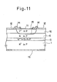
- liquid phase epitaxy is employed to grow an InP surface layer 16 having a thickness of approximately 4 to 5 micrometers and containing one or more n-type impurities to a concentration of approximately 1 x 10 15 /cm 3 on an In p active layer 5 having a thickness of approximately 4 to 5 micrometers and containing one or more n-type impurities in a concentration of approximately 5 x 1 0 15 /c m 3 on an In x Ga 1-x As y P 1-y light absorbing layer 3 having a thickness of approximately 2 micrometers and containing one or more n-type impurities in a concentration of approximately 5 x 10 15 /c m 3 on an InP substrate 1 containing one or more n-type impurities in a concentration of approximately 10 18 /cm 3 .
- one or more p-type impurities are supplied to compensate the n-type impurities inherently contained in the source.
- a chemical vapour deposition process is employed for producing a thin Si0 2 layer 17 on the InP surface layer 16, before a photolithography process is employed to remove the layer 17 from an area corresponding to a light window for the purpose of producing a diffusion mask.
- one or more p-type impurities are diffused into the wafer in a concentration of approximately 10 18 /cm 3 employing the layer 17 as a mask to produce a p-n junction 18 in the neighbourhood of the interface between the n-InP surface layer 16 and the n-InP active layer 5 , or at a deeper level.
- Si0 2 film 11 is produced on the light window to act as an anti- reflectioncoating, and a third Si0 2 film 12 is produced on the guard ring region and on the region surrounding the guard ring region.
- Such films 11 and 12 are separated from one another to leave an area therebetween on which an anode can be produced.
- an anode 14 is produced on the surface layer 16 around the light window or the anti-reflection coating 11, within the film 12, and the cathode 15 is produced on the rear surface of the wafer.
- the bottom of the p-n junction which is horizontal , is located in the active layer 5, From its bottom in the active layer 5 the p-n junction rises through the interface between the active layer 5 and the surface layer 16 and through the surface layer 16.
- the p-n junction may be said to be well-shaped.
- the sides of the p-n junction rising from its bottom may rise abruptly or substantially vertically through the surface layer 16.
- An APD as illustrated in Figure 11, in accordance with the third general embodiment of the present invention, can offer a simple layer configuration as illustrated.
- a light sensitive region is provided which is separated from other regions of the active layer by a p-n junction having a gradually inclined side thereof surrounding the light sensitive region.
- a light sensitive region is separated from other regions of the active layer by a step shaped p-n junction having a deep area which faces the light sensitive region and shallow area which continuously extends, passing through an abruptly vertical side, from the deep area to surround the deep area.
- a light sensitive region is separated from other regions of the surface layer and the active layer by a well shaped p-n junction of which the bottom is located in the active layer.
- the inclined side of the p-n as junction is so curved, gradually curved, / to avoid small radiuses of curvature and sharply curving features.
- the present invention provides an avalanche photodiode comprising:-
- tunnel current is reduced in an APD embodying the present invention as compared with previous APD's.
- An embodiment of the present invention provides an avalanche photodiode,sensitive to light in the wavelength range 1.2 to 1.65 micrometers,which has a light absorbing layer, a middle layer and an active layer grown on a substrate in that order. All the layers contain impurities of the same conductivity type but impurity concentration is higher in the middle layer than in either the light absorbing layer or the active layer.
- a p-n junction having a flat bottom and either a gradually inclined side or a step shaped side is produced in the active layer, whereby the breakdown voltage is less in the area facing the flat bottom of the p-n junction than in the area facing such a side as has the aforementioned irregular shape, resultantly allowing the side to act as a guard ring without a large amount of tunnel current flowing through the light absorbing layer in response to the intensity of electric field.
- a further embodiment of this invention provides an avalanche photodiode with a light absorbing layer, an active layer and a surface layer, grown in this order, having a well shaped p-n junction which penetrates the interface between the surface layer and the active layer to spread along that interface in the active layer. Since impurity concentration in the surface layer is extremely marginal, performance similar to that mentioned above is realized.
Landscapes
- Light Receiving Elements (AREA)
Abstract
Description
- The present invention relates to avalanche photodiodes (hereinafter referred to as APD's).
- An APD is a type of photodiode which can offer various performance advantages, such as higher grade avalanche gain, sensitivity and response time and lower values of dark-current and noise, as compared with other types. These advantages arise from an avalanche breakdown phenomenon which occurs at a p-n junction which is arranged in a multiplication layer in the APD which has a reverse bias applied thereto when the APD is in use to cause the avalanche multiplication of a current of electrons and/or holes generated in a light absorbing region of the device which is exposed to receive light arriving at that region.
- For such advantages to be realised, it must be provided that avalanche. breakdown occurs exclusively and uniformly in a central region of the diode where light is absorbed. Therefore, APD's require some means effective to limit breakdown to a central region of the above mentioned p-n junction.
- The wavelength of light to which an APD is sensitive is determined by the band gap Eg of the material of which the light absorbing layer of the APD is made. In order to produce an APD sensitive to longer wavelength light, a combination of layers of semiconductor, one of which has a relatively small band gap Eg and functions as a light absorbing layer and the other of which has a relatively large band gap Eg and functions as a multiplication layer, is convenient. For the production of an APD sensitive to light in the wavelength range 1.2 to 1.65 micrometers, a combination of InxGa1-xAs1-yPy and InP, or a combination of GaSb and GaxAl1-xSb is preferably employed.
- Multilayered APD's employing the above mentioned group III-V compound or alloy semiconductors have been proposed which have a so-called self guard ring layer configuration,,,in which a p-n junction is formed for the purpose of avalanche multiplication slightly above the heterojunction between the light absorbing layer, of InxGa1-xAs, InxGa1-xAs1-yPy or the like, and the multiplicationlayer, of InP or the like, whereby the intensity of electric field in the light absorbing layer is larger in the central region of the diode, or in a light absorbing region, than in other regions thereof, or in regions not exposed to light, causing the breakdown voltage of the p-n junction to become less in the central region of the diode which is exposed to light than in regions which are not exposed to light. This provides the guard ring effect. The function of this so-called self guard ring configuration is based upon the characteristic that the band gap Eg of the group III-V compound or alloy semiconductor of which the light absorbing layer is made is less than the band gap Eg of t.he group III-V compound or alloy semiconductor of which the multiplication or active layer is made and that the breakdown voltage is less for the former than for the latter. It has been determined that this so-called self guard ring configuration provides an excellent guard ring effect.
- The inventors of the present invention have, however, discovered that APD's having the so-called self guard ring configuration have a drawback as described below.
- Since the intensity of electric field is necessarily high in the light absorbing layer,'a tunnel current or a current component resulting from carriers directly excited by the high intensity of electric field has inevitably occur red in the light absorbing layer, giving rise to various adverse effects, e.g. relatively large amounts of dark current, noise or the like. It is well-known that the magnitude of tunnel effect is larger for a substance having a lesser band gap Eg, such as group III-V compound or alloy semiconductors, e.g. InxGa1-xAs1-yPy or GaSb and the like.
- Now, it is well-known that the fundamental absorption edge ( is determined by the equality ) = hc/Eg, and in view of the fact that the signal transmission loss in an optical fibre is less for longer wavelength light it is therefore preferable to use APD's sensitive to longer wavelength light, having thus a light absorbing layer made of a material having a lesser band gap Eg, in fibre optics communications.
- For this reason, the above described drawback arising from the relatively large amount of tunnel current which is inherent in APD's having the so-called self guard ring configuration is of serious practical significance.
- The present invention is concerned with the provision of APD's which do not suffer from the above-mentioned drawback. Embodiments of the present invention can also afford various other advantages.
- The present invention provides a multilayer APD having a guard ring configuration which can readily realise an efficient guard ring effect without suffering the above- described tunnel current problem, as a result providing for the realisation of higher grades of avalanche-gain, sensitivity and response time and lower values of dark-current and noise.
- The present invention provides for an APD of a planar type.
- For example, the present invention can provide an APD sensitive to light in a wavelength range 1.2 to 1.65 micrometers, which is provided with a light absorbing layer made of a group III-V compound or alloy semiconductor, for example InxGa1-xAs1-yPy or GaSb, and with a multiplication or active layer made of another group III-V alloy or compound semiconductor, for example InP or GaxAl1-xSb, having a larger band gap Eg than that of the material of the light absorbing layer.
- This invention can further provide a planar type APD having a more efficient guard ring effect, realising a more pronounced difference in breakdown voltage between the central region of the p-n junction and other regions thereof.
- This invention can also provide a planar type APD having a simple layer configuration, in which the number of essential design parameters is reduced from three to two, thereby allowing considerable freedom for design and production of the APD.
- This invention has an embodiment which provides an APD having
- (a) a light absorbing layer made of a group III-V compound or alloy semiconductor, such as InxGa1-xAsyP1-y, GaSb, or the like, containing one or some impurities of one conductivity type preferably in a relatively low concentration,
- (b) a relatively thin layer (hereinafter referred to as a middle layer) for example of a thickness of 0.5 micrometers or less, made of a material which allows lattice matching between itself and the light absorbing layer and which has a larger band gap Eg than that of the semiconductor forming the light absorbing layer, preferably a group III-V compound or alloy semiconductor, such as InP where the light absorbing layer is of In xGa1-xAs1-yPy or Ga Al Sb where the light absorbing layer is of GaSb, containing one or some impurities of a conductivity type the same as that of the light absorbing layer preferably in a concentration the same as or greater than that of the light absorbing layer, the middle layer being grown on the light absorbing layer, and
- (c) a multiplication or active layer, of a relatively large thickness, for example 4 to 5 micrometers, of a material which allows lattice matching between itself and the middle layer and which has a larger band gap Eg than that of the semiconductor forming the light absorbing layer, preferably a group III-V compound or alloy semiconductor substantially identical to that of the middle layer, primarily containing one or some impurities of a conductivity type the same as that of the middle layer in a concentration which.is less than, e.g. several tenths of , that of the middle layer, the active layer being grown on the middle layer,
- The position of the p-n junction (e.g. the flat bottom of the p-n junction, in the light sensitive region) is in the neighbourhood of the interface between the middle layer and the active layer.
- Such an APD embodying the present invention has the following attributes:-
- 1. The breakdown voltage is higher for the gradually inclined sides of the p-n junction than for the flat bottom of the p-n junction, as a result allowing preferential breakdown for the region exposed to light (the light sensitive region) when the device is in use. As a result, an effective guard ring effect is provided.
- 2. The middle layer, containing impurities in a relatively high concentration (for example as compared with the active layer), considerably decreases the intensity of electric field in the light absorbing layer, as a result decreasing the magnitude of tunnel current to a value which is insignificant in comparison with the other components of dark-current.
- 3. The relatively low magnitude of impurity concentration contained in the active layer (for example as compared with the middle layer) decreases the intensity of electric field, even at a time when a breakdown occurs, as a result increasing the ratio of ionisation coefficient of electrons and holes.
- 4. The APD can be of a planar type.
- It is noted that the above proposed configuration of an embodiment of the present invention has become possible because the inventors of this invention have discovered that a InP epitaxial layer containing n-impurity in a concentration as low as 1 x 10¹⁵/cm3 can be grown by employing an unintentional doping liquid phase epitaxial process concurrently accompanied by conpensation for p-type impurities.
- This invention has a second embodiment which is an APD having :-
- (a) a light absorbing layer, which may be formed as described above with connection with the first embodiment of this invention,
- (b) a middle layer, which may be formed as described above for the first embodiment of this invention, and
- (c) an active layer , which may be formed substantially as described above for the first embodiment of this invention, but having a relatively deep region therein, forming the light sensitive region, which contains one or some impurities of a conductivity type different from that of the light absorbing, middle and active layers, in a high concentration, e.g. approximately 10 /cm , and the active layer also having a relatively shallow region, forming a guard ring surrounding the light sensitive region, which contains one or some impurities of conductivity type the same as that of the light sensitive region in a high concentration the same as that of the light sensitive region, the light sensitive region and the guard ring region being separated from other regions of the active layer by a p-n junction which is stepped, having a relatively deep part in relation to the light sensitive region, and a relatively shallow part in relation to the guard region, with an abrupt transition between the deep and shallow parts. The p-n junction may have abruptly vertical sides which surround the light sensitive region and join together the junction in respect of the light sensitive region and the junction in respect of the shallow flat guard ring region.
- Such an APD has the attribute that a more pronounced difference in breakdown voltages between the light sensitive region and the guard ring region is achieved, resulting in a more reliable guard ring effect.
- The present invention has a third embodiment which is an APD having :-
- (a) a light absorbing layer, which may be as described above in connection with the first embodiment of this invention,
- (b) an active layer of a relatively large thickness, e.g. 2 to 3 micrometers, made of a material which allows lattice matching between itself and the light absorbing layer and which has a larger band gap Eg than that of the semiconductor forming the light absorbing layer, preferably a group III-V compound or alloy semiconductor, such as InP in a case in which the light absorbing layer is of InxGa1-xAsyP1-y, or Gax All Sb in a case in which the light absorbing layer is of GaSb, primarily containing one or some impurities of a conductivity type identical to that of the light absorbing layer in a concentration the same as or greater than that of the light absorbing layer, the active layer being grown on the light absorbing layer and,
- (c) a surface layer made of a material which allows lattice matching between itself and the active layer and has a larger band gap Eg than that of the semiconductor forming the light absorbing layer, preferably a group III-V compound or alloy semiconductor substantially identical to that of the active layer, primarily containing one or some impurities of a conductivity type the same as that of the light absorbing layer in a concentration which is less than, for example several tenths of, that of the active layer, or less, e.g. 1 x 10 /cm , the surface layer and an upper portion of the active layer having formed therein a region constituting a light sensitive region which contains one or some impurities of a conductivity type different from that of the impurities of the active and light absorbing layers in a high concentration, e.g. approximately 1018/cm3, and the light sensitive region being separated from the other regions of the active layer and the surface layer by a p-n junction which extends down through the surface layer and into the active layer. The p-n junction may have a horizontal part in the active layer surrounded by parts which rapidly rise through the surface layer. The sidesof the p-n junction may rise substantially vertically through the surface layer.
- Such an APD has the following attributes.
- For the production of APD's in accordance with the first and second embodiments of this invention, precise regulation is required of three independent parameters - (a) carrier concentration in the active layer, (b) carrier concentration in the middle layer, and (c) the distance between the p-n junction the the interface between the active layer and the middle layer. Further, attention must be paid to the curvature of the p-n junction in order to prevent a high intensity electric field occurring at curved portions of the p-n junction. In an APD in accordance with the third embodiment of this invention, the parameters which must be regulated are reduced to two and the layer configuration is simplified, thereby allowing a considerable latitude for design and production.
- It will be understood that the ranges of layer thicknesses above are indicated only by way of example. Devices embodying the present invention may be constructed with layer thicknesses different from those mentioned above, as will be seen from the descriptions below in which reference is made to the drawings. Values of impurity concentration mentioned above are likewise by way of
- Reference is made, by way of example, to the accompanying drawings, in which:-
- Figures 1 to 5 are respective sectional views for assistance in explanation of the structure of an APD embodying the present invention, the respective Figures showing the APD at various stages in its production, Figure 5 showing the finished APD,
- Figure 6 is a graph illustrating electric field intensity versus distance from a p-n junction formed in the light sensitive region of a APD having a layer configuration as illustrated in Figure 5,
- Figure 7 is a graph showing electric field intensity versus distance from a p-n junction in a guard ring region of an APD having a layer configuration as shown in Figure 5,
- Figure 8 is a schematic sectional view illustrating the layer configuration of an APD in accordance with another embodiment of the present invention,
- Figure 9 is a graph illustrating breakdown voltage versus horizontal position in an APD having a layer configuration as shown in Figure 8, and
- Figures 10 and 11 are respective sectional views for assistance in explanation of the structure of an APD in accordance with another embodiment of the present invention, Figure 10 showing the APD at an intermediate stage in its manufacture, and Figure 11 showing the finished APD.
- Three broad embodiments of the present invention are presented above. An APD in accordance with the second broad embodiment as mentioned above will be described first herebelow, followed by descriptions of APD's in accordance with the first and third broad embodiments , respectively.
- For simplicity, the descriptions given herebelow of APD's in accordance with the first and second broad embodiments of this invention will be provided in relation to APD's having an n-InP substrate, an n-InP buffer ,. an n-InxGa1-xAsyP1-y light absorbing layer,an n-InP middle layer, and an n-InP active layer, a limited, deep, region of the active layer being doped with a p-type impurity to form a light sensitive region which is surrounded by a shallow p-doped region forming a guard ring. Production of the layers of the APD's will be assumed to be effected by continuously growing the layers employing liquid phase epitaxy in one process. Of course, lattice matching is required between adjacent layers.
- Referring to Figure 1, a first step in the production of an APD in accordance with the first general embodiment of the present invention , is the growth of an n-
InP buffer layer 2 of a thickness of several micrometers and an n-impurity concentration of approximately 1016/cm3 on an n-InPsingle crystal substrate 1 with an n-impurity concentration of approximately 10 /cm . The purpose of this step is simply to provide improved crystal conditions or surface conditions, and this step is not essential to the present invention but preferable. Technical significance of the above-mentioned values of impurity concentration and layer thickness are merely exemplary. - A second step is to grow a

absorbing layer 3 of a thickness of 2 micrometers or more with an n-impurity concentration of 5 x 10¹⁵ to 1 x 10¹⁶/cm3 on thesubstrate 1, or preferably on thebuffer layer 2. - A third step is to grow an n-InP
middle layer 4 of a thickness of 0.5 micrometers or less with an n-impurity concentration the same as or greater than that of thelight absorbing layer 3, possibly more than 2 x 10 16/cm 3, on thelight absorbing layer 3. - A fourth step is to grow an n-InP
active layer 5 of a thickness of approximately 2.5 micrometers and with an n-impurity concentration which is tenths, of that of the middle layer, or less, preferable 5 x 10 to 1 x 10¹⁶/cm3, on themiddle layer 4. - A fifth step is to grow an n-InxGa1-xAs layer (hereinafter referred to as a mask layer) 6 on the
active layer 5. Thismask layer 6 is intended to act as a mask during subsequent etching and dif-fusion steps for the final purpose of producing a step shaped p-n junction as shown in Figure 3. Therefore, an arbitrary magnitude of n-type impurity concentration is allowed, save that it should not be such as to give rise to any adverse effect in relation to the impurity concentration of theactive layer 5 during subsequent diffusion processes. As described earlier, the foregoing five steps are carried out in one process employing liquid phase epitaxy. - A sixth step is to produce a resist
photomask 7, resistant to sulphuric acid based solvents, on themask 6 except for a part thereof corresponding to the light sensitive region. - Referring to Figure 2, a seventh step is selectively to remove the portion of the
mask layer 6 unmasked by the resistphotomask 7. A convenient process for accomplishing this step is to soak the wafer in a solution containing three portions of sulphuric acid, one portion of hydrogen peroxide and one portion of water, because this solution does not dissolve InP , albeit it does dissive InxGa1-xAs. - An eighth step is to remove the resist
photomask 7, before a silicon dioxide layer is grown on the wafer, more specifically on themask layer 6 and partly on theactive layer 5. Photolithography is employed to remove parts of the silicon dioxide layer from the regions corresponding to the light sensitive region and a guard ring region, in order to produce a mask 9 having anopening 8 on the light sensitive region and the guard ring region. - Referring to Figure 3, a ninth step is to employ an impurity diffusion process to introduce a p-type impurity into an
upper portion 10 of theactive layer 5 to a high concentration such as 1018/cm3. Due to the stepped shape of the double-layered mask 9 and 6, a p-n junction itself of a stepped shape is produced. In other words, the depth of the p-n junction is much larger where the light sensitive region is confronted than in the guard ring region. This impurity diffusion process can be carried out at a temperature of 5000C employing CdP2 as the impurity source. In this embodiment of the present invention the p-n junction comprises a relatively deep part, produced at a depth of 1.5 micrometers, in the light sensitive region and a relatively shallow part which extends around the deep part and is produced at a depth of 0.5 micrometers in the area corresponding to the guard ring region . - Therefore, the deep part of the p-n junction is located 1 micrometer above the interface between the
active layer 5 and themiddle layer 4, and the relatively shallow part providing the guard ring is located 2 micrometers above the interface between theactive layer 5 and themiddle layer 4. A two hour period was required for the diffusion to form the stepped shape p-n junction. - An alternative process, as described below, can be employed for production of the stepped shape p-n junction. In this alternative process, a recess is produced by means of an etching process applied to an area corresponding to the light sensitive region of the top surface of the n-InP
active layer 5, rather than producing a mask made of SiO2 layer 9 and the n-InxGa1-xAslayer 6 as described above, before a p-type impurity is diffused in. This has the advantage of simplicity and in reduction in the number of heating processes required. - Referring to Figure 4, a tenth step is to remove the Si02 layer 9 and the n-InxGa1-xAs
layer 6 both of which were employed in combination as a mask in the previous step, before producing an Si02 film 11 on the light sensitive region , whichfilm 11 is to act as an anti-reflection coating, and another Si02 film 12 on the guard ring region and the region surrounding the guard ring region, whichfilm 12 is to act as an insulator.Such films area 13 on which an anode of the APD is to be produced. between thefilms layer 6 can be readily carried out by soaking the wafer respectively in a solution containing fluoric acid and ammonium fluoride and a sulphuric acid based solvent. Chemical vapour deposition and photolithography are in combination employed for production of thefilms - Referring to Figure 5, the eleventh step is to produce an
anode 14 and acathode 15 respectively on thearea 13 and on the bottom surface of the wafer. In this case, the anode and the cathode are produced by means of the vacuum evaporation of AuZn and AuGe respectively. - When such an APD is operated, the APD has applied thereto a negative voltage and a positive voltage respectively at its anode and cathode. Since the application of these voltages reverse biases the p-n junction produced in an APD whose layer configuration is as shown by way of example in Figure 5, a depletion layer extends across the p-n junction.
- Within a depletion layer, the differential of intensity of electric field versus the distance from a p-n junction is proportional to the impurity concentration of the corresponding region.
- Therefore, in the case of a layer configuration as shown in Figure 5, the extent of the depletion layer is quite marginal towards the p side of the p-n junction, the depletion layer tends to extend far into the
middle layer 4 and thelight absorbing layer 3. - Since the p-n junction is step shaped and the impurity concentration is non-uniform in the direction of depth, the distance to which the depletion layer extends is different for the light sensitive region and for the region corresponding to the guard ring region. On the assumption that the n-type impurity concentration is 8 x 10¹⁵/cm3 for the
active layer 5 and for thelight absorbing layer 3 and is 2 x 10¹⁶/cm3 for themiddle layer 4, the relationships between the intensity of electric field and depth from the wafer surface are as shown in the graphs of Figures 6 and 7. - The polygonal line A in the graph of Figure 6 illustrates the position in which a breakdown occurs in the light sensitive-region, whilst the polygonal line B in the graph of Figure 7 illustrates the position in which a breakdown occurs in the guard ring region .
- From the graph of Figure 6 it will be seen that the intensities of electric field at the p-n junction, at the interface between the
active layer 5 and themiddle layer 4, and at the interface between themiddle layer 4 and thelight absorbing layer 3,are respectively 4.73 x 10⁵V/cm, 3.56 x 10⁵V/cm and 2.10 x 10 5 V/cm. In relation to the graph of Figure 7 it will be seen that the corresponding intensities of electric field are 4.73 x 10⁵V/cm, 2.39 x 10⁵V/cm and 0.93 x 10⁵V/cm respectively. - In each of the graphs of Figures 6 and 7, the area surrounded by the solid line, A or B, and the X-axis relates to breakdown voltage. Figure 6 shows that the breakdown voltage in the light sensitive region is 75.6 V. Figure 7 shows that the breakdown voltage in the area facing the guard ring is 90.2 V. Since a fairly large difference, specifically 14.6 V, is manifest between the breakdown voltages for the light sensitive region and for the area facing the guard ring, an APD in accordance with an embodiment of this invention allows breakdown to occur only in the light sensitive region, by virtue of the pronounced difference in breakdown voltages between the light sensitive region and the area facing the guard ring.
- As described above, the
middle layer 4 interleaved between theactive layer 5 and thelight absorbing layer 3 has a relatively large band gap and contains impurities in a relatively high concentration. Thismiddle layer 4 causes a large decrease in electric field intensity, thereby decreasing the intensity of electric field in thelight absorbing layer 3. This causes a reduction in the amount of tunnel current which may flow across this layer. - In an embodiment of the present invention in which the intensities of electric field are as described above, a maximum tunnel current accompanying a breakdown occurring in response to exposure to light having a wavelength of 1.35micrometers, or the fundamental absorption edge of InxGa1-xAsyP1-y, , is 8 x 10-14A, on the assumption that the diameter of a light window is 100 micrometers. Corresponding amount in a case in which the APD is exposed to light having a wavelength of 1.65 micrometers is 3 x 10 A. Since the magnitude of tunnel current is much less than the magnitudes of dark current caused by other parameters, the magnitude of the overall dark current is satisfactorily decreased.
- It is well known that the excess noise coefficient decreases in accordance with the ratio of ionisation factors of holes and electrons. On the other hand, it is also well known that the ionisation factors of holes and electrons increase in accordance with the inverse of electric field intensity. In the described embodiment of the present invention, therefore, the impurity concentration of the
active layer 5 is decreased in order to decrease the intensity of electric field in the event of breakdown and, therefore, to increase the ratio of ionisation factors of holes and electrons. Thereby, the magnitude of excess noise is decreased. - From Figure 5, it will be readily appreciated that an APD in accordance with this embodiment of the present invention is of the planar type.
- As described above, an APD embodying the present invention has a structure such as substantially to eliminate the above-mentioned tunnel current problem and which also provides a more pronounced difference in breakdown voltages.
- In such an embodiment of the present invention the p-n junction has a stepped configuration, a relatively shallow part of the p-n junction surrounding a relatively deep part of the p-n junction, with an abrupt transition between the relatively deep and relatively shallow parts. the abrupt transitional part of the p-n junction may conform to a substantially vertical surface.
- With reference to Figures 8 and 9 of the accompanying drawings , an APD in accordance with the first general embodiment of the present invention will now be described. As indicated in Figure 8, which shows the layer configuration of the APD, layer configuration in accordance with this first embodiment resembles fairly closely the layer configuration in accordance with the second general embodiment. The major difference resides in the fact that the p-n junction is not stepped shape but has inclined side parts which surround the light sensitive region. The p-n junction is in the neighbourhood of the interface between the middle layer and the active layer.
- In other words, the p -InP region 20 in Figure 8 is not surrounded by a shallow guard ring region but rather has or is surrounded by gradually inclined sides.
- In this case, the principle whereby the guard ring effect is realised is that the combination of such a p-n junction havinglgradually inclined side and the
middle layer 4 interleaved between theactive layer 5 and thelight absorbing layer 3 causes the breakdown voltage to be higher for a point remote from the edge of the side and the bottom of the p-n junction, thereby allowying the side of the p-n junction to act as a guard ring. - Specifically referring to Figure 8, the various parameters for
substrate 1buffer layer 2, thelight absorbing layer 3 andactive layer 5 are identical to those of the APD described above in connection with Figures 1 to 5. - The n-InP
middle layer 4 has a thickness of 1 micrometer and an impurity concentration of 1 x 10 16 /cm 3. The depth of the p -InP region 20 is 1.5 micrometers. The other parameters, including those relating to the Si02 anti-reflection coating 11, the Si02 insulator film 12, theanode 13, and thecathode 14, are identical to those of the APD described in connection with Figures 1 to 5. The graduallyinclined region 21 shown in Figure 8 may be formed, for example, by beryllium ion implantation. - The graph of Figure 9 illustrates the distribution of breakdown voltage along the top surface of the APD. The breakdown voltage 66.5 V within the light sensitive region, gradually increasing to 99.4 V at the external edge of the p-n junction, thereby realising a guard ring effect.
- Albeit that in this case a less pronounced difference between breakdown voltage in the region facing the light window and in the guard ring region is realised than in an APD in accordance with the first general embodiment of the present invention, an APD as illustrated in Figure 8, in accordance with the first general embodiment of this invention, is operative from a practical point of view. Furthermore, the following additional advantages are provided :-
- 1. No mask is required for the production of a shallow part of the p+-InP region, because the APD has no such shallow part.
- 2. None of the adverse effects which can be caused by the use of a stepped shape p-n junction occur. In other words, with a step shape p-n junction, parts of the junction have only a small radius of curvature, or curve rather sharply, and a reduction in breakdown voltage is manifest at such sharp curves. With the configuration as illustrated in Figure 8 such adverse effects are not observed.
- Of course, an APD in accordance with the first general embodiment of this invention, for example as illustrated in Figure 8, also provides for a reduced magnitude of dark current and lesser excess noise.
- An APD of a form which is a modification of that illustrated in Figure 8 may be provided. In this modified form a low concentration p-type guard ring region is associated with the periphery of the light sensitive region, to provide the guard ring effect. Such a low concentration guard ring region may be formed by, for example, ion implantation of a p-type impurity, for example beryllium.
- With reference to Figures 10 and 11, an APD in accordance with the third general embodiment of the present invention will now be described. Such an APD offers the required reduction in dark current and excess noise e.g. tunnel current and can provide the required pronounced difference in breakdown voltages. In addition, an APD in accordance with the third general embodiment of the present invention has a simpler layer configuration which can be produced by a simpler method which is subject to a lesser number of parameters requiring critical regulation.
- With reference to Figure 10, liquid phase epitaxy is employed to grow an
InP surface layer 16 having a thickness of approximately 4 to 5 micrometers and containing one or more n-type impurities to a concentration of approximately 1 x 10¹⁵/cm3 on an Inpactive layer 5 having a thickness of approximately 4 to 5 micrometers and containing one or more n-type impurities in a concentration of approximately 5 x 10 15/cm 3 on an InxGa1-x AsyP1-ylight absorbing layer 3 having a thickness of approximately 2 micrometers and containing one or more n-type impurities in a concentration of approximately 5 x 10 15 /cm3 on anInP substrate 1 containing one or more n-type impurities in a concentration of approximately 1018/cm3. - Over the period in which the
InP surface layer 16 is grown, primarily based on the unintentional doping basis , one or more p-type impurities are supplied to compensate the n-type impurities inherently contained in the source. - A chemical vapour deposition process is employed for producing a thin Si02 layer 17 on the
InP surface layer 16, before a photolithography process is employed to remove thelayer 17 from an area corresponding to a light window for the purpose of producing a diffusion mask. - With reference to Figure 11, one or more p-type impurities are diffused into the wafer in a concentration of approximately 1018/cm3 employing the
layer 17 as a mask to produce ap-n junction 18 in the neighbourhood of the interface between the n-InP surface layer 16 and the n-InPactive layer 5 , or at a deeper level. - After the
layer 17 is removed, another Si02 film 11 is produced on the light window to act as an anti- reflectioncoating, and a third Si02 film 12 is produced on the guard ring region and on the region surrounding the guard ring region.Such films - Thereafter an
anode 14 is produced on thesurface layer 16 around the light window or theanti-reflection coating 11, within thefilm 12, and thecathode 15 is produced on the rear surface of the wafer. - The major difference between the layer configurations of the APD illustrated in Figure 11 , in accordance with the third general embodiment of the present invention, and APD's in accordance with the first and second general embodiments of the present invention, is that no middle layer is provided and the location of the p-n junction is somewhat more freely determinable , with the result that the parameters needing careful control in production are virtually limited to the control of the concentration of the active layer, albeit that the location of the p-n junction is of considerable physical significance.
- In the APD of Figure 11 the bottom of the p-n junction, which is horizontal , is located in the
active layer 5, From its bottom in theactive layer 5 the p-n junction rises through the interface between theactive layer 5 and thesurface layer 16 and through thesurface layer 16. Thus, the p-n junction may be said to be well-shaped. The sides of the p-n junction rising from its bottom may rise abruptly or substantially vertically through thesurface layer 16. - An APD as illustrated in Figure 11, in accordance with the third general embodiment of the present invention, can offer a simple layer configuration as illustrated.
- Thus, in one embodiment of the present invention in which a middle layer is provided between a light absorbing layer and an active layer, a light sensitive region is provided which is separated from other regions of the active layer by a p-n junction having a gradually inclined side thereof surrounding the light sensitive region.
- In another embodiment of the present invention a light sensitive region is separated from other regions of the active layer by a step shaped p-n junction having a deep area which faces the light sensitive region and shallow area which continuously extends, passing through an abruptly vertical side, from the deep area to surround the deep area.
- In another embodiment of the-present invention, in which the active layer is formed on the light absorbing layer, and a surface layer is formed on the active layer, a light sensitive region is separated from other regions of the surface layer and the active layer by a well shaped p-n junction of which the bottom is located in the active layer.
- In the embodiment of the present invention in which a light sensitive region is separated from other regions of the active layer by a p-n junction having a gradually inclined side, the inclined side of the p-n as junction is so curved, gradually curved,/to avoid small radiuses of curvature and sharply curving features.
- The present invention provides an avalanche photodiode comprising:-
- a light absorbing layer, of a semiconductor containing at least one impurity of one conductivity type,
- an active layer, of a semiconductor having a larger band gap than that of the semiconductor of the light absorbing layer, containing at least one impurtiy of the said one conductivity type, and a further layer, between the light absorbing layer and the active layer, or upon the active layer with the active layer upon the light absorbing layer, of a semiconductor having a larger band gap than that of the semiconductor of the light absorbing layer, containing at least one impurity of the said one conductivity type,
- the photodiode having a p-n junction at least a part of which is located in the active layer, to provide a light sensitive region, and other parts of which are more remote than the said part from the light absorbing layer.
- By the disposition of different parts of the p-n junction and by the layer configuration provided in accordance with the present invention tunnel current is reduced in an APD embodying the present invention as compared with previous APD's.
- An embodiment of the present invention provides an avalanche photodiode,sensitive to light in the wavelength range 1.2 to 1.65 micrometers,which has a light absorbing layer, a middle layer and an active layer grown on a substrate in that order. All the layers contain impurities of the same conductivity type but impurity concentration is higher in the middle layer than in either the light absorbing layer or the active layer. A p-n junction having a flat bottom and either a gradually inclined side or a step shaped side is produced in the active layer, whereby the breakdown voltage is less in the area facing the flat bottom of the p-n junction than in the area facing such a side as has the aforementioned irregular shape, resultantly allowing the side to act as a guard ring without a large amount of tunnel current flowing through the light absorbing layer in response to the intensity of electric field.
- A further embodiment of this invention provides an avalanche photodiode with a light absorbing layer, an active layer and a surface layer, grown in this order, having a well shaped p-n junction which penetrates the interface between the surface layer and the active layer to spread along that interface in the active layer. Since impurity concentration in the surface layer is extremely marginal, performance similar to that mentioned above is realized.
the active layer having therein a light sensitive region which contains one or some impurities of a conductivity type different from that of the impurities of the middle layer in a high concentration, e.g. approximately 1018/cm3, that light sensitive region being separated from other regions of the active layer by a p-n junction having gradually inclined sides surrounding the light sensitive region.
Claims (10)
Applications Claiming Priority (2)
| Application Number | Priority Date | Filing Date | Title |
|---|---|---|---|
| JP55169889A JPS5793585A (en) | 1980-12-02 | 1980-12-02 | Semiconductor photoreceiving element |
| JP169889/80 | 1980-12-02 |
Related Child Applications (1)
| Application Number | Title | Priority Date | Filing Date |
|---|---|---|---|
| EP85101755.8 Division-Into | 1981-12-01 |
Publications (3)
| Publication Number | Publication Date |
|---|---|
| EP0053513A2 true EP0053513A2 (en) | 1982-06-09 |
| EP0053513A3 EP0053513A3 (en) | 1983-01-19 |
| EP0053513B1 EP0053513B1 (en) | 1987-10-28 |
Family
ID=15894830
Family Applications (2)
| Application Number | Title | Priority Date | Filing Date |
|---|---|---|---|
| EP81305658A Expired EP0053513B1 (en) | 1980-12-02 | 1981-12-01 | Avalanche photodiodes |
| EP85101755A Ceased EP0156156A1 (en) | 1980-12-02 | 1981-12-01 | Avalanche photodiodes |
Family Applications After (1)
| Application Number | Title | Priority Date | Filing Date |
|---|---|---|---|
| EP85101755A Ceased EP0156156A1 (en) | 1980-12-02 | 1981-12-01 | Avalanche photodiodes |
Country Status (4)
| Country | Link |
|---|---|
| US (1) | US4481523A (en) |
| EP (2) | EP0053513B1 (en) |
| JP (1) | JPS5793585A (en) |
| DE (1) | DE3176503D1 (en) |
Cited By (10)
| Publication number | Priority date | Publication date | Assignee | Title |
|---|---|---|---|---|
| FR2518817A1 (en) * | 1981-12-23 | 1983-06-24 | Thomson Csf | PHOTODIODE WITH SEPARATE ABSORPTION AND AVALANCHE ZONES |
| EP0159544A1 (en) * | 1984-03-22 | 1985-10-30 | Nec Corporation | Avalanche photodiode and its manufacturing method |
| EP0109855A3 (en) * | 1982-11-19 | 1985-12-04 | Nec Corporation | Photodiode having heterojunction |
| EP0103084A3 (en) * | 1982-07-21 | 1986-03-19 | Siemens Aktiengesellschaft | Method of making a planar heterostructure photodiode |
| EP0150564A3 (en) * | 1983-10-26 | 1986-05-14 | AT&T Corp. | Electronic device comprising a heterojunction |
| EP0163295A3 (en) * | 1984-05-31 | 1986-12-03 | Fujitsu Limited | A semiconductor photodetector and fabrication process for the same |
| EP0163546A3 (en) * | 1984-05-31 | 1987-12-09 | Fujitsu Limited | Process for fabricating an avalanche photodiode and an avalanche photodiode thus-obtained |
| EP0373752A3 (en) * | 1988-12-14 | 1990-08-16 | Kabushiki Kaisha Toshiba | Semiconductor light detector and method of manufacturing the same |
| US5723877A (en) * | 1989-08-04 | 1998-03-03 | Canon Kabushiki Kaisha | Photoelectric conversion apparatus |
| EP0437633B1 (en) * | 1989-08-04 | 2000-11-02 | Canon Kabushiki Kaisha | Photo-electric converter |
Families Citing this family (43)
| Publication number | Priority date | Publication date | Assignee | Title |
|---|---|---|---|---|
| JPS5854685A (en) * | 1981-09-28 | 1983-03-31 | Kokusai Denshin Denwa Co Ltd <Kdd> | Avalanche photodiode and manufacture thereof |
| KR900000074B1 (en) * | 1981-10-02 | 1990-01-19 | 미쓰다 가쓰시게 | Beam-checking semiconductor apparatus |
| JPS58154276A (en) * | 1982-03-10 | 1983-09-13 | Nippon Telegr & Teleph Corp <Ntt> | Avalanche photo diode |
| JPS5984589A (en) * | 1982-11-08 | 1984-05-16 | Fujitsu Ltd | Semiconductor photodetector |
| US4529996A (en) * | 1983-04-14 | 1985-07-16 | Allied Coporation | Indium phosphide-boron phosphide heterojunction bipolar transistor |
| US4611388A (en) * | 1983-04-14 | 1986-09-16 | Allied Corporation | Method of forming an indium phosphide-boron phosphide heterojunction bipolar transistor |
| US4586066A (en) * | 1984-04-10 | 1986-04-29 | Rca Inc. | Avalanche photodetector |
| CA1228663A (en) * | 1984-04-10 | 1987-10-27 | Paul P. Webb | Photodetector with isolated avalanche region |
| CA1228661A (en) * | 1984-04-10 | 1987-10-27 | Rca Inc. | Avalanche photodetector |
| CA1228662A (en) * | 1984-04-10 | 1987-10-27 | Paul P. Webb | Double mesa avalanche photodetector |
| JPS61172381A (en) * | 1984-12-22 | 1986-08-04 | Fujitsu Ltd | Inp group compound semiconductor device |
| FR2581482B1 (en) * | 1985-05-03 | 1987-07-10 | Labo Electronique Physique | LOW LEAKAGE CURRENT PIN PHOTODIODE |
| US4700209A (en) * | 1985-10-30 | 1987-10-13 | Rca Inc. | Avalanche photodiode and a method of making same |
| JPS62259481A (en) * | 1986-04-15 | 1987-11-11 | Fujitsu Ltd | Semiconductor light receiving device |
| EP0283699B1 (en) * | 1987-03-23 | 1994-06-15 | Hitachi, Ltd. | Photoelectric conversion device |
| CA1280196C (en) * | 1987-07-17 | 1991-02-12 | Paul Perry Webb | Avanlanche photodiode |
| JP2664158B2 (en) * | 1987-08-24 | 1997-10-15 | 株式会社日立製作所 | Method for manufacturing semiconductor light receiving device |
| US4857982A (en) * | 1988-01-06 | 1989-08-15 | University Of Southern California | Avalanche photodiode with floating guard ring |
| US5179430A (en) * | 1988-05-24 | 1993-01-12 | Nec Corporation | Planar type heterojunction avalanche photodiode |
| JPH03270277A (en) * | 1990-03-20 | 1991-12-02 | Fujitsu Ltd | Semiconductor photoreceptor element |
| US6515315B1 (en) * | 1999-08-05 | 2003-02-04 | Jds Uniphase, Corp. | Avalanche photodiode for high-speed applications |
| JP3910817B2 (en) * | 2000-12-19 | 2007-04-25 | ユーディナデバイス株式会社 | Semiconductor photo detector |
| JP4170004B2 (en) * | 2002-03-28 | 2008-10-22 | 日本板硝子株式会社 | Compound semiconductor multilayer structure |
| US7135715B2 (en) * | 2004-01-07 | 2006-11-14 | Cree, Inc. | Co-doping for fermi level control in semi-insulating Group III nitrides |
| JP2006237186A (en) * | 2005-02-24 | 2006-09-07 | Mitsubishi Electric Corp | Semiconductor light receiving element and manufacturing method thereof |
| JP4956944B2 (en) * | 2005-09-12 | 2012-06-20 | 三菱電機株式会社 | Avalanche photodiode |
| US7553734B2 (en) * | 2005-10-17 | 2009-06-30 | Princeton Lightwave, Inc. | Method for forming an avalanche photodiode |
| JP2007129033A (en) * | 2005-11-02 | 2007-05-24 | Nippon Sheet Glass Co Ltd | Avalanche photodiode and manufacturing method thereof |
| JP5015494B2 (en) * | 2006-05-22 | 2012-08-29 | 住友電工デバイス・イノベーション株式会社 | Semiconductor photo detector |
| FR2906082B1 (en) * | 2006-09-18 | 2008-10-31 | Commissariat Energie Atomique | PHOTODIODE AT AVALANCHE |
| JP4520480B2 (en) * | 2007-03-29 | 2010-08-04 | 住友電工デバイス・イノベーション株式会社 | Manufacturing method of light receiving element |
| FR2938374B1 (en) * | 2008-11-10 | 2011-02-11 | Commissariat Energie Atomique | INTERNAL GAIN PHOTODETECTOR AND DETECTOR COMPRISING A MATRIX OF SUCH PHOTODETECTORS |
| JP2010268000A (en) * | 2010-08-11 | 2010-11-25 | Go Foton Holdings Inc | Avalanche photodiode and method of manufacturing the same |
| US9917156B1 (en) | 2016-09-02 | 2018-03-13 | IQE, plc | Nucleation layer for growth of III-nitride structures |
| RU2654386C1 (en) * | 2016-12-27 | 2018-05-17 | Акционерное общество "НПО "Орион" | Method for manufacturing a planar avalanche photodiod |
| CN109841701B (en) * | 2017-11-24 | 2021-09-10 | 比亚迪半导体股份有限公司 | Photodiode and manufacturing process thereof |
| US11322639B2 (en) * | 2020-04-09 | 2022-05-03 | Globalfoundries U.S. Inc. | Avalanche photodiode |
| US11316064B2 (en) | 2020-05-29 | 2022-04-26 | Globalfoundries U.S. Inc. | Photodiode and/or PIN diode structures |
| US11611002B2 (en) | 2020-07-22 | 2023-03-21 | Globalfoundries U.S. Inc. | Photodiode and/or pin diode structures |
| US11424377B2 (en) | 2020-10-08 | 2022-08-23 | Globalfoundries U.S. Inc. | Photodiode with integrated, light focusing element |
| US12310124B2 (en) | 2022-03-30 | 2025-05-20 | Globalfoundries U.S. Inc. | Photodiodes |
| US11949034B2 (en) | 2022-06-24 | 2024-04-02 | Globalfoundries U.S. Inc. | Photodetector with dual doped semiconductor material |
| TWI886929B (en) * | 2024-04-29 | 2025-06-11 | 聯亞光電工業股份有限公司 | Light detection element |
Family Cites Families (7)
| Publication number | Priority date | Publication date | Assignee | Title |
|---|---|---|---|---|
| US3821777A (en) * | 1972-09-22 | 1974-06-28 | Varian Associates | Avalanche photodiode |
| FR2408915A1 (en) * | 1977-11-10 | 1979-06-08 | Thomson Csf | HETEROJUNCTION PHOTODIODE, OPERATING IN AVALANCHE UNDER LOW POLARIZATION VOLTAGE |
| JPS54124991A (en) * | 1978-03-23 | 1979-09-28 | Fujitsu Ltd | Semiconductor luminous unit |
| JPS5572084A (en) * | 1978-11-27 | 1980-05-30 | Nippon Telegr & Teleph Corp <Ntt> | Semiconductor photo-detector |
| US4213138A (en) * | 1978-12-14 | 1980-07-15 | Bell Telephone Laboratories, Incorporated | Demultiplexing photodetector |
| US4233090A (en) * | 1979-06-28 | 1980-11-11 | Rca Corporation | Method of making a laser diode |
| JPS5654080A (en) * | 1979-10-08 | 1981-05-13 | Kokusai Denshin Denwa Co Ltd <Kdd> | Avalanche photodiode |
-
1980
- 1980-12-02 JP JP55169889A patent/JPS5793585A/en active Granted
-
1981
- 1981-11-30 US US06/326,119 patent/US4481523A/en not_active Expired - Lifetime
- 1981-12-01 EP EP81305658A patent/EP0053513B1/en not_active Expired
- 1981-12-01 EP EP85101755A patent/EP0156156A1/en not_active Ceased
- 1981-12-01 DE DE8181305658T patent/DE3176503D1/en not_active Expired
Non-Patent Citations (5)
| Title |
|---|
| APPLIED PHYSICS LETTERS, vol. 35, no. 3, August 1979, pages 251-253, New York (USA); K. NISHIDA et al.: "InGaAsP heterostructure avalanche photodiodes with high avalanche gain". * |
| ELECTRONICS LETTERS, vol. 15, no. 5, July 1979, pages 453-455, Hitchin Herts (GB); K. TAGUCHI et al.: "InP-InGaAsP planar avalanche photodiodes with selfguard-ring effect". * |
| ELECTRONICS LETTERS, vol. 16, no. 18, August 1980, pages 716-717, Hitchin Herts (GB); F. OSAKA et al.: "InP/InGaAsP avalanche photodiodes with new guard ring structure". * |
| ELECTRONICS LETTERS, vol. 17, no. 22, October 1981, pages 826-827, London (GB); T. SHIRAI et al.: "1.3 um InP/InGaAsP planar avalanche photodiodes". * |
| IEEE TRANSACTIONS ON ELECTRON DEVICES, vol. ED-26, no. 11, November 1979, page 1846, no. TP-C15, New York (USA); J.P. DONNELLY et al.: "Guarded avalanche photodiodes in InP fabricated by a double Ion Implantation technique". * |
Cited By (15)
| Publication number | Priority date | Publication date | Assignee | Title |
|---|---|---|---|---|
| EP0082787A3 (en) * | 1981-12-23 | 1984-09-05 | Thomson-Csf | Photodiode with separated absorption and avalanche regions |
| FR2518817A1 (en) * | 1981-12-23 | 1983-06-24 | Thomson Csf | PHOTODIODE WITH SEPARATE ABSORPTION AND AVALANCHE ZONES |
| EP0103084A3 (en) * | 1982-07-21 | 1986-03-19 | Siemens Aktiengesellschaft | Method of making a planar heterostructure photodiode |
| US4783689A (en) * | 1982-11-19 | 1988-11-08 | Nec Corporation | Photodiode having heterojunction |
| EP0109855A3 (en) * | 1982-11-19 | 1985-12-04 | Nec Corporation | Photodiode having heterojunction |
| EP0150564A3 (en) * | 1983-10-26 | 1986-05-14 | AT&T Corp. | Electronic device comprising a heterojunction |
| EP0159544A1 (en) * | 1984-03-22 | 1985-10-30 | Nec Corporation | Avalanche photodiode and its manufacturing method |
| EP0163295A3 (en) * | 1984-05-31 | 1986-12-03 | Fujitsu Limited | A semiconductor photodetector and fabrication process for the same |
| EP0163546A3 (en) * | 1984-05-31 | 1987-12-09 | Fujitsu Limited | Process for fabricating an avalanche photodiode and an avalanche photodiode thus-obtained |
| US4840916A (en) * | 1984-05-31 | 1989-06-20 | Fujitsu Limited | Process for fabricating an avalanche photodiode |
| EP0373752A3 (en) * | 1988-12-14 | 1990-08-16 | Kabushiki Kaisha Toshiba | Semiconductor light detector and method of manufacturing the same |
| US5144381A (en) * | 1988-12-14 | 1992-09-01 | Kabushiki Kaisha Toshiba | Semiconductor light detector utilizing an avalanche effect and having an improved guard ring structure |
| US5723877A (en) * | 1989-08-04 | 1998-03-03 | Canon Kabushiki Kaisha | Photoelectric conversion apparatus |
| US6127692A (en) * | 1989-08-04 | 2000-10-03 | Canon Kabushiki Kaisha | Photoelectric conversion apparatus |
| EP0437633B1 (en) * | 1989-08-04 | 2000-11-02 | Canon Kabushiki Kaisha | Photo-electric converter |
Also Published As
| Publication number | Publication date |
|---|---|
| EP0156156A1 (en) | 1985-10-02 |
| JPS6146078B2 (en) | 1986-10-11 |
| US4481523A (en) | 1984-11-06 |
| EP0053513B1 (en) | 1987-10-28 |
| JPS5793585A (en) | 1982-06-10 |
| EP0053513A3 (en) | 1983-01-19 |
| DE3176503D1 (en) | 1987-12-03 |
Similar Documents
| Publication | Publication Date | Title |
|---|---|---|
| EP0053513B1 (en) | Avalanche photodiodes | |
| US7348608B2 (en) | Planar avalanche photodiode | |
| US4442444A (en) | Avalanche photodiodes | |
| EP0159544B1 (en) | Avalanche photodiode and its manufacturing method | |
| US4992386A (en) | Method of manufacturing a semiconductor light detector | |
| EP0163295B1 (en) | A semiconductor photodetector and fabrication process for the same | |
| US5157473A (en) | Avalanche photodiode having guard ring | |
| US5866936A (en) | Mesa-structure avalanche photodiode having a buried epitaxial junction | |
| EP0163546B1 (en) | Process for fabricating an avalanche photodiode and an avalanche photodiode thus-obtained | |
| JP2006040919A (en) | Avalanche photodiode | |
| EP0205899A1 (en) | Planar heterojunction avalanche photodiode | |
| WO2006080153A1 (en) | Semiconductor light-receiving device and method for manufacturing same | |
| KR100509355B1 (en) | Photo-diode and method for fabricating the same | |
| CA2564218A1 (en) | Planar avalanche photodiode | |
| Shirai et al. | A planar InP/InGaAsP heterostructure avalanche photodiode | |
| JPH05102517A (en) | Avalanche photodiode and manufacturing method thereof | |
| JP3074574B2 (en) | Manufacturing method of semiconductor light receiving element | |
| KR970006614B1 (en) | Method of avalanche photodiode | |
| JPS6259905B2 (en) | ||
| KR0164094B1 (en) | Avalanche Photodiodes with Partially High Charge Layers and Methods for Manufacturing the Same | |
| JPS6146076B2 (en) | ||
| JPS6328349B2 (en) | ||
| JPS5830168A (en) | Manufacture of semiconductor light receiving element | |
| JPS62132375A (en) | Semiconductor photo detector and manufacture thereof | |
| JPS63285970A (en) | Semiconductor photodetector |
Legal Events
| Date | Code | Title | Description |
|---|---|---|---|
| PUAI | Public reference made under article 153(3) epc to a published international application that has entered the european phase |
Free format text: ORIGINAL CODE: 0009012 |
|
| AK | Designated contracting states |
Designated state(s): DE FR GB NL |
|
| PUAL | Search report despatched |
Free format text: ORIGINAL CODE: 0009013 |
|
| AK | Designated contracting states |
Designated state(s): DE FR GB NL |
|
| 17P | Request for examination filed |
Effective date: 19830628 |
|
| GRAA | (expected) grant |
Free format text: ORIGINAL CODE: 0009210 |
|
| AK | Designated contracting states |
Kind code of ref document: B1 Designated state(s): DE FR GB |
|
| REF | Corresponds to: |
Ref document number: 3176503 Country of ref document: DE Date of ref document: 19871203 |
|
| ET | Fr: translation filed | ||
| GBPC | Gb: european patent ceased through non-payment of renewal fee | ||
| PLBE | No opposition filed within time limit |
Free format text: ORIGINAL CODE: 0009261 |
|
| STAA | Information on the status of an ep patent application or granted ep patent |
Free format text: STATUS: NO OPPOSITION FILED WITHIN TIME LIMIT |
|
| 26N | No opposition filed | ||
| PGFP | Annual fee paid to national office [announced via postgrant information from national office to epo] |
Ref country code: GB Payment date: 20001129 Year of fee payment: 20 Ref country code: DE Payment date: 20001129 Year of fee payment: 20 |
|
| PGFP | Annual fee paid to national office [announced via postgrant information from national office to epo] |
Ref country code: FR Payment date: 20001212 Year of fee payment: 20 |
|
| PG25 | Lapsed in a contracting state [announced via postgrant information from national office to epo] |
Ref country code: GB Free format text: LAPSE BECAUSE OF EXPIRATION OF PROTECTION Effective date: 20011130 |
|
| REG | Reference to a national code |
Ref country code: GB Ref legal event code: PE20 Effective date: 20011130 |