EP0053334B1 - Schutz- und Dichtelement für Wälzlager - Google Patents
Schutz- und Dichtelement für Wälzlager Download PDFInfo
- Publication number
- EP0053334B1 EP0053334B1 EP19810109806 EP81109806A EP0053334B1 EP 0053334 B1 EP0053334 B1 EP 0053334B1 EP 19810109806 EP19810109806 EP 19810109806 EP 81109806 A EP81109806 A EP 81109806A EP 0053334 B1 EP0053334 B1 EP 0053334B1
- Authority
- EP
- European Patent Office
- Prior art keywords
- lip
- lips
- seal
- bearing
- race
- Prior art date
- Legal status (The legal status is an assumption and is not a legal conclusion. Google has not performed a legal analysis and makes no representation as to the accuracy of the status listed.)
- Expired
Links
Images

Classifications
-
- F—MECHANICAL ENGINEERING; LIGHTING; HEATING; WEAPONS; BLASTING
- F16—ENGINEERING ELEMENTS AND UNITS; GENERAL MEASURES FOR PRODUCING AND MAINTAINING EFFECTIVE FUNCTIONING OF MACHINES OR INSTALLATIONS; THERMAL INSULATION IN GENERAL
- F16C—SHAFTS; FLEXIBLE SHAFTS; ELEMENTS OR CRANKSHAFT MECHANISMS; ROTARY BODIES OTHER THAN GEARING ELEMENTS; BEARINGS
- F16C33/00—Parts of bearings; Special methods for making bearings or parts thereof
- F16C33/72—Sealings
- F16C33/76—Sealings of ball or roller bearings
- F16C33/78—Sealings of ball or roller bearings with a diaphragm, disc, or ring, with or without resilient members
- F16C33/784—Sealings of ball or roller bearings with a diaphragm, disc, or ring, with or without resilient members mounted to a groove in the inner surface of the outer race and extending toward the inner race
- F16C33/7843—Sealings of ball or roller bearings with a diaphragm, disc, or ring, with or without resilient members mounted to a groove in the inner surface of the outer race and extending toward the inner race with a single annular sealing disc
- F16C33/7853—Sealings of ball or roller bearings with a diaphragm, disc, or ring, with or without resilient members mounted to a groove in the inner surface of the outer race and extending toward the inner race with a single annular sealing disc with one or more sealing lips to contact the inner race
-
- F—MECHANICAL ENGINEERING; LIGHTING; HEATING; WEAPONS; BLASTING
- F16—ENGINEERING ELEMENTS AND UNITS; GENERAL MEASURES FOR PRODUCING AND MAINTAINING EFFECTIVE FUNCTIONING OF MACHINES OR INSTALLATIONS; THERMAL INSULATION IN GENERAL
- F16C—SHAFTS; FLEXIBLE SHAFTS; ELEMENTS OR CRANKSHAFT MECHANISMS; ROTARY BODIES OTHER THAN GEARING ELEMENTS; BEARINGS
- F16C33/00—Parts of bearings; Special methods for making bearings or parts thereof
- F16C33/72—Sealings
- F16C33/76—Sealings of ball or roller bearings
- F16C33/78—Sealings of ball or roller bearings with a diaphragm, disc, or ring, with or without resilient members
- F16C33/7816—Details of the sealing or parts thereof, e.g. geometry, material
- F16C33/782—Details of the sealing or parts thereof, e.g. geometry, material of the sealing region
- F16C33/7823—Details of the sealing or parts thereof, e.g. geometry, material of the sealing region of sealing lips
-
- F—MECHANICAL ENGINEERING; LIGHTING; HEATING; WEAPONS; BLASTING
- F16—ENGINEERING ELEMENTS AND UNITS; GENERAL MEASURES FOR PRODUCING AND MAINTAINING EFFECTIVE FUNCTIONING OF MACHINES OR INSTALLATIONS; THERMAL INSULATION IN GENERAL
- F16C—SHAFTS; FLEXIBLE SHAFTS; ELEMENTS OR CRANKSHAFT MECHANISMS; ROTARY BODIES OTHER THAN GEARING ELEMENTS; BEARINGS
- F16C33/00—Parts of bearings; Special methods for making bearings or parts thereof
- F16C33/72—Sealings
- F16C33/76—Sealings of ball or roller bearings
- F16C33/78—Sealings of ball or roller bearings with a diaphragm, disc, or ring, with or without resilient members
- F16C33/7816—Details of the sealing or parts thereof, e.g. geometry, material
- F16C33/783—Details of the sealing or parts thereof, e.g. geometry, material of the mounting region
-
- F—MECHANICAL ENGINEERING; LIGHTING; HEATING; WEAPONS; BLASTING
- F16—ENGINEERING ELEMENTS AND UNITS; GENERAL MEASURES FOR PRODUCING AND MAINTAINING EFFECTIVE FUNCTIONING OF MACHINES OR INSTALLATIONS; THERMAL INSULATION IN GENERAL
- F16C—SHAFTS; FLEXIBLE SHAFTS; ELEMENTS OR CRANKSHAFT MECHANISMS; ROTARY BODIES OTHER THAN GEARING ELEMENTS; BEARINGS
- F16C33/00—Parts of bearings; Special methods for making bearings or parts thereof
- F16C33/72—Sealings
- F16C33/76—Sealings of ball or roller bearings
- F16C33/78—Sealings of ball or roller bearings with a diaphragm, disc, or ring, with or without resilient members
- F16C33/784—Sealings of ball or roller bearings with a diaphragm, disc, or ring, with or without resilient members mounted to a groove in the inner surface of the outer race and extending toward the inner race
- F16C33/7843—Sealings of ball or roller bearings with a diaphragm, disc, or ring, with or without resilient members mounted to a groove in the inner surface of the outer race and extending toward the inner race with a single annular sealing disc
- F16C33/7846—Sealings of ball or roller bearings with a diaphragm, disc, or ring, with or without resilient members mounted to a groove in the inner surface of the outer race and extending toward the inner race with a single annular sealing disc with a gap between the annular disc and the inner race
-
- F—MECHANICAL ENGINEERING; LIGHTING; HEATING; WEAPONS; BLASTING
- F16—ENGINEERING ELEMENTS AND UNITS; GENERAL MEASURES FOR PRODUCING AND MAINTAINING EFFECTIVE FUNCTIONING OF MACHINES OR INSTALLATIONS; THERMAL INSULATION IN GENERAL
- F16C—SHAFTS; FLEXIBLE SHAFTS; ELEMENTS OR CRANKSHAFT MECHANISMS; ROTARY BODIES OTHER THAN GEARING ELEMENTS; BEARINGS
- F16C19/00—Bearings with rolling contact, for exclusively rotary movement
- F16C19/02—Bearings with rolling contact, for exclusively rotary movement with bearing balls essentially of the same size in one or more circular rows
- F16C19/04—Bearings with rolling contact, for exclusively rotary movement with bearing balls essentially of the same size in one or more circular rows for radial load mainly
- F16C19/06—Bearings with rolling contact, for exclusively rotary movement with bearing balls essentially of the same size in one or more circular rows for radial load mainly with a single row or balls
-
- F—MECHANICAL ENGINEERING; LIGHTING; HEATING; WEAPONS; BLASTING
- F16—ENGINEERING ELEMENTS AND UNITS; GENERAL MEASURES FOR PRODUCING AND MAINTAINING EFFECTIVE FUNCTIONING OF MACHINES OR INSTALLATIONS; THERMAL INSULATION IN GENERAL
- F16C—SHAFTS; FLEXIBLE SHAFTS; ELEMENTS OR CRANKSHAFT MECHANISMS; ROTARY BODIES OTHER THAN GEARING ELEMENTS; BEARINGS
- F16C2231/00—Running-in; Initial operation
Definitions
- the present invention relates to a resilient protection and seal member for rolling bearings, arranged to be interposed between the outer and the inner race of the bearings in order to provide the seal between inner cavity of the said races and the outer ambient.
- a first embodiment of such protection members consists of a shield formed by a metal lamination which is interposed between the outer and the inner race of the bearing.
- the lamination is shaped in such a way as to be connected by light fit with the bearing outer race on which a suitable seating is formed, and is provided with a central hole whose diameter is slightly larger than the outer diameter of the inner race of the bearing. In this way, between the edge of the hole formed on the lamination and the outer surface of the inner race there is created a pre-established clearance which forms a labyrinth seal.
- two laminations of the type described are used disposing one of them on each side. In this case the bearing is called a completely shielded bearing.
- a second embodiment of said protection members consists in a sealing assembly comprising a metal ring of suitable shape such as to be connected by light fit with a special seating formed on the outer race of the rolling bearing and a resilient annular lip, made of an electromeric material, connected in any suitable manner with the said ring and arranged to provide a sliding seal with a special surface formed on the inner race of the bearing.
- a protection on both sides of the said bearing is obtained by using two seal assemblies of the type described hereinabove, one on each side. In this case the bearing is called a completely sealed bearing.
- the assembly system by shrinking between the seating formed on the outer race of the bearing and the lamination or the metal ring gives rise to a deformation of these latter and renders impossible an eventual disassembly of the protection member.
- This renders difficult or impossible both the substitution of the lubricant within the bearing after a certain time of operation and the periodical maintenance.
- a metal shield it is, of course, impossible to introduce a new lubricant without breaking the shield
- the sealing assembly described hereinabove it is possible to perforate the annular lip by means of a needle and add lubricant by means of a syringe; this method however is inconvenient and allows adding only small quantities of lubricant.
- the completely shielded bearings or the completely sealed bearings have to be designed for a duration of operation equal to that of the reserve of lubricant contained therein, and since this reserve is limited and not renewable, these bearings have short useful lives.
- the shielded bearings have another serious disadvantage consisting in the very restricted tolerances required for the central hole of the metal lamination; in fact, if this hole would be too small interference may take place between the lamination and the inner race with the consequence that a sliding with the inner race of the bearing takes place, with consequent serious damages and loss of efficiency not only of the seal, but also of the bearing; otherwise, if this hole would be too large the clearance results in being so large as to considerably reduce or even completely eliminate the sealing action.
- This latter disadvantage may be overcome by using sealed bearing, which nevertheless presents the further disadvantage of producing a considerable friction between the sliding lip and the inner race with consequent kinematic losses.
- this type of shield e.g. GB-A-1191148
- this type of shield consist in a ring-shaped deformable element, the inner edge of which is able to provide a labyrinth seal with the inner ring and the outer edge of which is provided with one or more lips adapted to be snap-coupled or press-fitted inside a groove or a relative seating provided in the outer ring of the bearing.
- a protection member for a rolling bearing arranged to be interposed between the outer race and the inner race of the bearing in order to isolate relative to the outer ambient the cavity formed between the said races, said member being ring-shaped and made of resilient and deformable material, and comprising a peripherally outer portion arranged to cooperate with an annular seating provided in the outer race in order to prevent the said member from being displaced axially relative to the outer race and provide a seal between said cavity and the outer ambient, and an inner edge arranged to cooperate with the outer surface of said inner race in order to seal said cavity, said outer portion comprising two annular lips arranged to provide a snap-coupling with an annular groove formed in the said seating, the first of said lips being arranged to be accommodated in the said annular groove and having an outer diameter substantially equal to that of said annular groove in order to fit into it, characterized in that the second of said lips has an outer diameter substantially equal to that of the first lip and larger than that of the said seating in order to be deformed by this latter when
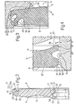
- reference numeral 1 indicates a rolling bearing with a single circle of balls, comprising an outer race 2, an inner race 3, a circle of balls 4 and a spacing cage 5.
- Member 6 (Figs. 2, and 4) is substantially ring-shaped and is made of a soft and resilient material, such as an elastomeric material, rubber or plastic resin.
- Member 6 is substantially flat and has a first face 8 perpendicular to the axis of the said race and a second face 9 which is substantially parallel to the said face 8 and has a first inclined annular surface 10 extending away from the face 8 and a second annular concave surface 11.
- the said member has an outer edge 12, configured in such a way as to mate with a seating 14 formed on an inner surface 7 of the outer race 2 and provided with an annular projection 17 and an annular groove 21, and an inner edge 13 configured in such a way as to create a seal on the surface 15 of the inner race 3 of the bearing 1.
- the outer edge 12 originates from the side surface 16 of the member 6, which surface is inclined in such a manner as to extend away from the axis of the said member as it approaches the face 9, and comprises a root section 18 from which a first annular lip 19 and a second annular lip 20 originate.
- the annular lip 19 extends in a substantially radial direction, is delimited towards the other lip 20 by a substantially conical surface 19a and is truncated by an annular surface 22 perpendicular to the face 8 and which is jointed without solution of continuity, by means of a fillet 23, to the inclined surface 10 of the face 9.
- the second annular lip 20 Originating from the base of the lip 19 and from the base of the root section 18 is the second annular lip 20 of substantially rectangular cross-section, which extends in a substantially radial direction following a pre-established inclination so as to result in being parallel to the surface 19a of the first lip 19. Lip 20 extends to such a length that its radial dimension is equal to that of the lip 19.
- the inner edge 13 comprises a third annular lip 24, a fourth annular lip 25 and an annular cavity 26 formed between the said lips.
- the annular lip 25 originates directly from an inner end 27 of the ring 7 and extends towards the axis of the said ring 7 in a substantially radial direction and is delimited by a surface 28 which is configured like the surface 11.
- Annular lip 24 also originates from the end 27, is perpendicular to the axis of the ring 7 and extends towards it, is delimited externally by the face 8 and has a bevel 31. Both lips 24, 25 are delimited by a surface 32 parallel to the axis of the member 6.
- the length of the lips 24 and 25 in radial direction is such that when the member 6 is mounted in the bearing 1, between the end surface 32 of the said lips, and the outer surface 15 of the inner race 3 a clearance is created which has a pre-established dimension indicated by a in Fig. 4.
- Figure 5 shows a member 6 according to another embodiment almost completely similar to that of Fig. 2.
- the member 6 of this second embodiment is shaped substantially in the same manner as the member described hereinabove, except the edge 13; equal parts are indicated by the same reference numerals.
- the inner edge 13 (Fig. 6) has an annular lip 24 perpendicular to the axis of the member 6 which projects in a radial direction and which is truncated by a surface 32 parallel to the said axis so as to leave between the said surface 32 and the surface 15 of the inner race 3, after the assembly has been accomplished, a pre-established clearance a; it has an annular lip 25 and a cavity 25 between the said lips 24 and 25.
- Lip 25 is configured in a different way relative to the corresponding lip of the ring of Fig. 2. It extends, beginning from the end 27, in a direction substantially parallel to the lip 24 and has a first section 33 which is delimited by the surface 28 and a second section 34 perpendicular to the axis of the member 6 and terminating with an end 35 apt to slide on the surface 15 of the inner race 3.
- the length of the lip 25 is such that when the member 6 is being mounted in the bearing 1, an interference between the said lip 25 and the inner race 3 is created.
- lip 19 is intended to withstand an expulsion force slightly higher than the force exerted onto the member during the service. After having overcome this force, lip 19 deforms resiliently in the direction opposed to the direction of introduction and allows the extraction of the member 6, reassu.ming then its original configuration. In this way it is possible to disassemble the said member without breaking it.
- the inner edge 13 of the member 6, as described hereinabove, is almost in contact with the surface 15 of the inner race 3, which usually is movable relative to the outer race 2.
- the limited clearance a provides a first labyrinth seal between the annular lip 24 and the surface 15 and a second labyrinth seal between the annular lip 25 and the same surface 15.
- the annular space 26 between the lips 24 and 25 further improves the overall seal of the edge 13 in respect of both the external contamination agents and the lubricant within the bearing 1, behaving like a collection chamber in which the eventual infiltrations stop and accumulate. By filling the space 26 with grease when carrying out the assembly, the seal is further improved.
- the edge 13 behaves in a slightly different manner.
- the limited clearance a formed between the lip 24 and the race 3 provides a labyrinth seal improved by the presence of the collection chamber formed by the space 26, but because of the interference between the inner race 3 and the lip 25, this latter is resiliently deformed and exerts with the end 35 and onto the surface 15 a radial pressure proportional to its own deformation, thus providing a sliding seal between the races 2 and 3 of the bearing 1, which move relative to one another.
- the bevel 31 and the concave surface 11 of the face 9 foster centrifugal action exerted in respect of the contamination agents and in respect of the lubricant contained within the bearing. Moreover, the concave shape of the said surface reduces the overall dimensions of the member 6 in respect of the balls 4.
- the particular shape of the outer edge 12 allows an easy assembly and disassembly of the protection and seal member and thus allows carrying out periodical inspections and substitutions of the lubricant contained in the bearing. Furthermore, the edge 12 is arranged to couple with seatings 14 of already known and standardized type, so that it is not necessary to change the working operations carried out on the races of the bearings which are being produced at present time.
- protection and seal members as that shown in Figures 2 and 4 may be produced, in which the dimensions of the lips 24 and 25 are such as to deliberately create an interference with the surface 15 of the race 3. In this way, after an initial period of time corresponding to the period of running-in of the bearing and in which the friction is rather high, the conditions of zero clearance are achieved, which are ideal for obtaining the maximum sealing efficiency and cannot be achieved during manufacture, not even with the most restrictive tolerances.
Landscapes
- Engineering & Computer Science (AREA)
- General Engineering & Computer Science (AREA)
- Mechanical Engineering (AREA)
- Sealing Of Bearings (AREA)
- Rolling Contact Bearings (AREA)
Claims (6)
Applications Claiming Priority (2)
| Application Number | Priority Date | Filing Date | Title |
|---|---|---|---|
| IT6883780 | 1980-12-02 | ||
| IT6883780A IT1129925B (it) | 1980-12-02 | 1980-12-02 | Organo di protezione e di tenuta per cuscinetti volventi |
Publications (2)
| Publication Number | Publication Date |
|---|---|
| EP0053334A1 EP0053334A1 (de) | 1982-06-09 |
| EP0053334B1 true EP0053334B1 (de) | 1985-03-06 |
Family
ID=11310697
Family Applications (1)
| Application Number | Title | Priority Date | Filing Date |
|---|---|---|---|
| EP19810109806 Expired EP0053334B1 (de) | 1980-12-02 | 1981-11-20 | Schutz- und Dichtelement für Wälzlager |
Country Status (5)
| Country | Link |
|---|---|
| US (1) | US4428629A (de) |
| EP (1) | EP0053334B1 (de) |
| JP (1) | JPS57146915A (de) |
| DE (1) | DE3169204D1 (de) |
| IT (1) | IT1129925B (de) |
Families Citing this family (22)
| Publication number | Priority date | Publication date | Assignee | Title |
|---|---|---|---|---|
| DE3443750A1 (de) * | 1984-11-30 | 1986-06-05 | SWF Auto-Electric GmbH, 7120 Bietigheim-Bissingen | Vorrichtung, insbesondere hubwischeranlage fuer kraftfahrzeuge |
| JPS6218443U (de) * | 1985-07-18 | 1987-02-03 | ||
| US4805919A (en) * | 1987-07-14 | 1989-02-21 | Wasley Products, Inc. | Bearing seal |
| JPH03127821U (de) * | 1990-04-06 | 1991-12-24 | ||
| JP3753256B2 (ja) * | 1994-08-09 | 2006-03-08 | 日本トムソン株式会社 | 直動転がり案内ユニット |
| NL9401721A (nl) * | 1994-10-18 | 1996-06-03 | Skf Ind Trading & Dev | Wentellager met olie-afdichting. |
| JPH08135668A (ja) * | 1994-11-14 | 1996-05-31 | Nippon Seiko Kk | 密封板付転がり軸受 |
| US5909880A (en) * | 1997-02-21 | 1999-06-08 | The Torrington Company | Polymer bearing seal and sealed bearing |
| DE19709056B4 (de) * | 1997-03-06 | 2006-01-26 | Ina-Schaeffler Kg | Abdichtung für ein Kupplungsausrücklager |
| SE9801039L (sv) * | 1998-03-27 | 1999-06-21 | Itt Mfg Enterprises Inc | Tätningsbricka för avtätning av ett rullningslager |
| US6179472B1 (en) * | 1998-10-13 | 2001-01-30 | International Business Machines Corporation | Ball bearing oil/grease loss containment method |
| DE60010767T3 (de) * | 1999-03-09 | 2012-01-19 | Nsk Ltd. | Kupplungsausrücklager |
| FR2790802B1 (fr) | 1999-03-10 | 2001-04-20 | Roulements Soc Nouvelle | Ensemble preassemble formant joint a etancheite magnetique et roulement ou palier incorporant un tel ensemble |
| JP2002286044A (ja) * | 2000-04-27 | 2002-10-03 | Nsk Ltd | トランスミッション用密封板付転がり軸受及びトランスミッション |
| EP2287481B1 (de) * | 2008-06-13 | 2017-02-08 | NTN Corporation | Halter, rillenkugellager und lager mit abdichtung |
| US9217472B2 (en) | 2008-11-06 | 2015-12-22 | Ntn Corporation | Seal equipped bearing assembly |
| JP5300420B2 (ja) * | 2008-11-06 | 2013-09-25 | Ntn株式会社 | シール付き軸受 |
| DE102009015066A1 (de) * | 2009-03-26 | 2010-09-30 | Schaeffler Technologies Gmbh & Co. Kg | Ausrücklager |
| DE102009050215A1 (de) * | 2009-10-22 | 2011-05-12 | Schaeffler Technologies Gmbh & Co. Kg | Nichtschleifender Dichtungsring und Dichtungsanordnung |
| US10508701B2 (en) * | 2017-04-06 | 2019-12-17 | The Pullman Company | Vehicle suspension bushing assembly and method of assembling the same |
| IT202100021353A1 (it) | 2021-08-06 | 2023-02-06 | Skf Ab | Unita’ cuscinetto |
| IT202200014854A1 (it) * | 2022-07-15 | 2024-01-15 | Skf Ab | Unita’ cuscinetto a corpi volventi |
Family Cites Families (9)
| Publication number | Priority date | Publication date | Assignee | Title |
|---|---|---|---|---|
| CH416242A (it) * | 1964-06-16 | 1966-06-30 | Riv Officine Di Villar Perosa | Elemento di tenuta stagna per cuscinetti a rotolamento |
| US3366428A (en) | 1965-09-17 | 1968-01-30 | Mcgill Mfg Company Inc | Bearing assembly and seal |
| US3350148A (en) | 1966-02-11 | 1967-10-31 | Gen Bearing Co | Ball bearing seal assembly |
| DE1983845U (de) * | 1966-06-17 | 1968-04-18 | Riv Officine Di Villar Perosa | Schutzscheibe fuer lager. |
| US3572857A (en) * | 1967-10-14 | 1971-03-30 | Toyo Bearing Mfg Co | Antifriction bearing seal |
| US3642335A (en) * | 1969-09-12 | 1972-02-15 | Nippon Seiko Kk | Sealed bearing |
| US3709572A (en) * | 1970-12-16 | 1973-01-09 | Textron Inc | Reversible shield-seal for a bearing |
| US3700296A (en) * | 1971-01-15 | 1972-10-24 | Ernst Bugmann | Antifriction bearing |
| US3797899A (en) | 1971-09-27 | 1974-03-19 | Trw Inc | Multiple lip outer land riding seal |
-
1980
- 1980-12-02 IT IT6883780A patent/IT1129925B/it active
-
1981
- 1981-11-20 EP EP19810109806 patent/EP0053334B1/de not_active Expired
- 1981-11-20 DE DE8181109806T patent/DE3169204D1/de not_active Expired
- 1981-11-27 US US06/325,193 patent/US4428629A/en not_active Expired - Fee Related
- 1981-12-02 JP JP19302281A patent/JPS57146915A/ja active Pending
Also Published As
| Publication number | Publication date |
|---|---|
| EP0053334A1 (de) | 1982-06-09 |
| IT1129925B (it) | 1986-06-11 |
| IT8068837A0 (it) | 1980-12-02 |
| DE3169204D1 (en) | 1985-04-11 |
| JPS57146915A (en) | 1982-09-10 |
| US4428629A (en) | 1984-01-31 |
Similar Documents
| Publication | Publication Date | Title |
|---|---|---|
| EP0053334B1 (de) | Schutz- und Dichtelement für Wälzlager | |
| US4525082A (en) | Sealing ring assembly for rolling bearings | |
| CA1261894A (en) | Unitized seal | |
| US5378000A (en) | Shaft seal assembly | |
| US4512672A (en) | Front seal for bearing cups | |
| US4339158A (en) | End cap assemblies for conveyor rollers | |
| EP1546586B1 (de) | Verbindundselement und montageverfahren für eine dichtung | |
| EP0303359B1 (de) | Dichtung | |
| US20080001362A1 (en) | Split bearing isolator and a method for assembling seal | |
| CA2035013A1 (en) | Static and dynamic shaft seal assembly | |
| EP1058792A1 (de) | Lagerabdichtungen | |
| EP0265113B1 (de) | Geformte Gummidichtung für eine aus einem Lager und einem gepressten Gehäuse bestehende Einheit | |
| US4655618A (en) | Needle bearing and in particular a needle sleeve having a reinforced seal | |
| US2915345A (en) | Fluid seal | |
| EP1070211B1 (de) | Einrastbarer lagerisolator | |
| US4478463A (en) | Conical roller bearing | |
| ES8401577A1 (es) | Un dispositivo de cojinete de empuje estanqueizado. | |
| CA2176751C (en) | Machined shaft seal encased in an elastomeric sleeve | |
| GB2066378A (en) | Linear recirculating rolling bearing | |
| US4555188A (en) | Bearing and seal assembly | |
| US6834859B2 (en) | Labyrinth grease hub seal | |
| CN108105265A (zh) | 密封装置,特别适用于滚动轴承 | |
| EP0046321A1 (de) | Einbau eines Dichtungsringes in ein Wälzlager und zu diesem Einbau bestimmter Dichtungsring | |
| CN215567275U (zh) | 一种轧机用轴承组件 | |
| GB2046876A (en) | Conveyor rollers |
Legal Events
| Date | Code | Title | Description |
|---|---|---|---|
| PUAI | Public reference made under article 153(3) epc to a published international application that has entered the european phase |
Free format text: ORIGINAL CODE: 0009012 |
|
| AK | Designated contracting states |
Designated state(s): DE FR GB SE |
|
| 17P | Request for examination filed |
Effective date: 19820927 |
|
| GRAA | (expected) grant |
Free format text: ORIGINAL CODE: 0009210 |
|
| AK | Designated contracting states |
Designated state(s): DE FR GB SE |
|
| REF | Corresponds to: |
Ref document number: 3169204 Country of ref document: DE Date of ref document: 19850411 |
|
| ET | Fr: translation filed | ||
| PLBE | No opposition filed within time limit |
Free format text: ORIGINAL CODE: 0009261 |
|
| STAA | Information on the status of an ep patent application or granted ep patent |
Free format text: STATUS: NO OPPOSITION FILED WITHIN TIME LIMIT |
|
| 26N | No opposition filed | ||
| REG | Reference to a national code |
Ref country code: FR Ref legal event code: TP |
|
| REG | Reference to a national code |
Ref country code: GB Ref legal event code: 732E |
|
| EAL | Se: european patent in force in sweden |
Ref document number: 81109806.0 |
|
| PGFP | Annual fee paid to national office [announced via postgrant information from national office to epo] |
Ref country code: FR Payment date: 20001101 Year of fee payment: 20 |
|
| PGFP | Annual fee paid to national office [announced via postgrant information from national office to epo] |
Ref country code: DE Payment date: 20001102 Year of fee payment: 20 |
|
| PGFP | Annual fee paid to national office [announced via postgrant information from national office to epo] |
Ref country code: GB Payment date: 20001103 Year of fee payment: 20 |
|
| PGFP | Annual fee paid to national office [announced via postgrant information from national office to epo] |
Ref country code: SE Payment date: 20001106 Year of fee payment: 20 |
|
| PG25 | Lapsed in a contracting state [announced via postgrant information from national office to epo] |
Ref country code: GB Free format text: LAPSE BECAUSE OF EXPIRATION OF PROTECTION Effective date: 20011119 |
|
| PG25 | Lapsed in a contracting state [announced via postgrant information from national office to epo] |
Ref country code: SE Free format text: THE PATENT HAS BEEN ANNULLED BY A DECISION OF A NATIONAL AUTHORITY Effective date: 20011129 |
|
| REG | Reference to a national code |
Ref country code: GB Ref legal event code: PE20 Effective date: 20011119 |