EP0052702A2 - Dispositif de sécurité pour machines de construction - Google Patents
Dispositif de sécurité pour machines de construction Download PDFInfo
- Publication number
- EP0052702A2 EP0052702A2 EP81106857A EP81106857A EP0052702A2 EP 0052702 A2 EP0052702 A2 EP 0052702A2 EP 81106857 A EP81106857 A EP 81106857A EP 81106857 A EP81106857 A EP 81106857A EP 0052702 A2 EP0052702 A2 EP 0052702A2
- Authority
- EP
- European Patent Office
- Prior art keywords
- construction machine
- sensor
- gate
- output
- signal
- Prior art date
- Legal status (The legal status is an assumption and is not a legal conclusion. Google has not performed a legal analysis and makes no representation as to the accuracy of the status listed.)
- Granted
Links
- 238000010276 construction Methods 0.000 title claims abstract description 63
- 230000003287 optical effect Effects 0.000 claims abstract description 13
- 230000001960 triggered effect Effects 0.000 claims description 8
- 238000013459 approach Methods 0.000 claims description 3
- 239000003990 capacitor Substances 0.000 claims description 3
- 230000006835 compression Effects 0.000 claims description 2
- 238000007906 compression Methods 0.000 claims description 2
- 238000009499 grossing Methods 0.000 claims description 2
- 230000001629 suppression Effects 0.000 claims description 2
- 239000002689 soil Substances 0.000 description 3
- 230000006378 damage Effects 0.000 description 2
- 238000010586 diagram Methods 0.000 description 2
- 238000003384 imaging method Methods 0.000 description 2
- 238000012634 optical imaging Methods 0.000 description 2
- 230000000717 retained effect Effects 0.000 description 2
- BUGBHKTXTAQXES-UHFFFAOYSA-N Selenium Chemical compound [Se] BUGBHKTXTAQXES-UHFFFAOYSA-N 0.000 description 1
- 208000027418 Wounds and injury Diseases 0.000 description 1
- 230000004888 barrier function Effects 0.000 description 1
- 230000007423 decrease Effects 0.000 description 1
- 230000001419 dependent effect Effects 0.000 description 1
- 208000014674 injury Diseases 0.000 description 1
- 238000000034 method Methods 0.000 description 1
- 229910052711 selenium Inorganic materials 0.000 description 1
- 239000011669 selenium Substances 0.000 description 1
Images


Classifications
-
- E—FIXED CONSTRUCTIONS
- E01—CONSTRUCTION OF ROADS, RAILWAYS, OR BRIDGES
- E01C—CONSTRUCTION OF, OR SURFACES FOR, ROADS, SPORTS GROUNDS, OR THE LIKE; MACHINES OR AUXILIARY TOOLS FOR CONSTRUCTION OR REPAIR
- E01C19/00—Machines, tools or auxiliary devices for preparing or distributing paving materials, for working the placed materials, or for forming, consolidating, or finishing the paving
- E01C19/22—Machines, tools or auxiliary devices for preparing or distributing paving materials, for working the placed materials, or for forming, consolidating, or finishing the paving for consolidating or finishing laid-down unset materials
- E01C19/23—Rollers therefor; Such rollers usable also for compacting soil
- E01C19/28—Vibrated rollers or rollers subjected to impacts, e.g. hammering blows
-
- B—PERFORMING OPERATIONS; TRANSPORTING
- B60—VEHICLES IN GENERAL
- B60K—ARRANGEMENT OR MOUNTING OF PROPULSION UNITS OR OF TRANSMISSIONS IN VEHICLES; ARRANGEMENT OR MOUNTING OF PLURAL DIVERSE PRIME-MOVERS IN VEHICLES; AUXILIARY DRIVES FOR VEHICLES; INSTRUMENTATION OR DASHBOARDS FOR VEHICLES; ARRANGEMENTS IN CONNECTION WITH COOLING, AIR INTAKE, GAS EXHAUST OR FUEL SUPPLY OF PROPULSION UNITS IN VEHICLES
- B60K28/00—Safety devices for propulsion-unit control, specially adapted for, or arranged in, vehicles, e.g. preventing fuel supply or ignition in the event of potentially dangerous conditions
-
- B—PERFORMING OPERATIONS; TRANSPORTING
- B60—VEHICLES IN GENERAL
- B60Q—ARRANGEMENT OF SIGNALLING OR LIGHTING DEVICES, THE MOUNTING OR SUPPORTING THEREOF OR CIRCUITS THEREFOR, FOR VEHICLES IN GENERAL
- B60Q9/00—Arrangement or adaptation of signal devices not provided for in one of main groups B60Q1/00 - B60Q7/00, e.g. haptic signalling
Definitions
- the invention relates to a safety device on construction machines.
- the invention is based on the object of avoiding dangerous situations which can arise as the construction machine approaches an edge.
- An optical or acoustic warning signal can be triggered by the error signal.
- the construction machine can also be stopped by the error signal. This warns the machine operator of a dangerous situation or prevents the construction machine from approaching an edge at all.
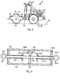
- FIG. 5 shows a construction machine 10 in the form of a vibration roller with driver's cab-12. At least one sensor is provided on each side of the construction machine 10 and responds to the floor surface approximately in the contact plane 14 of the construction machine 10.
- a sensor 16 contains an optical transmitter part 18 and a photoelectric receiver part 20, which are arranged on both sides of a roller body 22 on a roller frame 24, so that the sensor 16 responds to the floor surface in a region 26 at the level of the roller body contact line.
- a corresponding receiver part 20A can cooperate with the transmitter part 18 on the upper longitudinal beam 28.
- a transmitter part 30 and a receiver part 32 can form a sensor 34 which responds to the ground surface in an area 36 in the extension of the wheel contact lines.
- Such a sensor e.g. the sensor 16 is shown in Fig. 3.
- the transmitter part 18 has a cylindrical housing 38.
- a light bulb 42 with a straight filament 44 is seated in one end wall 40 of the housing 38.
- the filament 44 is imaged in a plane 50 as a filament image 52 by a first optical imaging system in the form of a lens 46 with the optical axis 48.
- a transparent cover 56 is arranged in front of the slit diaphragm 54.
- the receiver part 20 also has a cylindrical housing 58.
- a selenium barrier photo element 60 or another active photoelectric component with a receiver surface is provided which corresponds in size and position to the position of the helix 44 in the housing 38.
- a region 66 in the plane 50 is imaged on the photoelectric receiver 60 by a second optical imaging system in the form of a lens 62 with an optical axis 64.
- the spiral image 52 and the region 66 are shown rotated by 90 ° in the paper plane in FIG. 3. In fact, both lie in the plane 50.
- a slot diaphragm 68 is likewise arranged in the housing 58.
- the housing 58 is closed off by a transparent housing cover 70.
- transmitter part 18 and receiver part 20 form a V-shaped beam path. If a remitting surface, that is to say the floor surface, is located in plane 50, then a real image of the helical image generated by first imaging system 46 is generated by second imaging system 62 in plane of photoelectric receiver 60.
- the spiral image 52 and the area 66 detected by the photoelectric receiver 60 overlap only partially in the plane 50. If the remitting floor surface lies below the plane 50, the overlap rapidly decreases, so that the photoelectric Receiver then no longer delivers a signal. On the other hand, if the floor surface is above level 50, the overlap increases. The signal at the photoelectric receiver 60 is therefore retained. The sensor 16 thus responds to a falling surface by the absence of the receiver signal. However, it does not yet provide an error signal if the floor surface rises slightly above level 50. The sensor 16 with the transmitter part 18 and the receiver part 20 is arranged so that the plane 50 corresponds approximately to the contact plane 14.
- the light source ie the incandescent lamp 42
- the light source is modulated with an alternating frequency. This can be done in such a way that a square wave voltage of five to ten Hertz is applied to the connection terminals 72 of the incandescent lamp 42.
- the photoelectric receiver 60 then receives, in addition to a constant light component and a light intensity modulated by the movement of the construction machine 10 and the non-uniform remission of the floor surface, a component that corresponds to the alternating frequency of the light source is modulated.
- the output signal of the photoelectric receiver 60 appears at output terminals 74. In order to separate this alternating light component of the receiver signal from the constant light component and the other interference components, as shown in FIG.
- the receiver signal is connected to a ring modulator 76 which is controlled with the alternating frequency , with which the light source is modulated, that is to say with the square-wave voltage which is present at the terminals 72 of the incandescent lamp 42.
- the ring modulator 76 contains four diodes 78, 80, 82 and 84, which are arranged in the same direction in a bridge.
- the receiver signal lies over an input transformer 86 - at two diametrically opposite points of the bridge, while the control signal, that is, the square wave voltage, is present between the two other corner points of the bridge via an input transformer 88.
- An output voltage becomes between the center taps 90, 92 of the input transformer 86 and 88 tapped.
- RC element consisting of a resistor 94 and a capacitor 96 for smoothing the ring modulator output signal.
- the DC voltage at the capacitor 96 of the RC element is for
- Noise suppression connected via a diode 98 to an output 100 to which a resistor 102 is connected in parallel.
- the circuit described represents a correlation circuit that delivers an output signal when the photoelectric receiver 60. Via the helical pattern 52 delivers an alternating signal with the alternating frequency of the incandescent lamp 42., I.e. if the sensor 16 or 34 in the contact plane 14 of the construction machine 10 or recorded above this level of the surface of the soil. The signal from the sensor 16 or 34 disappears when the ground surface touches the Areas 26 or 36 drop noticeably below the contact plane 14 of the construction machine.
- the output signals of the various sensors 16, 34 ... are at inputs 104 of an AND gate 106. If one of these output signals is omitted, the output signal at the output 108 of the AND gate 106 goes into the logic state "0". This state at output 108 represents the "error signal".
- an optical or acoustic warning signal can be triggered by the error signal.
- the construction machine can be stopped by the error signal.
- a restart device which can be actuated by a separate key is provided, by means of which at least the travel drive of the construction machine 10 which has been shut down by the error signal can be switched on again.
- the output signal of the AND gate 106 negated by an inverter 110 switches on an optical or acoustic warning device via a relay 112.
- the negated output signal of the AND gate 106 also switches off the vibrating device via a switching element 114.
- the error signal from output 108 is present at an input of an EXCLUSIVE OR gate 116.
- a voltage is present at the other input of the EXCLUSIVE-OR gate 116 via a contact 118, which can be actuated in the closing sense by the key of the restart device.
- the output signal of the EXCLUSIVE-OR gate 116 controls a relay 122 via an inverter 120, by means of which the construction machine can be switched off.
- the EXCLUSIVE-OR gate 116 supplies a signal at its output if and only if a signal appears at the output of the AND gate 1 06 and the contact 118 of the restart device is open or the output signal at the output 108 of the AND gate 106 "0 "and contact 118 is closed.
- the normal case is that the contact 118 is open and at all.
- Inputs 104 of the AND gate 106 have sensor signals so that the output 108 of the AND gate 106 is in the "L" state.
- the EXCLUSIVE-OR gate 116 supplies the signal "L” at its output, which is negated by the inverter 120 to "0". Relay 122 has dropped out and the construction machine is operating.
- the contact 118 can be closed by the restart device. As a result, the output of the EXCLUSIVE-OR gate 116 becomes "L" again. Relay 122 drops out and puts the construction machine back into operation.
- a separate key can be provided, which is expediently provided by a supervisor. Person or the operator's safety officer should be kept in custody.
- the EXCLUSIVE-OR gate 116 also ensures that the construction machine cannot be operated with the contact 118 permanently closed. In this case, the signal "L" would normally be present at both inputs of the EXCLUSIVE-OR gate 116, so that the construction machine would be stopped.
- the vibration device is in any case stopped when an error signal occurs at the output 108, even if the drive of the construction machine is switched on again via the contact 118.
- the restart device allows the construction machine to be started up again and brought out of the danger zone.
- a device 124 can be provided at at least one location on the construction machine 10, which device allows a tensile force to be applied to the construction machine 10.
- the construction machine can then be connected to a second, parallel running construction machine by means of a rope, and this rope, e.g. by a suspended weight, a tensile force directed away from the slope edge is exerted on the tensile force sensor 146 or 146A of the device 124 or 124A. This responds when a predetermined minimum tractive force is reached.
- the traction force sensor can then be switched so that the error signal cannot be triggered by the sensors 16, 34 on the side of the construction machine 10 facing the slope when it has responded.
- This can be achieved by the circuit shown in FIG. 2.
- the output signals of the sensors 16, 34 on one side are applied to the inputs 126 of an AND gate 128.
- the output of the AND gate 128 and the output signal of the traction force sensor, which is symbolized here by a contact 130, are connected together. If the traction force sensor has responded, that is to say the contact 130 is closed, then no error signal occurs, even if a sensor signal on the AND gate 128 is omitted.
- a device 124 for attacking a tensile force with an associated sensor is preferably arranged for each side of the construction machine 10. It is particularly advantageous to combine two devices 124 and 124A for both machine sides in one construction, as shown in FIG. 6.
- the devices 124, 124A for attacking a tensile force each have an eye or a hook 132, 132A, which are connected to one another by a rod 134 extending transversely to the construction machine 10.
- the rod 134 is guided in a housing 136 fastened to the construction machine 10 in two end walls 138 and 138A and an intermediate wall 140.
- Disks 142, 142A are fastened on the rod 134 on both sides of the intermediate wall 140 at a distance from one another.
- a prestressed compression spring 144, 144A is arranged between each end wall 138, 138A and the adjacent disk 142, 142A.
- the tensile force sensors are formed by switches 146, 146A, which can be actuated by the disks 142A and 142 when they approach the intermediate wall 140.
- the tensile force sensors are represented by the contact 130 and a contact 130A.
- the sensor signals from the sensors on the side facing away from the device 132A are present at inputs 126A of an AND gate 128A.
- the sensor signal via the switch 130A and the output of the AND gate 128A are also connected together.
- the interconnected signals are present at the two inputs of an AND gate 148, the output 108 'of which corresponds to the output 108 of FIG. 1.
- the rest of the circuit is the same as in FIG. 1
- the individual parts of the device 124, 124A, their attachment to the construction machine 10 and the traction rope leading to the second construction machine are designed in such a strength that the required holding forces are transmitted with sufficient security when the construction machine 10 slips over the edge of the slope.
Landscapes
- Engineering & Computer Science (AREA)
- Mechanical Engineering (AREA)
- Human Computer Interaction (AREA)
- Chemical & Material Sciences (AREA)
- Combustion & Propulsion (AREA)
- Transportation (AREA)
- Architecture (AREA)
- Civil Engineering (AREA)
- Structural Engineering (AREA)
- Component Parts Of Construction Machinery (AREA)
- Jib Cranes (AREA)
Priority Applications (1)
| Application Number | Priority Date | Filing Date | Title |
|---|---|---|---|
| AT81106857T ATE18027T1 (de) | 1980-11-26 | 1981-09-02 | Sicherheitsvorrichtung an baumaschinen. |
Applications Claiming Priority (2)
| Application Number | Priority Date | Filing Date | Title |
|---|---|---|---|
| DE19803044485 DE3044485A1 (de) | 1980-11-26 | 1980-11-26 | Sicherheitsvorrichtung an baumaschinen |
| DE3044485 | 1980-11-26 |
Publications (3)
| Publication Number | Publication Date |
|---|---|
| EP0052702A2 true EP0052702A2 (fr) | 1982-06-02 |
| EP0052702A3 EP0052702A3 (en) | 1984-02-29 |
| EP0052702B1 EP0052702B1 (fr) | 1986-02-19 |
Family
ID=6117603
Family Applications (1)
| Application Number | Title | Priority Date | Filing Date |
|---|---|---|---|
| EP81106857A Expired EP0052702B1 (fr) | 1980-11-26 | 1981-09-02 | Dispositif de sécurité pour machines de construction |
Country Status (3)
| Country | Link |
|---|---|
| EP (1) | EP0052702B1 (fr) |
| AT (1) | ATE18027T1 (fr) |
| DE (2) | DE3044485A1 (fr) |
Cited By (3)
| Publication number | Priority date | Publication date | Assignee | Title |
|---|---|---|---|---|
| EP0195463A3 (fr) * | 1985-03-11 | 1988-03-16 | Applied Power Inc. | Embrayage hydraulique à cylindre principal et auxiliaire et à système de sécurité pour assurer l'actuation positive de l'embrayage |
| EP2021730A4 (fr) * | 2006-05-12 | 2009-06-17 | Conplant Pty Ltd | Alarme d'inclinaison pour une machine mobile |
| US20230287635A1 (en) * | 2022-03-11 | 2023-09-14 | Caterpillar Paving Products Inc. | Method and system for operating compaction machines |
Citations (3)
| Publication number | Priority date | Publication date | Assignee | Title |
|---|---|---|---|---|
| DE579545C (de) | 1933-06-28 | Buckau R Wolf Akt Ges Maschf | Selbsttaetige Absturzsicherung fuer schwere Gleiskettenfahrzeuge, wi?er, Absetzer und aehnliche Geraete, die am Rand von Boeschungen entla?ren | |
| FR2289954A1 (fr) | 1974-10-24 | 1976-05-28 | Inst Mek Mashin Akadem | Dispositif optique pour systeme de commande automatique d'engins a l'aide d'un programme a contraste lumineux |
| FR2352692A1 (fr) | 1976-05-25 | 1977-12-23 | Morin Roy Georges | Dispositif de securite contre les risques de renversement des engins mobiles |
-
1980
- 1980-11-26 DE DE19803044485 patent/DE3044485A1/de not_active Ceased
-
1981
- 1981-09-02 AT AT81106857T patent/ATE18027T1/de not_active IP Right Cessation
- 1981-09-02 DE DE8181106857T patent/DE3173809D1/de not_active Expired
- 1981-09-02 EP EP81106857A patent/EP0052702B1/fr not_active Expired
Patent Citations (3)
| Publication number | Priority date | Publication date | Assignee | Title |
|---|---|---|---|---|
| DE579545C (de) | 1933-06-28 | Buckau R Wolf Akt Ges Maschf | Selbsttaetige Absturzsicherung fuer schwere Gleiskettenfahrzeuge, wi?er, Absetzer und aehnliche Geraete, die am Rand von Boeschungen entla?ren | |
| FR2289954A1 (fr) | 1974-10-24 | 1976-05-28 | Inst Mek Mashin Akadem | Dispositif optique pour systeme de commande automatique d'engins a l'aide d'un programme a contraste lumineux |
| FR2352692A1 (fr) | 1976-05-25 | 1977-12-23 | Morin Roy Georges | Dispositif de securite contre les risques de renversement des engins mobiles |
Cited By (3)
| Publication number | Priority date | Publication date | Assignee | Title |
|---|---|---|---|---|
| EP0195463A3 (fr) * | 1985-03-11 | 1988-03-16 | Applied Power Inc. | Embrayage hydraulique à cylindre principal et auxiliaire et à système de sécurité pour assurer l'actuation positive de l'embrayage |
| EP2021730A4 (fr) * | 2006-05-12 | 2009-06-17 | Conplant Pty Ltd | Alarme d'inclinaison pour une machine mobile |
| US20230287635A1 (en) * | 2022-03-11 | 2023-09-14 | Caterpillar Paving Products Inc. | Method and system for operating compaction machines |
Also Published As
| Publication number | Publication date |
|---|---|
| ATE18027T1 (de) | 1986-03-15 |
| DE3044485A1 (de) | 1982-06-03 |
| EP0052702A3 (en) | 1984-02-29 |
| DE3173809D1 (en) | 1986-03-27 |
| EP0052702B1 (fr) | 1986-02-19 |
Similar Documents
| Publication | Publication Date | Title |
|---|---|---|
| DE69023492T2 (de) | Maschinennäherungssensor. | |
| DE3717771C2 (fr) | ||
| DE10026305A1 (de) | Optoelektronische Vorrichtung | |
| DE2406369C2 (de) | Tankfüllstand-Kontrollvorrichtung | |
| EP3339715A1 (fr) | Système de protection d'accès | |
| DE3908273C1 (en) | Self-test device for a scanning light probe | |
| DE3837054C2 (de) | Gefahrenmeldeanlage für ein Fahrzeug insbesondere ein Flurförderzeug | |
| DE102019131774A1 (de) | Überwachungssystem für Roboter und Robotersystem | |
| DE10055689B4 (de) | Verfahren zum Betrieb eines optischen Triangulationslichtgitters | |
| DE20103828U1 (de) | Sicherheitseinrichtung zur Überwachung eines Durchgangs | |
| EP3415804B1 (fr) | Dispositif de sécurité | |
| EP1408273A2 (fr) | Dispositif de protection pour contrôler une zone de protection liée à un élémemt mobile | |
| EP0418989A2 (fr) | Barrière de lumière | |
| DE3536472A1 (de) | Tiefenmesseinrichtung fuer krananlagen | |
| DE1905016C3 (de) | SichtweitenmeBeinrichtung | |
| EP0052702A2 (fr) | Dispositif de sécurité pour machines de construction | |
| DE3509228A1 (de) | System zur verhinderung eines kontaktes zwischen einem analysekopf und einer transparenten trommel in einem farbabtaster | |
| EP0909959A2 (fr) | Dispositif de protection de la zone posterieure ou laterale d'un vehicule | |
| EP1826589A1 (fr) | Capteur optique destiné à la surveillance d'une zone de sécurité | |
| EP1110901B1 (fr) | Appareil de surveillance de l'usure des galets pour escalier roulant | |
| DE202021104977U1 (de) | Überwachungseinrichtung | |
| DE3131490C2 (fr) | ||
| EP0049794A2 (fr) | Appareil de commutation électronique fonctionnant sans contact | |
| EP3862617B1 (fr) | Dispositif de sécurisation d'une zone dangereuse | |
| DE9416314U1 (de) | Rauchmelder |
Legal Events
| Date | Code | Title | Description |
|---|---|---|---|
| PUAI | Public reference made under article 153(3) epc to a published international application that has entered the european phase |
Free format text: ORIGINAL CODE: 0009012 |
|
| AK | Designated contracting states |
Designated state(s): AT DE FR GB IT SE |
|
| PUAL | Search report despatched |
Free format text: ORIGINAL CODE: 0009013 |
|
| AK | Designated contracting states |
Designated state(s): AT DE FR GB IT SE |
|
| 17P | Request for examination filed |
Effective date: 19840210 |
|
| GRAA | (expected) grant |
Free format text: ORIGINAL CODE: 0009210 |
|
| RAP1 | Party data changed (applicant data changed or rights of an application transferred) |
Owner name: CASE VIBROMAX GMBH & CO. KG |
|
| AK | Designated contracting states |
Designated state(s): AT DE FR GB IT SE |
|
| REF | Corresponds to: |
Ref document number: 18027 Country of ref document: AT Date of ref document: 19860315 Kind code of ref document: T |
|
| REF | Corresponds to: |
Ref document number: 3173809 Country of ref document: DE Date of ref document: 19860327 |
|
| ITF | It: translation for a ep patent filed | ||
| ET | Fr: translation filed | ||
| PG25 | Lapsed in a contracting state [announced via postgrant information from national office to epo] |
Ref country code: AT Effective date: 19860902 |
|
| PG25 | Lapsed in a contracting state [announced via postgrant information from national office to epo] |
Ref country code: SE Effective date: 19860903 |
|
| PLBE | No opposition filed within time limit |
Free format text: ORIGINAL CODE: 0009261 |
|
| STAA | Information on the status of an ep patent application or granted ep patent |
Free format text: STATUS: NO OPPOSITION FILED WITHIN TIME LIMIT |
|
| 26N | No opposition filed | ||
| PG25 | Lapsed in a contracting state [announced via postgrant information from national office to epo] |
Ref country code: FR Free format text: LAPSE BECAUSE OF NON-PAYMENT OF DUE FEES Effective date: 19870527 |
|
| GBPC | Gb: european patent ceased through non-payment of renewal fee | ||
| PG25 | Lapsed in a contracting state [announced via postgrant information from national office to epo] |
Ref country code: DE Effective date: 19870701 |
|
| REG | Reference to a national code |
Ref country code: FR Ref legal event code: ST |
|
| PG25 | Lapsed in a contracting state [announced via postgrant information from national office to epo] |
Ref country code: GB Effective date: 19881118 |
|
| EUG | Se: european patent has lapsed |
Ref document number: 81106857.6 Effective date: 19870812 |