EP0052702A2 - Safety device for construction machines - Google Patents
Safety device for construction machines Download PDFInfo
- Publication number
- EP0052702A2 EP0052702A2 EP81106857A EP81106857A EP0052702A2 EP 0052702 A2 EP0052702 A2 EP 0052702A2 EP 81106857 A EP81106857 A EP 81106857A EP 81106857 A EP81106857 A EP 81106857A EP 0052702 A2 EP0052702 A2 EP 0052702A2
- Authority
- EP
- European Patent Office
- Prior art keywords
- construction machine
- sensor
- gate
- output
- signal
- Prior art date
- Legal status (The legal status is an assumption and is not a legal conclusion. Google has not performed a legal analysis and makes no representation as to the accuracy of the status listed.)
- Granted
Links
- 238000010276 construction Methods 0.000 title claims abstract description 63
- 230000003287 optical effect Effects 0.000 claims abstract description 13
- 230000001960 triggered effect Effects 0.000 claims description 8
- 238000013459 approach Methods 0.000 claims description 3
- 239000003990 capacitor Substances 0.000 claims description 3
- 230000006835 compression Effects 0.000 claims description 2
- 238000007906 compression Methods 0.000 claims description 2
- 238000009499 grossing Methods 0.000 claims description 2
- 230000001629 suppression Effects 0.000 claims description 2
- 239000002689 soil Substances 0.000 description 3
- 230000006378 damage Effects 0.000 description 2
- 238000010586 diagram Methods 0.000 description 2
- 238000003384 imaging method Methods 0.000 description 2
- 238000012634 optical imaging Methods 0.000 description 2
- 230000000717 retained effect Effects 0.000 description 2
- BUGBHKTXTAQXES-UHFFFAOYSA-N Selenium Chemical compound [Se] BUGBHKTXTAQXES-UHFFFAOYSA-N 0.000 description 1
- 208000027418 Wounds and injury Diseases 0.000 description 1
- 230000004888 barrier function Effects 0.000 description 1
- 230000007423 decrease Effects 0.000 description 1
- 230000001419 dependent effect Effects 0.000 description 1
- 208000014674 injury Diseases 0.000 description 1
- 238000000034 method Methods 0.000 description 1
- 229910052711 selenium Inorganic materials 0.000 description 1
- 239000011669 selenium Substances 0.000 description 1
Images


Classifications
-
- E—FIXED CONSTRUCTIONS
- E01—CONSTRUCTION OF ROADS, RAILWAYS, OR BRIDGES
- E01C—CONSTRUCTION OF, OR SURFACES FOR, ROADS, SPORTS GROUNDS, OR THE LIKE; MACHINES OR AUXILIARY TOOLS FOR CONSTRUCTION OR REPAIR
- E01C19/00—Machines, tools or auxiliary devices for preparing or distributing paving materials, for working the placed materials, or for forming, consolidating, or finishing the paving
- E01C19/22—Machines, tools or auxiliary devices for preparing or distributing paving materials, for working the placed materials, or for forming, consolidating, or finishing the paving for consolidating or finishing laid-down unset materials
- E01C19/23—Rollers therefor; Such rollers usable also for compacting soil
- E01C19/28—Vibrated rollers or rollers subjected to impacts, e.g. hammering blows
-
- B—PERFORMING OPERATIONS; TRANSPORTING
- B60—VEHICLES IN GENERAL
- B60K—ARRANGEMENT OR MOUNTING OF PROPULSION UNITS OR OF TRANSMISSIONS IN VEHICLES; ARRANGEMENT OR MOUNTING OF PLURAL DIVERSE PRIME-MOVERS IN VEHICLES; AUXILIARY DRIVES FOR VEHICLES; INSTRUMENTATION OR DASHBOARDS FOR VEHICLES; ARRANGEMENTS IN CONNECTION WITH COOLING, AIR INTAKE, GAS EXHAUST OR FUEL SUPPLY OF PROPULSION UNITS IN VEHICLES
- B60K28/00—Safety devices for propulsion-unit control, specially adapted for, or arranged in, vehicles, e.g. preventing fuel supply or ignition in the event of potentially dangerous conditions
-
- B—PERFORMING OPERATIONS; TRANSPORTING
- B60—VEHICLES IN GENERAL
- B60Q—ARRANGEMENT OF SIGNALLING OR LIGHTING DEVICES, THE MOUNTING OR SUPPORTING THEREOF OR CIRCUITS THEREFOR, FOR VEHICLES IN GENERAL
- B60Q9/00—Arrangement or adaptation of signal devices not provided for in one of main groups B60Q1/00 - B60Q7/00, e.g. haptic signalling
Definitions
- the invention relates to a safety device on construction machines.
- the invention is based on the object of avoiding dangerous situations which can arise as the construction machine approaches an edge.
- An optical or acoustic warning signal can be triggered by the error signal.
- the construction machine can also be stopped by the error signal. This warns the machine operator of a dangerous situation or prevents the construction machine from approaching an edge at all.
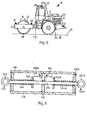
- FIG. 5 shows a construction machine 10 in the form of a vibration roller with driver's cab-12. At least one sensor is provided on each side of the construction machine 10 and responds to the floor surface approximately in the contact plane 14 of the construction machine 10.
- a sensor 16 contains an optical transmitter part 18 and a photoelectric receiver part 20, which are arranged on both sides of a roller body 22 on a roller frame 24, so that the sensor 16 responds to the floor surface in a region 26 at the level of the roller body contact line.
- a corresponding receiver part 20A can cooperate with the transmitter part 18 on the upper longitudinal beam 28.
- a transmitter part 30 and a receiver part 32 can form a sensor 34 which responds to the ground surface in an area 36 in the extension of the wheel contact lines.
- Such a sensor e.g. the sensor 16 is shown in Fig. 3.
- the transmitter part 18 has a cylindrical housing 38.
- a light bulb 42 with a straight filament 44 is seated in one end wall 40 of the housing 38.
- the filament 44 is imaged in a plane 50 as a filament image 52 by a first optical imaging system in the form of a lens 46 with the optical axis 48.
- a transparent cover 56 is arranged in front of the slit diaphragm 54.
- the receiver part 20 also has a cylindrical housing 58.
- a selenium barrier photo element 60 or another active photoelectric component with a receiver surface is provided which corresponds in size and position to the position of the helix 44 in the housing 38.
- a region 66 in the plane 50 is imaged on the photoelectric receiver 60 by a second optical imaging system in the form of a lens 62 with an optical axis 64.
- the spiral image 52 and the region 66 are shown rotated by 90 ° in the paper plane in FIG. 3. In fact, both lie in the plane 50.
- a slot diaphragm 68 is likewise arranged in the housing 58.
- the housing 58 is closed off by a transparent housing cover 70.
- transmitter part 18 and receiver part 20 form a V-shaped beam path. If a remitting surface, that is to say the floor surface, is located in plane 50, then a real image of the helical image generated by first imaging system 46 is generated by second imaging system 62 in plane of photoelectric receiver 60.
- the spiral image 52 and the area 66 detected by the photoelectric receiver 60 overlap only partially in the plane 50. If the remitting floor surface lies below the plane 50, the overlap rapidly decreases, so that the photoelectric Receiver then no longer delivers a signal. On the other hand, if the floor surface is above level 50, the overlap increases. The signal at the photoelectric receiver 60 is therefore retained. The sensor 16 thus responds to a falling surface by the absence of the receiver signal. However, it does not yet provide an error signal if the floor surface rises slightly above level 50. The sensor 16 with the transmitter part 18 and the receiver part 20 is arranged so that the plane 50 corresponds approximately to the contact plane 14.
- the light source ie the incandescent lamp 42
- the light source is modulated with an alternating frequency. This can be done in such a way that a square wave voltage of five to ten Hertz is applied to the connection terminals 72 of the incandescent lamp 42.
- the photoelectric receiver 60 then receives, in addition to a constant light component and a light intensity modulated by the movement of the construction machine 10 and the non-uniform remission of the floor surface, a component that corresponds to the alternating frequency of the light source is modulated.
- the output signal of the photoelectric receiver 60 appears at output terminals 74. In order to separate this alternating light component of the receiver signal from the constant light component and the other interference components, as shown in FIG.
- the receiver signal is connected to a ring modulator 76 which is controlled with the alternating frequency , with which the light source is modulated, that is to say with the square-wave voltage which is present at the terminals 72 of the incandescent lamp 42.
- the ring modulator 76 contains four diodes 78, 80, 82 and 84, which are arranged in the same direction in a bridge.
- the receiver signal lies over an input transformer 86 - at two diametrically opposite points of the bridge, while the control signal, that is, the square wave voltage, is present between the two other corner points of the bridge via an input transformer 88.
- An output voltage becomes between the center taps 90, 92 of the input transformer 86 and 88 tapped.
- RC element consisting of a resistor 94 and a capacitor 96 for smoothing the ring modulator output signal.
- the DC voltage at the capacitor 96 of the RC element is for
- Noise suppression connected via a diode 98 to an output 100 to which a resistor 102 is connected in parallel.
- the circuit described represents a correlation circuit that delivers an output signal when the photoelectric receiver 60. Via the helical pattern 52 delivers an alternating signal with the alternating frequency of the incandescent lamp 42., I.e. if the sensor 16 or 34 in the contact plane 14 of the construction machine 10 or recorded above this level of the surface of the soil. The signal from the sensor 16 or 34 disappears when the ground surface touches the Areas 26 or 36 drop noticeably below the contact plane 14 of the construction machine.
- the output signals of the various sensors 16, 34 ... are at inputs 104 of an AND gate 106. If one of these output signals is omitted, the output signal at the output 108 of the AND gate 106 goes into the logic state "0". This state at output 108 represents the "error signal".
- an optical or acoustic warning signal can be triggered by the error signal.
- the construction machine can be stopped by the error signal.
- a restart device which can be actuated by a separate key is provided, by means of which at least the travel drive of the construction machine 10 which has been shut down by the error signal can be switched on again.
- the output signal of the AND gate 106 negated by an inverter 110 switches on an optical or acoustic warning device via a relay 112.
- the negated output signal of the AND gate 106 also switches off the vibrating device via a switching element 114.
- the error signal from output 108 is present at an input of an EXCLUSIVE OR gate 116.
- a voltage is present at the other input of the EXCLUSIVE-OR gate 116 via a contact 118, which can be actuated in the closing sense by the key of the restart device.
- the output signal of the EXCLUSIVE-OR gate 116 controls a relay 122 via an inverter 120, by means of which the construction machine can be switched off.
- the EXCLUSIVE-OR gate 116 supplies a signal at its output if and only if a signal appears at the output of the AND gate 1 06 and the contact 118 of the restart device is open or the output signal at the output 108 of the AND gate 106 "0 "and contact 118 is closed.
- the normal case is that the contact 118 is open and at all.
- Inputs 104 of the AND gate 106 have sensor signals so that the output 108 of the AND gate 106 is in the "L" state.
- the EXCLUSIVE-OR gate 116 supplies the signal "L” at its output, which is negated by the inverter 120 to "0". Relay 122 has dropped out and the construction machine is operating.
- the contact 118 can be closed by the restart device. As a result, the output of the EXCLUSIVE-OR gate 116 becomes "L" again. Relay 122 drops out and puts the construction machine back into operation.
- a separate key can be provided, which is expediently provided by a supervisor. Person or the operator's safety officer should be kept in custody.
- the EXCLUSIVE-OR gate 116 also ensures that the construction machine cannot be operated with the contact 118 permanently closed. In this case, the signal "L" would normally be present at both inputs of the EXCLUSIVE-OR gate 116, so that the construction machine would be stopped.
- the vibration device is in any case stopped when an error signal occurs at the output 108, even if the drive of the construction machine is switched on again via the contact 118.
- the restart device allows the construction machine to be started up again and brought out of the danger zone.
- a device 124 can be provided at at least one location on the construction machine 10, which device allows a tensile force to be applied to the construction machine 10.
- the construction machine can then be connected to a second, parallel running construction machine by means of a rope, and this rope, e.g. by a suspended weight, a tensile force directed away from the slope edge is exerted on the tensile force sensor 146 or 146A of the device 124 or 124A. This responds when a predetermined minimum tractive force is reached.
- the traction force sensor can then be switched so that the error signal cannot be triggered by the sensors 16, 34 on the side of the construction machine 10 facing the slope when it has responded.
- This can be achieved by the circuit shown in FIG. 2.
- the output signals of the sensors 16, 34 on one side are applied to the inputs 126 of an AND gate 128.
- the output of the AND gate 128 and the output signal of the traction force sensor, which is symbolized here by a contact 130, are connected together. If the traction force sensor has responded, that is to say the contact 130 is closed, then no error signal occurs, even if a sensor signal on the AND gate 128 is omitted.
- a device 124 for attacking a tensile force with an associated sensor is preferably arranged for each side of the construction machine 10. It is particularly advantageous to combine two devices 124 and 124A for both machine sides in one construction, as shown in FIG. 6.
- the devices 124, 124A for attacking a tensile force each have an eye or a hook 132, 132A, which are connected to one another by a rod 134 extending transversely to the construction machine 10.
- the rod 134 is guided in a housing 136 fastened to the construction machine 10 in two end walls 138 and 138A and an intermediate wall 140.
- Disks 142, 142A are fastened on the rod 134 on both sides of the intermediate wall 140 at a distance from one another.
- a prestressed compression spring 144, 144A is arranged between each end wall 138, 138A and the adjacent disk 142, 142A.
- the tensile force sensors are formed by switches 146, 146A, which can be actuated by the disks 142A and 142 when they approach the intermediate wall 140.
- the tensile force sensors are represented by the contact 130 and a contact 130A.
- the sensor signals from the sensors on the side facing away from the device 132A are present at inputs 126A of an AND gate 128A.
- the sensor signal via the switch 130A and the output of the AND gate 128A are also connected together.
- the interconnected signals are present at the two inputs of an AND gate 148, the output 108 'of which corresponds to the output 108 of FIG. 1.
- the rest of the circuit is the same as in FIG. 1
- the individual parts of the device 124, 124A, their attachment to the construction machine 10 and the traction rope leading to the second construction machine are designed in such a strength that the required holding forces are transmitted with sufficient security when the construction machine 10 slips over the edge of the slope.
Landscapes
- Engineering & Computer Science (AREA)
- Mechanical Engineering (AREA)
- Chemical & Material Sciences (AREA)
- Combustion & Propulsion (AREA)
- Transportation (AREA)
- Human Computer Interaction (AREA)
- Architecture (AREA)
- Civil Engineering (AREA)
- Structural Engineering (AREA)
- Component Parts Of Construction Machinery (AREA)
- Jib Cranes (AREA)
Abstract
Description
Die Erfindung betrifft eine Sicherheitsvorrichtung an Baumaschinen.The invention relates to a safety device on construction machines.
Bei Baumaschinen wie Vibrationswalzen o.dgl. können schwerwiegende Unfälle dadurch entstehen, daß die Baumaschine über eine Kante, beispielsweise einer Böschung, hinausfährt oder so nahe an die Kante heranfährt, daß das Erdreich abrutscht. Die Baumaschine stürzt dann über die Böschung o.dgl. ab, was zu schwerwiegenden Sach- und Personenschäden führen kann. Das ist besonders kritisch bei Baumaschinen mit Fahrerstand, bei denen der Maschinenführer auf der Maschine sitzt und mit dieser abstürzt. Weiterhin ist dieses Problem kritisch bei Vibrationswalzen. Wenn eine solche Walze zu nahe an eine Kante heranfährt, dann begünstigt die Vibration ein Abrutschen des Erdreichs.In construction machines such as vibratory rollers or the like. Serious accidents can result from the construction machine moving over an edge, for example an embankment, or moving so close to the edge that the soil slides. The construction machine then falls over the slope or the like. which can lead to serious property damage and personal injury. This is particularly critical for construction machines with a driver's platform, where the machine operator sits on the machine and crashes with it. This problem is also critical in vibratory rollers. If such a roller comes too close to an edge, then the vibration promotes slipping of the soil.
Der Erfindung liegt die Aufgabe zu Grunde, Gefahrensituationen, die durch Heranfahren der Baumaschine an eine Kante entstehen können, zu vermeiden.The invention is based on the object of avoiding dangerous situations which can arise as the construction machine approaches an edge.
Erfindungsgemäß wird diese Aufgabe dadurch gelöst, daß
- (a) auf jeder Seite der Baumaschine ein Fühler vorgesehen ist, der auf die Bodenoberfläche etwa in der Aufstandsebene der Baumaschine anspricht, und
- (b) durch jeden der Fühler ein Fehlersignal auslösbar ist, wenn der Fühler keine Bodenoberfläche erfaßt.
- (a) a sensor is provided on each side of the construction machine, which sensor responds to the floor surface approximately in the contact plane of the construction machine, and
- (b) an error signal can be triggered by each of the sensors if the sensor does not detect a floor surface.
Durch das Fehlersignal kann ein optisches oder akustisches Warnsignal auslösbar sein. Es kann aber auch die Baumaschine durch das Fehlersignal stillsetzbar sein. Dadurch wird der Maschinenführer vor einer Gefahrensituation gewarnt oder das Heranfahren der Baumaschine an eine Kante überhaupt verhindert.An optical or acoustic warning signal can be triggered by the error signal. However, the construction machine can also be stopped by the error signal. This warns the machine operator of a dangerous situation or prevents the construction machine from approaching an edge at all.
Weitere Ausgestaltungen der Erfindung sind Gegenstand der Unteransprüche 4 bis 17.Further embodiments of the invention are the subject of dependent claims 4 to 17.
Ein Ausführungsbeispiel der Erfindung ist nachstehend unter Bezugnahme auf die zugehörigen Zeichnungen näher - erläutert:
- Fig. 1 ist ein logisches Schaltbild und zeigt die Verknüpfung der Fühlersignale zu einem Fehlersignal und die dadurch ausgelösten Schaltvorgänge sowie eine Wiederstartvor- richtung.
- Fig. 2 zeigt eine abgewandelte Ausführung des UND-Glieds bei der Schaltung von Fig. 1 mit Zugkraftfühlern, die auf seitliche Zugkräfte ansprechen,
- Fig. 3 zeigt den Aufbau eines photoelektrischen, auf Bodenoberfläche ansprechenden Fühlers,
- Fig. 4 ist ein Schaltbild und zeigt die Verarbeitung des Empfängersignals des photoelektrischen Fühlers zur Erzeugung eines Fühlersignals,
- Fig. 5 zeigt eine Seitenansicht einer Baumaschine in Form einer Vibrationswalze und veranschaulicht die Möglichkeiten der Anordnung der Fühler,
- Fig. 6 zeigt eine Einrichtung, welche das Ausüben seitlicher Zugkräfte auf die Baumaschine gestattet, die ein Abstürzen verhindern, und welche Zugkraftfühler enthält, die mit.der Schaltung von Fig. 1 zusammenwirken.
- 1 is a logical circuit diagram and shows the linking of the sensor signals to an error signal and the switching processes triggered thereby, as well as a restart device.
- FIG. 2 shows a modified version of the AND gate in the circuit of FIG. 1 with tensile force sensors which respond to lateral tensile forces,
- 3 shows the construction of a photoelectric sensor responding to the ground surface,
- 4 is a circuit diagram showing the processing of the receiver signal of the photoelectric sensor to generate a sensor signal,
- 5 shows a side view of a construction machine in the form of a vibrating roller and illustrates the possibilities for arranging the sensors,
- Fig. 6 shows a device which allows lateral tensile forces to be exerted on the construction machine, which prevent falling, and which contains tensile force sensors which cooperate with the circuit of Fig. 1.
In Fig. 5 ist eine Baumaschine 10 in Gestalt einer Vibrationswalze mit Fahrerstand-12 dargestellt. Auf jeder Seite der Baumaschine 10 ist wenigstens ein Fühler vorgesehen, der auf Bodenoberfläche etwa in der Aufstandsebene 14 der Baumaschine 10 anspricht. Ein Fühler 16 enthält einen optischen Senderteil 18 und einen photoelektrischen Empfängerteil 20, die beiderseits eines Walzenkörpers 22 auf einem Walzenrahmen 24 angeordnet sind, so daß der Fühler 16 auf Bodenoberfläche in einem Bereich 26 in Höhe der Walzenkörperaufstandslinie anspricht. Statt des Empfängerteils 20 kann ein entsprechendes Empfängerteil 20A am oberen Kabinenlängsholm 28 mit dem Senderteil 18 zusammenwirken.5 shows a
Ein Senderteil 30 und ein Empfängerteil 32 können einen Fühler 34 bilden, der auf Bodenoberfläche in einem Bereich 36 in der Verlängerung der Radaufstandslinien anspricht.A
Ein solcher Fühler, z.B. der Fühler 16,ist in Fig. 3 dargestellt.Such a sensor, e.g. the
Der Senderteil 18 weist ein zylindrisches Gehäuse 38 auf. In der einen Stirnwand 40 des Gehäuses 38 sitzt eine Glühlampe 42 mit einer geraden Wendel 44. Die Wendel-44 wird durch ein erstes optisches Abbildungssystem in Form einer Linse 46 mit der optischen Achse 48 in einer Ebene 50 als Wendelbild 52 abgebildet. Auf der der Glühlampe 42 gegenüberliegenden Stirnseite des Gehäuses 38 sitzt eine Schlitzblende 54, die parallel zu der Wendelachse verläuft. Vor der Schlitzblende 54 ist eine durchsichtige Abdeckung 56 angeordnet.The
Der Empfängerteil 20 weist ebenfalls ein zylindrisches Gehäuse 58 auf. An der einen Stirnseite des Gehäuses 58 ist ein Selen-Sperrschichtphotoelement 60 oder ein anderes aktives photoelektrisches Bauelement mit einer Empfängerfläche vorgesehen, die nach Größe und Lage der Position der Wendel 44 im Gehäuse 38 entspricht. Durch ein zweites optisches Abbildungssystem in Form einer Linse 62 mit einer optischen Achse 64 wird ein Bereich 66 in der Ebene 50 auf den photoelektrischen Empfänger 60 abgebildet. Der Anschaulichkeit halber sind in Fig. 3 das Wendelbild 52 und der Bereich 66 um 90° verdreht in der Papierebene dargestellt. Tatsächlich liegen beide in der Ebene 50. An dem dem Empfänger 60 abgewandten Ende ist in dem Gehäuse 58 ebenfalls eine Schlitzblende 68 angeordnet. Das Gehäuse 58 ist durch eine durchsichtige Gehäuseabdeckung 70 abgeschlossen.The
Wie aus Fig. 3 ersichtlich ist, bilden Senderteil 18 und Empfängerteil 20 einen V-förmigen Strahlengang. Wenn sich in der Ebene 50 eine remittierende Oberfläche, also die Bodenoberfläche befindet, dann wird durch das zweite Abbildungssystem 62 in der Ebene des photoelektrischen Empfängers 60 ein reelles Bild des von dem ersten Abbildungssystem 46 erzeugten Wendelbilds erzeugt.As can be seen from FIG. 3,
Wie aus Fig. 3 ersichtlich ist, überlappen sich in der Ebene 50 das Wendelbild 52 und der vom photoelektrischen -Empfänger 60 erfaßte Bereich 66 nur teilweise,Liegt die remittierende Bodenoberfläche unter der Ebene 50, so nimmt die Überlappung schnell ab, so daß der photoelektrische Empfänger dann kein Signal mehr-liefert. Liegt dagegen die Bodenoberfläche oberhalb der Ebene 50, so nimmt die Überlappung zu. Das Signal am photoelektrischen Empfänger 60 bleibt daher erhalten. Der Fühler 16 spricht somit durch Wegfall des Empfängersignals auf eine abfallende Flächean. Er liefert jedoch noch kein Fehlersignal, wenn sich die Bodenoberfläche etwas über die Ebene 50 erhebt. Der Fühler 16 mit dem Senderteil 18 und dem Empfängerteil 20 wird so angeordnet, daß die Ebene 50 etwa der Aufstandsebene 14 entspricht.As can be seen from FIG. 3, the
Um den Einfluß von Fremdlicht auszuschalten, ist die Lichtquelle, also die Glühlampe 42 mit einer Wechselfrequenz moduliert. Das kann in der Weise geschehen, daß an die Anschlußklemmen 72 der Glühlampe 42 eine Rechteckspannung von fünf bis zehn Hertz gelegt wird. Der photoelektrische Empfänger 60 erhält dann neben einem Gleichlichtanteil und einer durch die Fahrt der Baumaschine 10 sowie die ungleichmäßige Remission der Bodenoberfläche modulierten Lichtintensität auch einen Anteil, der mit der Wechselfrequenz der Lichtquelle moduliert ist. Das Ausgangssignal des photoelektrischen Empfängers 60 erscheint an Ausgangsklemmen 74. Um diesen Wechsellichtanteil des Empfängersignals von der Gleichlichtkomponente und den übrigen Störkomponenten zu trennen, ist, wie in Fig. 4 dargestellt ist, das Empfängersignal auf einen Ringmodulator 76 geschaltet, der mit der Wechselfrequenz gesteuert ist, mit der die Lichtquelle moduliert wird, also mit der Rechteckspannung, die an den Klemmen 72 der Glühlampe 42 anliegt. Der Ringmodulator 76 enthält.vier Dioden 78, 80, 82 und 84, die gleichsinnig in einer Brücke angeordnet sind. Das Empfängersignal liegt über einem Eingangsübertrager 86 - an zwei diametral gegenüberliegenden Punkten der Brücke, während das Steuersignal, also die Rechteckspannung über einen Eingangsübertrager 88 zwischen den beiden anderen Eckpunkten der Brücke anliegt..Eine Ausgangsspannung wird zwischen den Mittenanzapfungen 90, 92 der Eingangsüber- trager 86 und 88 abgegriffen.In order to switch off the influence of extraneous light, the light source, ie the
Am Ausgang des Ringmodulators 76 liegt ein RC-Glied bestehend aus einem Widerstand 94 und einem Kondensator 96 zur Glättung des Ringmodulator-Ausgangssignals. Die Gleichspannung am.Kondensator 96 des RC-Gliedes ist zurAt the output of the
Rauschunterdrückung über eine Diode 98 auf einen Ausgang 100 geschaltet, zu dem.ein Widerstand 102 parallel liegt.Noise suppression connected via a
Die beschriebene Schaltung stellt eine Korrelationsschaltung dar, die ein Ausgangssignal liefert, wenn der photoelektrische Empfänger 60.über das Wendelbild 52 ,ein Wechselsignal mit der Wechselfrequenz der Glühlampe 42.liefert, wenn also der Fühler 16 oder 34 in der Aufstandsebene 14 der Baumaschine 10 oder oberhalb dieser Ebene Bodenoberfläche erfaßt. Das Signal des Fühlers 16 oder 34 fällt weg, wenn die Bodenoberfläche an den Bereichen 26 oder 36 merklich unter die Aufstandsebene 14 der Baumaschine absinkt.The circuit described represents a correlation circuit that delivers an output signal when the
Die Ausgangssignale der verschiedenen Fühler 16,34... liegen an Eingängen 104 eines UND-Glieds 106. Wenn eines dieser Ausgangssignale wegfällt, so geht das Ausgangssignal am Ausgang 108 des UND-Glieds 106 in den logischen Zustand "0". Dieser Zustand am Ausgang 108 stellt das "Fehlersignal" dar. Bei der in Fig. 1 dargestellten Ausführungsform ist durch das Fehlersignal ein optisches oder akustisches Warnsignal auslösbar. Weiterhin ist die Baumaschine durch das Fehlersignal stillsetzbar. Es ist eine durch einen gesonderten Schlüssel betätigbare Wiederstartvorrichtung vorgesehen, durch welche wenigstens der Fahrantrieb der durch das Fehlersignal stillgesetzten Baumaschine 10 wieder einschaltbar ist.The output signals of the
Zu diesem Zweck schaltet das durch einen Inverter 110 negierte Ausgangssignal des UND-Glieds 106 über ein Relais 112 eine optische oder akustische Warnvorrichtung ein. Bei einer mit einer Rüttelvorrichtung arbeitenden Baumaschine, beispielsweise der in Fig. 5 dargestellten Vibrationswalze, schaltet das negierte Ausgangssignal des UND-Glieds 106 außerdem über ein Schaltglied 114 die Rüttelvorrichtung ab.For this purpose, the output signal of the AND
Weiterhin liegt das Fehlersignal vom Ausgang 108 an einem Eingang eines EXCLUSIV-ODER-Glieds 116 an. An dem anderen Eingang des EXCLUSIV-ODER-Glieds 116 liegt eine Spannung über einen Kontakt 118 an, der durch den Schlüssel der Wiederstartvorrichtung im schließenden Sinne betätigbar ist. Das Ausgangssignal des EXCLUSIV-ODER-Glieds 116 steuert über einen Inverter 120 ein Relais 122 an, durch welches die Baumaschine ausschaltbar ist.Furthermore, the error signal from
Das EXLUSIV-ODER-Glied 116 liefert genau dann ein Signal an seinem Ausgang, wenn entweder ein Signal am Ausgang des UND-Glied 106 erscheint und der Kontakt 118 der Wiederstartvorrichtung geöffnet ist oder das Ausgangssignal am Ausgang 108 des UND-Glieds 106 "0" und der Kontakt 118 geschlossen ist. Der Normalfall ist, daß der Kontakt 118 geöffnet ist und.an sämtlichen . Eingängen 104 des UND-Glieds 106 Fühlersignale anliegen, so daß der Ausgang 108 des UND-Glieds 106 im Zustand "L" ist. In diesem Falle liefert das EXCLUSIV-ODER-Glied 116 das Signal "L" an seinem Ausgang, welches durch den Inverter 120 zu "0" negiert wird. Das Relais 122 ist abgefallen, und die Baumaschine ist in Betrieb. Fällt eines der Fühlersignale an den Eingängen 104 aus, so erscheint am Ausgang 108 des UND-Glieds 106 das Fehlersignal "0". Es liegt jetzt an beiden Eingängen des EXCLUSIV-ODER-Glieds 116 kein Signal, d..h. das Signal "0" an, so daß dessen Ausgang "0" wird. Dieses Signal wird zu "L" negiert und bewirkt ein Anziehen des Relais 122, wodurch die Baumaschine stillgesetzt wird.The EXCLUSIVE-
Durch die Wiederstartvorrichtung kann der Kontakt 118 geschlossen werden. Dadurch wird der Ausgang des EXCLUSIV-ODER-Glieds 116 wieder "L". Das Relais 122 fällt ab und setzt die Baumaschine wieder in Betrieb.The
Zum Betätigen der Wiederstartvorrichtung kann ein gesonderter Schlüssel vorgesehen werden, der zweckmäßigerweise von einer aufsichtführenden. Person oder dem Sicherheitsbeauftragten des Betreibers in Verwahrung genommen werden sollte. Das EXCLUSIV-ODER-Glied 116 stellt auch sicher, daß nicht etwa die Baumaschine bei ständig geschlosssenem Kontakt 118 betrieben werden kann. In diesem Falle würde normalerweise an beiden Eingängen des EXCLUSIV-ODER-Glieds 116 das Signal "L" anliegen, so daß die Baumaschine stillgesetzt würde.To actuate the restart device, a separate key can be provided, which is expediently provided by a supervisor. Person or the operator's safety officer should be kept in custody. The EXCLUSIVE-
Die Vibrationseinrichtung ist bei Auftreten eines Fehlersignals am Ausgang 108 auf jeden Fall stillgesetzt, auch wenn der Fahrantrieb der Baumaschine über den Kontakt 118 wieder eingeschaltet wird.The vibration device is in any case stopped when an error signal occurs at the
Die Wiederstartvorrichtung gestattet es, die Baumaschine wieder in Betrieb zu setzen und aus der Gefahrenzone herauszubringen.The restart device allows the construction machine to be started up again and brought out of the danger zone.
Für solche Fälle und um ein Arbeiten der Baumaschine auch längs einer Kante zu ermöglichen, kann an wenigstens einer Stelle der Baumaschine 10 eine Einrichtung 124 vorgesehen sein, welche den Angriff einer Zugkraft auf die Baumaschine 10 gestattet. Es kann dann beim Arbeiten längs einer Kante o. dgl. die Baumaschine über ein Seil mit einer zweiten, parallel fahrenden Baumaschine verbunden und über dieses Seil, z.B. durch ein angehängtes Gewicht, eine von der Böschungskante weg gerichtete Zugkraft auf den Zugkraftfühler 146 oder 146A der Einrichtung 124 oder 124A ausgeübt werden. Dieser spricht bei Erreichen einer vorgegebenen Mindest-Zugkraft an. Der Zugkraftfühler kann dann so geschaltet werden, daß das Fehlersignal von den Fühlern 16, 34 auf der der Böschung zugewandten Seite der Baumaschine 10 nicht auslösbar ist, wenn er angesprochen hat. Dies kann durch die in Fig. 2 dargestellte Schaltung erreicht werden. Dort liegen die Ausgangssignale der Fühler 16, 34 einer Seite an den Eingängen 126 eines UND-Gliedes 128 an. Der Ausgang des UND-Gliedes 128 und das Ausgangssignal des Zugkraftfühlers, das hier durch einen Kontakt 130 symbolisiert ist, sind zusammengeschaltet. Wenn der Zugkraftfühler angesprochen hat, der Kontakt 130 also geschlossen ist, dann tritt kein Fehlersignal auf, auch wenn ein Fühlersignal am UND-Glied 128 wegfällt.For such cases and in order to enable the construction machine to also work along an edge, a
Vorzugsweise ist für jede Seite der Baumaschine 10 eine Einrichtung 124 für den Angriff einer Zugkraft mit einem zugehörigen Fühler angeordnet. Besonders vorteilhaft ist es, zwei Einrichtungen 124 und 124A für beide Maschinen- seiten in einer Konstruktion zu vereinigen, wie in Fig. 6 dargestellt.A
Dort weisen die Einrichtungen 124, 124A für den Angriff einer Zugkraft je ein Auge oder einen Haken 132, 132A auf, die durch eine sich quer zu der Baumaschine 10 erstreckende Stange 134 miteinander verbunden sind. Die Stange 134 ist in einem an der Baumaschine 10 befestigten Gehäuse 136 in zwei Stirnwänden 138 und 138A und einer Zwischenwand 140 verschiebbar geführt. Auf der Stange 134 sind beiderseits der Zwischenwand 140 Scheiben 142, 142A im Abstand voneinander befestigt. Zwischen jeder Stirnwand 138, 138A und der benachbarten Scheibe 142, 142A ist eine vorgespannte Druckfeder 144, 144A angeordnet. Die Zugkraftfühler werden von Schaltern 146, 146A gebildet, die durch die Scheiben 142A bzw. 142 bei deren Annäherung an die Zwischenwand 140 betätigbar sind.There, the
In Fig. 2 sind die Zugkraftfühler durch den Kontakt 130 bzw. einen Kontakt 130A dargestellt. Die Fühlersignale von den Fühlern auf der der Einrichtung 132A abgewandten Seite liegen an Eingängen 126A eines UND-Gliedes 128A an. Das Fühlersignal über den Schalter 130A und der Ausgang des UND-Gliedes 128A sind ebenfalls zusammengeschaltet. Die zusammengeschalteten Signale liegen an den beiden Eingängen eines UND-Gliedes 148 an, dessen Ausgang 108' dem Ausgang 108 von Fig. 1 entspricht. Die übrige Schaltung ist die gleiche wie in Fig. 1In Fig. 2, the tensile force sensors are represented by the contact 130 and a
Wenn über das Auge 132 oder 132A eine Zugkraft auf die Baumaschine 10 ausgeübt wird, die den Zugkraftfühler auf einer Seite zum Ansprechen bringt, dann können die Fühlersignale auf der gegenüberliegenden Seite wegfallen, ohne daß dadurch die Baumaschine stillgesetzt wird. Wenn also beispielsweise der Kontakt 130 geschlossen ist, bleibt das Signal "L" an dem linken Eingang des UND-Glieds 148 erhalten, auch wenn ein Fühlersignal an einem Eingang 126 wegfällt. Der linke Eingang des UND-Glieds 148 liegt über den Kontakt 130 auf jeden Fall an Spannung. Die Fühlersignale auf der anderen Seite, wo die Zugkraft wirkt, müssen natürlich vorhanden sein. Der Kontakt 130A ist geöffnet, und es muß daher das UND-Glied 128A das Signal "L" liefern.If a tensile force is exerted on the
Die Einzelteile der Einrichtung 124, 124A, ihre Befestigung auf der Baumaschine 10 sowie das zur zweiten Baumaschine führende Zugseil sind in ihrer Festigkeit so ausgelegt, daß bei einem Abrutschen der Baumaschine 10 über die Böschungskante die erforderlichen Haltekräfte mit ausreichender Sicherheit übertragen werden.The individual parts of the
Claims (17)
Priority Applications (1)
| Application Number | Priority Date | Filing Date | Title |
|---|---|---|---|
| AT81106857T ATE18027T1 (en) | 1980-11-26 | 1981-09-02 | SAFETY DEVICE ON CONSTRUCTION MACHINERY. |
Applications Claiming Priority (2)
| Application Number | Priority Date | Filing Date | Title |
|---|---|---|---|
| DE3044485 | 1980-11-26 | ||
| DE19803044485 DE3044485A1 (en) | 1980-11-26 | 1980-11-26 | SAFETY DEVICE ON CONSTRUCTION MACHINERY |
Publications (3)
| Publication Number | Publication Date |
|---|---|
| EP0052702A2 true EP0052702A2 (en) | 1982-06-02 |
| EP0052702A3 EP0052702A3 (en) | 1984-02-29 |
| EP0052702B1 EP0052702B1 (en) | 1986-02-19 |
Family
ID=6117603
Family Applications (1)
| Application Number | Title | Priority Date | Filing Date |
|---|---|---|---|
| EP81106857A Expired EP0052702B1 (en) | 1980-11-26 | 1981-09-02 | Safety device for construction machines |
Country Status (3)
| Country | Link |
|---|---|
| EP (1) | EP0052702B1 (en) |
| AT (1) | ATE18027T1 (en) |
| DE (2) | DE3044485A1 (en) |
Cited By (3)
| Publication number | Priority date | Publication date | Assignee | Title |
|---|---|---|---|---|
| EP0195463A3 (en) * | 1985-03-11 | 1988-03-16 | Applied Power Inc. | Hydraulic master-slave cylinder clutch with safety system to assure positive clutch actuation |
| EP2021730A4 (en) * | 2006-05-12 | 2009-06-17 | Conplant Pty Ltd | Tilting alarm for a mobile machine |
| US20230287635A1 (en) * | 2022-03-11 | 2023-09-14 | Caterpillar Paving Products Inc. | Method and system for operating compaction machines |
Citations (3)
| Publication number | Priority date | Publication date | Assignee | Title |
|---|---|---|---|---|
| DE579545C (en) | 1933-06-28 | Buckau R Wolf Akt Ges Maschf | Automatic fall protection for heavy caterpillar vehicles, wi? Er, depositors and similar devices that discharge at the edge of embankments | |
| FR2289954A1 (en) | 1974-10-24 | 1976-05-28 | Inst Mek Mashin Akadem | OPTICAL DEVICE FOR AUTOMATIC GEARBOX CONTROL SYSTEM USING A LUMINOUS CONTRAST PROGRAM |
| FR2352692A1 (en) | 1976-05-25 | 1977-12-23 | Morin Roy Georges | Alarm for overturning of agricultural tractor - with detector for angle of vehicle body position |
-
1980
- 1980-11-26 DE DE19803044485 patent/DE3044485A1/en not_active Ceased
-
1981
- 1981-09-02 DE DE8181106857T patent/DE3173809D1/en not_active Expired
- 1981-09-02 AT AT81106857T patent/ATE18027T1/en not_active IP Right Cessation
- 1981-09-02 EP EP81106857A patent/EP0052702B1/en not_active Expired
Patent Citations (3)
| Publication number | Priority date | Publication date | Assignee | Title |
|---|---|---|---|---|
| DE579545C (en) | 1933-06-28 | Buckau R Wolf Akt Ges Maschf | Automatic fall protection for heavy caterpillar vehicles, wi? Er, depositors and similar devices that discharge at the edge of embankments | |
| FR2289954A1 (en) | 1974-10-24 | 1976-05-28 | Inst Mek Mashin Akadem | OPTICAL DEVICE FOR AUTOMATIC GEARBOX CONTROL SYSTEM USING A LUMINOUS CONTRAST PROGRAM |
| FR2352692A1 (en) | 1976-05-25 | 1977-12-23 | Morin Roy Georges | Alarm for overturning of agricultural tractor - with detector for angle of vehicle body position |
Cited By (3)
| Publication number | Priority date | Publication date | Assignee | Title |
|---|---|---|---|---|
| EP0195463A3 (en) * | 1985-03-11 | 1988-03-16 | Applied Power Inc. | Hydraulic master-slave cylinder clutch with safety system to assure positive clutch actuation |
| EP2021730A4 (en) * | 2006-05-12 | 2009-06-17 | Conplant Pty Ltd | Tilting alarm for a mobile machine |
| US20230287635A1 (en) * | 2022-03-11 | 2023-09-14 | Caterpillar Paving Products Inc. | Method and system for operating compaction machines |
Also Published As
| Publication number | Publication date |
|---|---|
| DE3173809D1 (en) | 1986-03-27 |
| EP0052702B1 (en) | 1986-02-19 |
| EP0052702A3 (en) | 1984-02-29 |
| DE3044485A1 (en) | 1982-06-03 |
| ATE18027T1 (en) | 1986-03-15 |
Similar Documents
| Publication | Publication Date | Title |
|---|---|---|
| DE69023492T2 (en) | MACHINE PROXIMITY SENSOR. | |
| DE10026305A1 (en) | Opto-electronic device for monitoring protection region, has image determination unit which picks-up planar or spatial image of monitoring regions that lay near and outside the protection region | |
| DE3717771A1 (en) | CAPACITIVE SAFETY ARRANGEMENT | |
| DE2406369C2 (en) | Tank level control device | |
| EP3339715A1 (en) | Access protection system | |
| EP1443343B1 (en) | Optical sensor with a plurality of switching outputs | |
| DE3908273C1 (en) | Self-test device for a scanning light probe | |
| DE102019131774A1 (en) | Monitoring system for robots and robot systems | |
| DE10055689B4 (en) | Method for operating an optical triangulation light grid | |
| DE20103828U1 (en) | Security device for monitoring a passage | |
| EP3415804B1 (en) | Safety device | |
| EP1408273A2 (en) | Protection device for monitoring a protected zone related to a moving element | |
| DE3536472A1 (en) | DEPTH MEASURING DEVICE FOR CRANE SYSTEMS | |
| DE1905016C3 (en) | Visibility measuring device | |
| EP0052702A2 (en) | Safety device for construction machines | |
| DE19745493C2 (en) | Device for securing the rear area of a motor vehicle | |
| EP1826589A1 (en) | Optical sensor for monitoring a protection zone | |
| EP1110901B1 (en) | Escalator roller degradation monitor device | |
| DE202021104977U1 (en) | monitoring device | |
| DE3131490C2 (en) | ||
| EP0049794A2 (en) | Electronic switching device operated without contact | |
| EP3862617B1 (en) | Device for securing a hazardous area | |
| DE9416314U1 (en) | smoke detector | |
| DE4233285A1 (en) | Moving yarn break sensor - uses reflected optical signal from yarn modulated to separate it from ambient frequencies | |
| DE102006008805B4 (en) | Optical sensor and method for monitoring a protection zone by means of an optical sensor |
Legal Events
| Date | Code | Title | Description |
|---|---|---|---|
| PUAI | Public reference made under article 153(3) epc to a published international application that has entered the european phase |
Free format text: ORIGINAL CODE: 0009012 |
|
| AK | Designated contracting states |
Designated state(s): AT DE FR GB IT SE |
|
| PUAL | Search report despatched |
Free format text: ORIGINAL CODE: 0009013 |
|
| AK | Designated contracting states |
Designated state(s): AT DE FR GB IT SE |
|
| 17P | Request for examination filed |
Effective date: 19840210 |
|
| GRAA | (expected) grant |
Free format text: ORIGINAL CODE: 0009210 |
|
| RAP1 | Party data changed (applicant data changed or rights of an application transferred) |
Owner name: CASE VIBROMAX GMBH & CO. KG |
|
| AK | Designated contracting states |
Designated state(s): AT DE FR GB IT SE |
|
| REF | Corresponds to: |
Ref document number: 18027 Country of ref document: AT Date of ref document: 19860315 Kind code of ref document: T |
|
| REF | Corresponds to: |
Ref document number: 3173809 Country of ref document: DE Date of ref document: 19860327 |
|
| ITF | It: translation for a ep patent filed | ||
| ET | Fr: translation filed | ||
| PG25 | Lapsed in a contracting state [announced via postgrant information from national office to epo] |
Ref country code: AT Effective date: 19860902 |
|
| PG25 | Lapsed in a contracting state [announced via postgrant information from national office to epo] |
Ref country code: SE Effective date: 19860903 |
|
| PLBE | No opposition filed within time limit |
Free format text: ORIGINAL CODE: 0009261 |
|
| STAA | Information on the status of an ep patent application or granted ep patent |
Free format text: STATUS: NO OPPOSITION FILED WITHIN TIME LIMIT |
|
| 26N | No opposition filed | ||
| PG25 | Lapsed in a contracting state [announced via postgrant information from national office to epo] |
Ref country code: FR Free format text: LAPSE BECAUSE OF NON-PAYMENT OF DUE FEES Effective date: 19870527 |
|
| GBPC | Gb: european patent ceased through non-payment of renewal fee | ||
| PG25 | Lapsed in a contracting state [announced via postgrant information from national office to epo] |
Ref country code: DE Effective date: 19870701 |
|
| REG | Reference to a national code |
Ref country code: FR Ref legal event code: ST |
|
| PG25 | Lapsed in a contracting state [announced via postgrant information from national office to epo] |
Ref country code: GB Effective date: 19881118 |
|
| EUG | Se: european patent has lapsed |
Ref document number: 81106857.6 Effective date: 19870812 |