EP3862617B1 - Dispositif de sécurisation d'une zone dangereuse - Google Patents
Dispositif de sécurisation d'une zone dangereuse Download PDFInfo
- Publication number
- EP3862617B1 EP3862617B1 EP20186107.7A EP20186107A EP3862617B1 EP 3862617 B1 EP3862617 B1 EP 3862617B1 EP 20186107 A EP20186107 A EP 20186107A EP 3862617 B1 EP3862617 B1 EP 3862617B1
- Authority
- EP
- European Patent Office
- Prior art keywords
- protective field
- optical sensor
- sensor
- control signal
- predetermined
- Prior art date
- Legal status (The legal status is an assumption and is not a legal conclusion. Google has not performed a legal analysis and makes no representation as to the accuracy of the status listed.)
- Active
Links
- 231100001261 hazardous Toxicity 0.000 title claims description 7
- 230000001681 protective effect Effects 0.000 claims description 95
- 230000003287 optical effect Effects 0.000 claims description 76
- 238000012544 monitoring process Methods 0.000 claims description 33
- 238000001514 detection method Methods 0.000 claims description 17
- 230000004913 activation Effects 0.000 claims description 15
- 230000001960 triggered effect Effects 0.000 claims description 4
- 230000011664 signaling Effects 0.000 claims description 2
- 230000006870 function Effects 0.000 description 16
- 238000011156 evaluation Methods 0.000 description 12
- 238000000034 method Methods 0.000 description 6
- 230000003213 activating effect Effects 0.000 description 3
- 230000007257 malfunction Effects 0.000 description 3
- 230000000295 complement effect Effects 0.000 description 2
- 238000005516 engineering process Methods 0.000 description 2
- 238000005259 measurement Methods 0.000 description 2
- 238000004891 communication Methods 0.000 description 1
- 238000011161 development Methods 0.000 description 1
- 238000005286 illumination Methods 0.000 description 1
- 230000000737 periodic effect Effects 0.000 description 1
- 238000011144 upstream manufacturing Methods 0.000 description 1
Images


Classifications
-
- F—MECHANICAL ENGINEERING; LIGHTING; HEATING; WEAPONS; BLASTING
- F16—ENGINEERING ELEMENTS AND UNITS; GENERAL MEASURES FOR PRODUCING AND MAINTAINING EFFECTIVE FUNCTIONING OF MACHINES OR INSTALLATIONS; THERMAL INSULATION IN GENERAL
- F16P—SAFETY DEVICES IN GENERAL; SAFETY DEVICES FOR PRESSES
- F16P3/00—Safety devices acting in conjunction with the control or operation of a machine; Control arrangements requiring the simultaneous use of two or more parts of the body
- F16P3/12—Safety devices acting in conjunction with the control or operation of a machine; Control arrangements requiring the simultaneous use of two or more parts of the body with means, e.g. feelers, which in case of the presence of a body part of a person in or near the danger zone influence the control or operation of the machine
- F16P3/14—Safety devices acting in conjunction with the control or operation of a machine; Control arrangements requiring the simultaneous use of two or more parts of the body with means, e.g. feelers, which in case of the presence of a body part of a person in or near the danger zone influence the control or operation of the machine the means being photocells or other devices sensitive without mechanical contact
- F16P3/142—Safety devices acting in conjunction with the control or operation of a machine; Control arrangements requiring the simultaneous use of two or more parts of the body with means, e.g. feelers, which in case of the presence of a body part of a person in or near the danger zone influence the control or operation of the machine the means being photocells or other devices sensitive without mechanical contact using image capturing devices
-
- F—MECHANICAL ENGINEERING; LIGHTING; HEATING; WEAPONS; BLASTING
- F16—ENGINEERING ELEMENTS AND UNITS; GENERAL MEASURES FOR PRODUCING AND MAINTAINING EFFECTIVE FUNCTIONING OF MACHINES OR INSTALLATIONS; THERMAL INSULATION IN GENERAL
- F16P—SAFETY DEVICES IN GENERAL; SAFETY DEVICES FOR PRESSES
- F16P3/00—Safety devices acting in conjunction with the control or operation of a machine; Control arrangements requiring the simultaneous use of two or more parts of the body
- F16P3/12—Safety devices acting in conjunction with the control or operation of a machine; Control arrangements requiring the simultaneous use of two or more parts of the body with means, e.g. feelers, which in case of the presence of a body part of a person in or near the danger zone influence the control or operation of the machine
- F16P3/14—Safety devices acting in conjunction with the control or operation of a machine; Control arrangements requiring the simultaneous use of two or more parts of the body with means, e.g. feelers, which in case of the presence of a body part of a person in or near the danger zone influence the control or operation of the machine the means being photocells or other devices sensitive without mechanical contact
- F16P3/144—Safety devices acting in conjunction with the control or operation of a machine; Control arrangements requiring the simultaneous use of two or more parts of the body with means, e.g. feelers, which in case of the presence of a body part of a person in or near the danger zone influence the control or operation of the machine the means being photocells or other devices sensitive without mechanical contact using light grids
Definitions
- the invention relates to a device for securing a danger area.
- Such devices can be provided to secure danger areas on stationary machines or systems, whereby a danger area in which dangerous movements are carried out by the machine or system must be secured.
- Such devices can be used to secure the apron on vehicles in order to provide collision protection for the vehicle.
- distance-measuring optical sensors to monitor danger areas, which can be designed, for example, as an area distance sensor, that is, as a scanning distance sensor.
- a binary switching signal with a corresponding switching state is then generated in the optical sensor. If the switching signal assumes the switching state "object present" when an object is detected, a safety function is triggered, which creates a safe operating state that avoids endangering people.
- the safety function can consist of shutting down the machine or system.
- the safety function may be to stop the vehicle.
- the DE 103 12 972 B3 relates to an optical sensor with a distance sensor element, consisting of a transmitter that emits transmitted light beams and a receiver that receives received light beams.
- the transmitted light beams are deflected using a deflection unit so that they periodically sweep over a monitoring area.
- an evaluation unit several protective fields are stored as parameters, each of which forms predetermined areas of the monitoring area, with at least one of the stored protective fields being able to be activated.
- an object detection signal is generated in the evaluation unit, which indicates whether an object is within the activated protective field or not.
- a communication interface is connected to the evaluation unit, via which activation signals for activating the protective field can be read.
- the EP 3 330 740 A1 relates to a method for detecting objects in a detection area and includes an optical sensor with a sensor unit that generates sensor signals and an evaluation unit in which the sensor signals are evaluated.
- a protective field within the detection area and delimited by a protective field boundary is specified in the evaluation unit.
- An object detection signal is generated in the evaluation unit when an intrusion of an inadmissible object into the protective field is registered based on the sensor signals.
- this part of the protective field boundary is replaced by the contour of the permissible object structure via a part of the protective field boundary into the protective field using the sensor unit in the evaluation unit.
- the invention is based on the object of providing a device of the type mentioned at the outset, by means of which improved security of danger areas is made possible.
- the invention relates to a device for securing a danger area, with at least one distance-measuring optical sensor, which is designed for object detection in a flat or spatial detection area.
- object monitoring is carried out with the optical sensor within at least one predetermined protective field.
- Object monitoring in the specified protective field can be deactivated using a control signal.
- at least one new protective field is generated, within which the optical sensor continues object monitoring.
- the new protective field is deactivated for a specified activation time. After the activation time has expired, the optical sensor carries out object monitoring again within the specified protective field.
- the basic idea of the invention is therefore to use the control signal to specifically change the object monitoring carried out with the optical sensor and to adapt it to changing boundary conditions.
- the control signal read into the optical sensor by an external unit can, in particular, signal a fault, for example a process fault in a system to be monitored.
- the monitoring function of the device according to the invention is generally designed in such a way that a switching signal is generated in the optical sensor, the switching states of which indicate whether an object is in the protective field or not.
- a safety function is triggered with a switching signal signaling an object in the protective field.
- the safety function can consist of shutting down a system monitored with the optical sensor that could pose a risk to people.
- object monitoring is carried out in a predetermined protective field during regular operation. This means that safety-critical objects are detected in the protective field, with such object detection leading to the generation of a switching signal and, depending on this, to the triggering of a safety function.
- the specified protective field is dimensioned so that permissible objects that do not pose a hazard do not penetrate the specified protective field.
- the optical sensor is then used to monitor a danger area on a conveyor unit on which conveyed goods are fed to the system.
- the conveyed goods represent permissible objects that do not pose any hazards.
- control signal is generated by the control of the conveyor unit.
- the specified protective field is then dimensioned so that the conveyed goods do not protrude into this specified protective field.
- the specified protective field is adapted to the maximum size of the goods to be conveyed.
- control signal is activated and the object monitoring within the specified protective field is thereby deactivated, the state of the current object monitoring in the specified protective field is used.
- the optical sensor If an object intervention is currently registered in the specified protective field, the optical sensor generates the switching signal that leads to the generation of the safety function.
- the new protective field can in principle be smaller than the specified protective field, but this is advantageously larger.
- the new protective field is dimensioned so that the object present in the danger area does not protrude into the new protective field and is therefore treated as a permissible object.
- the contour of the object present in the danger area is advantageously taught in as a reference contour.
- the limit of the new protective field is determined depending on the reference contour.
- control of the conveyor unit can, for example, generate the control signal if the conveyor unit is stopped due to a malfunction or the like.
- a permissible object i.e. a conveyed item
- the new protective field is adapted to this permissible object in such a way that the permissible object is left out of the new protective field, this does not lead to an unnecessary generation of a switching signal and therefore not to an unnecessary triggering of the safety function.
- the new protective field is activated for a predetermined activation time. After the activation time has expired, the optical sensor carries out object monitoring again within the specified protective field.
- the control signal is therefore only used to temporarily change the operating mode of the optical sensor, advantageously only as long as there is a malfunction that leads to the resolution of the control signal.
- the activation time expediently corresponds to the duration of activation of the control signal.
- the control signal thus immediately specifies the activation time.
- the optical sensor is an area distance sensor or a camera sensor.
- the optical sensor is also advantageously a safety sensor.
- optical sensor and also the entire device can be used in the field of security technology, particularly in the field of personal protection.
- the optical sensor designed as a safety sensor has a fail-safe structure for this purpose. This is advantageously achieved in that the optical sensor has a redundant evaluation unit, in particular in the form of two cyclically monitoring computer units.
- the device according to the invention has a multiple arrangement of optical sensors.
- One or more protective fields can be monitored using an optical sensor.
- the Figures 1 to 3 show exemplary embodiments of distance-measuring optical sensors 1, the distance measurements advantageously being carried out using a pulse transit time method or a phase measuring method.
- Figure 1 shows an exemplary embodiment of an optical sensor 1 in the form of an area distance sensor, that is, a scanning distance sensor.
- the optical sensor 1 has a transmitter 3 that emits light beams 2 and a receiver 4 that receives light beams 2.
- the transmitter 3 emits light beams 2 in the form of light pulses. 1 shows, the light rays 2 are reflected on an object 5 to be detected, with the corresponding light transit time of the light pulses to the object 5 and back to the optical sensor 1 being evaluated for the distance determination.
- the sensor components of the optical sensors 1 are integrated in a housing 6, with the transmitter 3 and the receiver 4 having a upstream receiving optics 7 are arranged stationary in the housing 6.
- object detection is carried out in a flat detection area in that the light beams 2 are periodically deflected by means of a deflection unit 8.
- the deflection unit 8 is motor-driven and includes an angle mirror 9 which can be rotated about an axis of rotation D and on which the light beams 2 are deflected.
- Figure 2 shows a variant of the area distance sensor according to Figure 1 .
- the periodic deflection of the light beams 2 takes place in that the transmitter 3 and the receiver 4 are arranged in a measuring head 10 which can be rotated about an axis of rotation D, the measuring head 10 being rotatably mounted on a base 11.
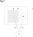
- Figure 3 shows the sensor components of an optical sensor 1 designed as a camera sensor.
- This optical sensor 1 has an illumination unit 12 that emits light beams 2 and an image sensor 13 as a receiver 4, which can be designed in the form of a CCD or CMOS array with a matrix-shaped arrangement of receiving elements 14 can.
- each optical sensor 1 has an evaluation unit, not shown, in which the received signals from the receiver 4 are evaluated.
- the evaluation is carried out in such a way that protective field monitoring is carried out and, depending on an object intervention in a protective field, a binary switching signal is generated, the switching states of which indicate whether an object 5 is present in the protective field 20 or not. If an object 5 is present in the protective field 20, the corresponding switching state of the switching signal triggers a safety function in such a way that a dangerous machine is stopped so that no more danger can arise from it.
- the optical sensors 1 according to Figures 1 to 3 designed as a safety sensor and have one fail-safe structure, which could be implemented, for example, by a redundant evaluation unit in the form of two computer units that cyclically monitor each other.
- FIGS 4 and 5 show a first exemplary embodiment of the device 15 according to the invention, in which an optical sensor 1 according to Figures 1 to 3 is generally used, in which case the optical sensor 1 is designed as a surface distance sensor.
- the device 15 is used to secure access to a dangerous machine (not shown). In order to be able to carry out work processes with the machine, this material 16 must be fed.
- a conveyor unit in the form of a conveyor belt 17 is provided, which is protected on the side by fences 18.
- the material to be conveyed 16 is conveyed on pallets 19 on the conveyor belt 17.
- the conveyor belt 17 is controlled with a control, not shown. In regular operation, the conveyor belt 17 is moved via the control at its predetermined, preferably constant, speed.
- the optical sensor 1 is arranged above the conveyor belt 17. In regular operation, the optical sensor 1 monitors a protective field within a predetermined protective field 20, which is oriented in the vertical direction and thus perpendicular to the surface of the conveyor belt 17.
- the specified protective field 20 is based on the maximum size of the conveyed goods, shown in Figure 4 , adjusted. This ensures that all conveyed goods can pass the optical sensor 1 and be fed to the machine as non-hazardous permissible objects 5 without violating the specified protective field 20 and therefore without triggering the safety function. Additional intrusion by safety-critical objects 5, in particular people, However, this leads to a violation of the protective field and triggering of the safety function.
- a control signal is generated in the controller and is read into the optical sensor 1.
- a new protective field 21 is generated as an extension of the predetermined protective field 20 by a learning process.
- the new protective field 21 is also oriented in a vertical direction.
- the contour of the conveyed material 16 currently present in the reception area of the optical sensor 1 is recorded as a permissible object 5 with the optical sensor 1 and saved as a reference contour.
- the new protective field 21 depicted from this represents an extension of the predetermined protective field 20 in such a way that the conveyed material 16 present in the detection area of the optical sensor 1 is precisely left out with the new protective field 21.
- the object monitoring within the predetermined protective field 20 is deactivated in the optical sensor 1 and object monitoring is thus carried out in the new protective field 21.
- This new object monitoring only takes place temporarily during a specified activation time.
- the activation time advantageously corresponds to the period of time during which the control signal is activated, that is to say for the period of time when the conveying stops.
- the new protective field 21 is adapted to the contour of the conveyed material 16 present in the detection area of the optical sensor 1, it does not protrude into the new protective field 21 and does not lead to the safety function being triggered unnecessarily.
- another object 5 in particular a person, who is in the detection range of the optical sensor 1 leads to a violation of the new protective field 21 and thus to the triggering of the safety function.
- the optical sensor 1 After the activation time has elapsed, the optical sensor 1 returns to an old monitoring mode, that is, monitoring takes place again within the specified protective field 20.
- the Figures 6 and 7 show a variant of the embodiment Figures 4 and 5 .
- two optical sensors 1 are provided.
- two predetermined partial protective fields 20a, b are monitored with the optical sensors 1, which complement the predetermined protective field 20 ( Figure 6 ). If the control signal is activated, new partial protective fields 21a, b are determined for the two optical sensors 1, which complement the new protective fields 21, in which the currently existing conveyed material 16 is again adapted ( Figure 7 ).
- the switching signals generated in the optical sensors 1, which report object interventions in the individual partial protective fields, are brought together in a higher-level evaluation unit (not shown), preferably logically linked.
- the resulting switching signal is then used to control the machine and, in particular, to trigger the safety function. Otherwise, monitoring takes place in accordance with the embodiment Figures 4 and 5 .
Landscapes
- Engineering & Computer Science (AREA)
- General Engineering & Computer Science (AREA)
- Mechanical Engineering (AREA)
- Geophysics And Detection Of Objects (AREA)
Claims (15)
- Dispositif (15) de sécurisation d'une zone dangereuse, comportant au moins un capteur optique de mesure de distance (1) conçu pour la détection d'objets dans une zone de détection plane ou spatiale, ladite surveillance d'objets étant effectuée dans au moins un champ de protection prédéterminé (20) afin de sécuriser la zone dangereuse avec le capteur optique (1), caractérisé en ce que la surveillance d'objets dans le champ de protection prédéterminé (20) peut être désactivée à l'aide d'un signal de commande, et en ce que, en fonction d'un objet (5) présent dans la zone dangereuse, au moins un nouveau champ de protection (21) est généré, à l'intérieur duquel le capteur optique (1) poursuit ladite surveillance d'objet, et en ce que le nouveau champ de protection (21) est désactivé pendant un temps d'activation prédéterminé, et en ce que, une fois le temps d'activation écoulé, le capteur optique (1) effectue à nouveau ladite surveillance d'objet à l'intérieur du champ de protection prédéterminé (20).
- Dispositif (15) selon la revendication 1, caractérisé en ce que la surveillance des objets n'est désactivée au moyen du signal de commande que s'il n'y a pas d'intervention d'un objet dans le champ de protection prédéterminé (21).
- Dispositif (15) selon l'une des revendications 1 ou 2, caractérisé en ce que le nouveau champ de protection (21) est plus grand que le champ de protection prédéterminé (20).
- Dispositif (15) selon l'une des revendications 1 à 3, caractérisé en ce que la taille du nouveau champ de protection (20) est adaptée à la taille du produit transporté (16) présent dans la zone dangereuse.
- Dispositif (15) selon l'une des revendications 1 à 4, caractérisé en ce que, lorsque le signal de commande est activé au moyen du capteur optique (1), le contour du matériau transporté (16) présent dans la zone dangereuse est appris comme contour de référence, et en ce que la limite du nouveau champ de protection (21) est déterminée en fonction du contour de référence.
- Dispositif (15) selon l'une des revendications 1 à 5, caractérisé en ce que le temps d'activation correspond à la durée de l'activation du signal de commande.
- Dispositif (15) selon l'une des revendications 1 à 6, caractérisé en ce que le signal de commande est généré par un contrôleur externe.
- Dispositif (15) selon la revendication 7, caractérisé en ce que le système de commande contrôle une unité de transport sur laquelle est transporté le matériau (16) détecté par le capteur optique (1).
- Dispositif (15) selon l'une des revendications 1 à 8, caractérisé en ce qu'un signal de commutation est généré dans le capteur optique (1), dont les états de commutation indiquent si un objet (5) se trouve ou non dans le champ de protection (20).
- Dispositif (15) selon la revendication 9, caractérisé par le fait qu'une fonction de sécurité est déclenchée par un signal de commutation signalant un objet (5) présent dans le champ de protection (20).
- Dispositif (15) selon l'une des revendications 1 à 10, caractérisé en ce que le capteur optique (1) est un capteur de distance de zone ou un capteur de caméra.
- Dispositif (15) selon l'une des revendications 1 à 11, caractérisé en ce que le capteur optique (1) est un capteur de sécurité.
- Dispositif (15) selon l'une des revendications 1 à 12, caractérisé par un agencement multiple de capteurs optiques (1).
- Dispositif (15) selon l'une des revendications 1 à 13, caractérisé par le fait qu'un ou plusieurs champs de protection (20, 21) sont surveillés à l'aide d'un capteur optique (1).
- Dispositif (15) selon l'une des revendications 1 à 14, caractérisé par la réalisation d'un protecteur d'accès à l'aide de ce dispositif.
Applications Claiming Priority (1)
| Application Number | Priority Date | Filing Date | Title |
|---|---|---|---|
| DE202020100644.4U DE202020100644U1 (de) | 2020-02-06 | 2020-02-06 | Vorrichtung zur Sicherung eines Gefahrenbereichs |
Publications (2)
| Publication Number | Publication Date |
|---|---|
| EP3862617A1 EP3862617A1 (fr) | 2021-08-11 |
| EP3862617B1 true EP3862617B1 (fr) | 2023-10-25 |
Family
ID=71661652
Family Applications (1)
| Application Number | Title | Priority Date | Filing Date |
|---|---|---|---|
| EP20186107.7A Active EP3862617B1 (fr) | 2020-02-06 | 2020-07-16 | Dispositif de sécurisation d'une zone dangereuse |
Country Status (2)
| Country | Link |
|---|---|
| EP (1) | EP3862617B1 (fr) |
| DE (1) | DE202020100644U1 (fr) |
Family Cites Families (7)
| Publication number | Priority date | Publication date | Assignee | Title |
|---|---|---|---|---|
| DE10312972B3 (de) * | 2003-03-24 | 2004-06-24 | Leuze Lumiflex Gmbh + Co. Kg | Optischer Sensor |
| EP2386876B1 (fr) * | 2010-05-04 | 2013-07-10 | Sick AG | Capteur de sécurité optoélectronique mesurant l'éloignement et procédé de surveillance d'une zone de surveillance |
| EP2395372B1 (fr) * | 2010-06-09 | 2013-10-09 | Sick AG | Scanner de sécurité |
| DE102015215234A1 (de) * | 2015-08-10 | 2017-02-16 | Fraunhofer-Gesellschaft zur Förderung der angewandten Forschung e.V. | Einrichtung zum Absichern eines Sicherheitsbereichs um mindestens eine automatisch arbeitende Maschine |
| DE102015220495A1 (de) * | 2015-10-21 | 2017-04-27 | Kuka Roboter Gmbh | Schutzfeldanpassung eines Manipulatorsystems |
| EP3330740B1 (fr) * | 2016-11-30 | 2021-09-08 | Leuze electronic GmbH + Co KG | Procédé de détection d'objets dans une zone de détection |
| EP3640522B1 (fr) * | 2018-10-17 | 2023-01-04 | Leuze electronic GmbH + Co. KG | Dispositif de surveillance |
-
2020
- 2020-02-06 DE DE202020100644.4U patent/DE202020100644U1/de active Active
- 2020-07-16 EP EP20186107.7A patent/EP3862617B1/fr active Active
Also Published As
| Publication number | Publication date |
|---|---|
| EP3862617A1 (fr) | 2021-08-11 |
| DE202020100644U1 (de) | 2021-05-07 |
Similar Documents
| Publication | Publication Date | Title |
|---|---|---|
| EP2470407B1 (fr) | Dispositif de surveillance et procédé de surveillance d'une zone d'entrée ou de sortie d'une ouverture d'accès d'un véhicule à une partie d'un édifice | |
| EP3339715B1 (fr) | Système de protection d'accès | |
| EP1046925B1 (fr) | Dispositif optoélectronique | |
| EP2306063B1 (fr) | Capteur de sécurité | |
| DE102005030829C5 (de) | Verfahren zum Betrieb eines Lichtgitters und Lichtgitter | |
| DE102008004941B4 (de) | Sicherheitsanordnung und Verfahren | |
| EP1443343B1 (fr) | Détecteur optique avec plusiers sorties de commutation | |
| DE10312972B3 (de) | Optischer Sensor | |
| EP3217195B1 (fr) | Capteur optique | |
| DE202020102721U1 (de) | Überwachungseinrichtung | |
| EP3415804B1 (fr) | Dispositif de sécurité | |
| EP3633413B1 (fr) | Dispositif de sécurité | |
| EP2395372B1 (fr) | Scanner de sécurité | |
| EP1837586B1 (fr) | Dispositif de surveillance d'une zone dangereuse près d'une machine | |
| EP3640522B1 (fr) | Dispositif de surveillance | |
| EP3862617B1 (fr) | Dispositif de sécurisation d'une zone dangereuse | |
| EP1826589A1 (fr) | Capteur optique destiné à la surveillance d'une zone de sécurité | |
| EP3882505B1 (fr) | Dispositif de surveillance et procédé de fonctionnement d'un dispositif de surveillance | |
| DE202020103157U1 (de) | Überwachungseinrichtung | |
| EP4119982B1 (fr) | Dispositif de surveillance et procédé de fonctionnement d'un dispositif de surveillance | |
| EP3627033B1 (fr) | Dispositif de sécurisation d'une zone à risque d'une installation | |
| EP3575666A1 (fr) | Dispositif de sécurisation d'une zone à risque d'une installation | |
| EP4354010A1 (fr) | Dispositif de surveillance | |
| EP3910227B1 (fr) | Dispositif de surveillance et procédé de fonctionnement d'un dispositif de surveillance | |
| EP3945238B1 (fr) | Dispositif de surveillance et procédé de fonctionnement d'un dispositif de surveillance |
Legal Events
| Date | Code | Title | Description |
|---|---|---|---|
| PUAI | Public reference made under article 153(3) epc to a published international application that has entered the european phase |
Free format text: ORIGINAL CODE: 0009012 |
|
| STAA | Information on the status of an ep patent application or granted ep patent |
Free format text: STATUS: REQUEST FOR EXAMINATION WAS MADE |
|
| 17P | Request for examination filed |
Effective date: 20210125 |
|
| AK | Designated contracting states |
Kind code of ref document: A1 Designated state(s): AL AT BE BG CH CY CZ DE DK EE ES FI FR GB GR HR HU IE IS IT LI LT LU LV MC MK MT NL NO PL PT RO RS SE SI SK SM TR |
|
| GRAP | Despatch of communication of intention to grant a patent |
Free format text: ORIGINAL CODE: EPIDOSNIGR1 |
|
| STAA | Information on the status of an ep patent application or granted ep patent |
Free format text: STATUS: GRANT OF PATENT IS INTENDED |
|
| INTG | Intention to grant announced |
Effective date: 20230731 |
|
| GRAS | Grant fee paid |
Free format text: ORIGINAL CODE: EPIDOSNIGR3 |
|
| GRAA | (expected) grant |
Free format text: ORIGINAL CODE: 0009210 |
|
| STAA | Information on the status of an ep patent application or granted ep patent |
Free format text: STATUS: THE PATENT HAS BEEN GRANTED |
|
| AK | Designated contracting states |
Kind code of ref document: B1 Designated state(s): AL AT BE BG CH CY CZ DE DK EE ES FI FR GB GR HR HU IE IS IT LI LT LU LV MC MK MT NL NO PL PT RO RS SE SI SK SM TR |
|
| REG | Reference to a national code |
Ref country code: GB Ref legal event code: FG4D Free format text: NOT ENGLISH |
|
| REG | Reference to a national code |
Ref country code: CH Ref legal event code: EP |
|
| REG | Reference to a national code |
Ref country code: DE Ref legal event code: R096 Ref document number: 502020005744 Country of ref document: DE |
|
| REG | Reference to a national code |
Ref country code: IE Ref legal event code: FG4D Free format text: LANGUAGE OF EP DOCUMENT: GERMAN |
|
| REG | Reference to a national code |
Ref country code: LT Ref legal event code: MG9D |
|
| REG | Reference to a national code |
Ref country code: NL Ref legal event code: MP Effective date: 20231025 |
|
| PG25 | Lapsed in a contracting state [announced via postgrant information from national office to epo] |
Ref country code: NL Free format text: LAPSE BECAUSE OF FAILURE TO SUBMIT A TRANSLATION OF THE DESCRIPTION OR TO PAY THE FEE WITHIN THE PRESCRIBED TIME-LIMIT Effective date: 20231025 |
|
| PG25 | Lapsed in a contracting state [announced via postgrant information from national office to epo] |
Ref country code: GR Free format text: LAPSE BECAUSE OF FAILURE TO SUBMIT A TRANSLATION OF THE DESCRIPTION OR TO PAY THE FEE WITHIN THE PRESCRIBED TIME-LIMIT Effective date: 20240126 |
|
| PG25 | Lapsed in a contracting state [announced via postgrant information from national office to epo] |
Ref country code: IS Free format text: LAPSE BECAUSE OF FAILURE TO SUBMIT A TRANSLATION OF THE DESCRIPTION OR TO PAY THE FEE WITHIN THE PRESCRIBED TIME-LIMIT Effective date: 20240225 |
|
| PG25 | Lapsed in a contracting state [announced via postgrant information from national office to epo] |
Ref country code: LT Free format text: LAPSE BECAUSE OF FAILURE TO SUBMIT A TRANSLATION OF THE DESCRIPTION OR TO PAY THE FEE WITHIN THE PRESCRIBED TIME-LIMIT Effective date: 20231025 |
|
| PG25 | Lapsed in a contracting state [announced via postgrant information from national office to epo] |
Ref country code: ES Free format text: LAPSE BECAUSE OF FAILURE TO SUBMIT A TRANSLATION OF THE DESCRIPTION OR TO PAY THE FEE WITHIN THE PRESCRIBED TIME-LIMIT Effective date: 20231025 |
|
| PG25 | Lapsed in a contracting state [announced via postgrant information from national office to epo] |
Ref country code: LT Free format text: LAPSE BECAUSE OF FAILURE TO SUBMIT A TRANSLATION OF THE DESCRIPTION OR TO PAY THE FEE WITHIN THE PRESCRIBED TIME-LIMIT Effective date: 20231025 Ref country code: IS Free format text: LAPSE BECAUSE OF FAILURE TO SUBMIT A TRANSLATION OF THE DESCRIPTION OR TO PAY THE FEE WITHIN THE PRESCRIBED TIME-LIMIT Effective date: 20240225 Ref country code: GR Free format text: LAPSE BECAUSE OF FAILURE TO SUBMIT A TRANSLATION OF THE DESCRIPTION OR TO PAY THE FEE WITHIN THE PRESCRIBED TIME-LIMIT Effective date: 20240126 Ref country code: ES Free format text: LAPSE BECAUSE OF FAILURE TO SUBMIT A TRANSLATION OF THE DESCRIPTION OR TO PAY THE FEE WITHIN THE PRESCRIBED TIME-LIMIT Effective date: 20231025 Ref country code: BG Free format text: LAPSE BECAUSE OF FAILURE TO SUBMIT A TRANSLATION OF THE DESCRIPTION OR TO PAY THE FEE WITHIN THE PRESCRIBED TIME-LIMIT Effective date: 20240125 Ref country code: PT Free format text: LAPSE BECAUSE OF FAILURE TO SUBMIT A TRANSLATION OF THE DESCRIPTION OR TO PAY THE FEE WITHIN THE PRESCRIBED TIME-LIMIT Effective date: 20240226 |