EP0052371A2 - Vakuumschalter - Google Patents
Vakuumschalter Download PDFInfo
- Publication number
- EP0052371A2 EP0052371A2 EP81109720A EP81109720A EP0052371A2 EP 0052371 A2 EP0052371 A2 EP 0052371A2 EP 81109720 A EP81109720 A EP 81109720A EP 81109720 A EP81109720 A EP 81109720A EP 0052371 A2 EP0052371 A2 EP 0052371A2
- Authority
- EP
- European Patent Office
- Prior art keywords
- arc
- electrode
- main surface
- electrodes
- vacuum interrupter
- Prior art date
- Legal status (The legal status is an assumption and is not a legal conclusion. Google has not performed a legal analysis and makes no representation as to the accuracy of the status listed.)
- Granted
Links
Images

Classifications
-
- H—ELECTRICITY
- H01—ELECTRIC ELEMENTS
- H01H—ELECTRIC SWITCHES; RELAYS; SELECTORS; EMERGENCY PROTECTIVE DEVICES
- H01H33/00—High-tension or heavy-current switches with arc-extinguishing or arc-preventing means
- H01H33/60—Switches wherein the means for extinguishing or preventing the arc do not include separate means for obtaining or increasing flow of arc-extinguishing fluid
- H01H33/66—Vacuum switches
- H01H33/664—Contacts; Arc-extinguishing means, e.g. arcing rings
- H01H33/6644—Contacts; Arc-extinguishing means, e.g. arcing rings having coil-like electrical connections between contact rod and the proper contact
-
- H—ELECTRICITY
- H01—ELECTRIC ELEMENTS
- H01H—ELECTRIC SWITCHES; RELAYS; SELECTORS; EMERGENCY PROTECTIVE DEVICES
- H01H33/00—High-tension or heavy-current switches with arc-extinguishing or arc-preventing means
- H01H33/60—Switches wherein the means for extinguishing or preventing the arc do not include separate means for obtaining or increasing flow of arc-extinguishing fluid
- H01H33/66—Vacuum switches
- H01H33/664—Contacts; Arc-extinguishing means, e.g. arcing rings
- H01H33/6643—Contacts; Arc-extinguishing means, e.g. arcing rings having disc-shaped contacts subdivided in petal-like segments, e.g. by helical grooves
Definitions
- the present invention relates to an improved vacuum circuit breaker or interrupter in which arc electrodes are connected to the respective coil electrodes within a vacuum vessel to generate magentic fields parallel to one another to thereby eliminate arc triggered or occurred between the arc electrodes.
- a pair of opposing arc electrodes are provided in a cylindrical vacuum vessel, which electrodes are each mounted on its back side with a conductive rod. Normally, the arc electrode pair are being energized with a current in its contact or closed condition.
- the vacuum interrupter functions to break or separate the arc electrode pair from each other to prevent the damage of the motor. In this case, arc generated between the pair of arc electrodes must be eliminated as quickly as possible.
- U.S. Patent No. 4,196,327 and in British Patent No. 1,573,350 a vacuum interrupter of parallel magnetic field electrode type wherein axially parallel magnetic fields are applied to the generated arc so as to disperse the arc into a numerous number of thin fiber-like arc currents for elimination of the arc.
- coil electrodes electrically connect the respective rods at the tip ends thereof with the respective arc electrodes.
- the coil electrodes each comprises a plurality of arm sections extending radially from the rod through which a current supplied from the rod is passed, and a circumferential ring section for passing the currents coming from the arm sections into the ring section to generate axially parallel magentic fields.
- the circumferential ring section is electrically connected partly with the associated arc electrode.
- the arc electrode is formed with a plurality of slits which extend radially from the center of the arc electrode. The slits serve to reduce that area on the arc electrode where eddy currents induced by the parallel magnetic fields flow to thereby prevent the reduction of the magnetic fields.
- the arc electrodes according to the present invention are respectively provided on its back side (the face of the arc electrode opposite to a main surface portion on which the arc takes place) with a reinforcement member of an electric conductivity higher than the main surface portion, thus allowing a substantial reduction of the electric resistance of current paths in the arc electrode between the center and circumference thereof. Therefore, the arc current can flow from the center of the arc electrode uniformly into the conductive reinforcement member attached onto the circumferential portion thereof, whereby a higher interruption efficiency can be obtained for the vacuum interrupter.
- a vacuum interrupter 1 in accordance with an embodiment of the present invention, which includes a vacuum vessel 4 defined by a cylindrical insulating wall 2 and metallic end caps 3A, 3B sealing the wall at the both ends thereof, and a pair of stationary and movable electrode assemblied 5, 6 disposed within the vacuum vessel in separatable and contactable fashion from and with each other (i.e. to allow ON and OFF operations).
- a metallic bellows 9 is arranged between one of the rods 8 and the related end cap 3B so that the movable electrode assembly 6 is separatable and contactable from and with the mated stationary one 5.
- an intermediate metallic shield 10 is disposed between the both electrode assemblies 5 and 6 and the inner wall of the insulating cylinder 2.
- the conductive rod 7 is formed at its one end with a hollow portion 11 which receives a spacer 13 made of high electric resistance material such as statinless steel, and a stepped portion 12 which carries a coil electrode 15.
- This electrode 15 in turn is provded with integral arm sections 16 which extend radially outwardly from the rod 7, and with a circumferential ring-shaped section 17 which is connected integrally to the arm sections.
- the ring section 17 is also provided with a projected section 18.
- An arc electrode 20 is supported by the projection 18 and the spacer 13.
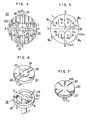
- the arc electrode 20 has a contact portion 22 at the central portion thereof and a main surface portion 21 continuously connected therewith.
- the contact portion 22 extrudes toward the opposed arc electrode of the mating electrode assembly 6.
- Main current paths 23 are formed on the main surface portion 21 as extended radially from the center 0 of the contact portion 22 to opposed circumferential points A and B on the coil electrode 15.
- a plurality of slits 24 extends from the main current paths 23 toward opposing circumferential points C and D which form right angles with respect to the points A and B, so as to define therebetween communication current paths 25 and six branching current paths 26 on the arc electrode 20.
- proper current blocking members may be provided which are made of high resistance material such as stainless steel and ceramic.
- the communication current paths 25 are connected at the both ends with the. projections 18 and at the central portion with the contact portion 22, so that the current coming from the coil electrode 15 is passed to the arc electrode 20 or the current coming from the arc electrode 20 is passed to the coil electrode 15.
- the branching current paths 26 are used to branch the currents coming from the main current paths 23.
- the main, communication and branching current paths 23, 25 and 26 are joined with proper solder to a conductive reinforcement member 27.
- the reinforcement member 27 is higher in electric conductivity than the main surface portion 21 and the contact portion 22. In other words, the electric resistance of the main surface portion 21 is greater than that of the reinforcement member 27.
- Conductive materials suitable for the main surface and contact portions 21 and 22 include Cu-Fe alloy and Cu-Co alloy. Proper conductive materials of the reinforcement 27 include Cu-Pb alloy and Cu-Bi alloy.
- the thickness T 1 of the reinformcement 27 is greater than the thickness T 2 of the main surface portion ( T 1 > T 2 ).
- a current I 1 entering into the coil electrode 15 from the rod 7 is first divided by the arm sections 16 equally into currents of 1/2 I 1 in opposite radial directions OA and OB, which divided currents of 1/2 I 1 are each further divided at points A and B by the ring section 17 into currents of 1/4 I 1 in circumferential directions, which currents of 1/4 I 1 are combined at points C and D respectively into currents of 1/2 I 1 to thus flow through the communication current path 25.
- arc 100 will take place on the contact portion 22.
- the arc 100 will be dispersed into a numerous stream of arc currents I 2 , as shown in Fig. 4.
- the arc currents I 2 will flow from the contact portion 22 to the conductive reinforcement member 27 via the current paths 23, 25 and 26.
- the arc currents I 2 will follow the similar route to the current I 1 , as illustrated in Fig. 5. Therefore, the arc currents I 2 will produce in the arc electrode 20 the parallel and same directioned magnetic fields H 1 ' to H 4 ' as in the coil electrode 15.
- the conductive reinforcement 27 is provided in this embodiment of the present.invention.
- the arc current 1 2 from the contact portion 22 will flow through the conductive reinforcement 27.
- the reinforcement 27 has an electric conductivity better than the main surface portion 21 in this embodiment such that the electric resistance of the current paths 23, 25 and 26 between the center 0 and the circumferential points A to D is smaller than that of the main surface portion 21. This will cause the arc current I 2 to flow equally through branching paths 26 from the main current paths 23, so that a high interruption efficiency can be obtained without the generation of local heat.
- heat generated in energization of the electrode assemblies may be eliminated or cooled by applying the reinforcement 27 onto the communication current paths 25 alone as shown in Fig. 6.
- the interruption function of the vacuum interrupter according to the present invention can be remarkably improved by employing the conductive reinforcement member having a better electric conductivity than the main surface portion of the arc electrode.
Landscapes
- High-Tension Arc-Extinguishing Switches Without Spraying Means (AREA)
Applications Claiming Priority (2)
| Application Number | Priority Date | Filing Date | Title |
|---|---|---|---|
| JP55160715A JPS5784530A (en) | 1980-11-17 | 1980-11-17 | Vacuum breaker |
| JP160715/80 | 1980-11-17 |
Publications (3)
| Publication Number | Publication Date |
|---|---|
| EP0052371A2 true EP0052371A2 (de) | 1982-05-26 |
| EP0052371A3 EP0052371A3 (en) | 1983-03-23 |
| EP0052371B1 EP0052371B1 (de) | 1985-06-05 |
Family
ID=15720897
Family Applications (1)
| Application Number | Title | Priority Date | Filing Date |
|---|---|---|---|
| EP81109720A Expired EP0052371B1 (de) | 1980-11-17 | 1981-11-16 | Vakuumschalter |
Country Status (4)
| Country | Link |
|---|---|
| US (1) | US4427857A (de) |
| EP (1) | EP0052371B1 (de) |
| JP (1) | JPS5784530A (de) |
| DE (1) | DE3170888D1 (de) |
Cited By (8)
| Publication number | Priority date | Publication date | Assignee | Title |
|---|---|---|---|---|
| DE3416368A1 (de) * | 1984-04-30 | 1984-12-13 | Ernst Prof. Dr.techn.habil. 1000 Berlin Slamecka | Vakuumschalter-kontaktanordnung |
| EP0118844A3 (de) * | 1983-03-04 | 1985-01-09 | Hitachi, Ltd. | Vakuumschalter und Herstellungsverfahren desselben |
| EP0104134A3 (de) * | 1982-09-21 | 1986-10-22 | Siemens Aktiengesellschaft | Vakuumschaltröhre mit Ringteil und diametralem Steg der Schaltstücke |
| WO1987006052A1 (fr) * | 1986-03-26 | 1987-10-08 | Siemens Aktiengesellschaft Berlin Und München | Systeme de contacts pour interrupteur a vide avec champ magnetique axial |
| EP0192251A3 (de) * | 1985-02-22 | 1989-02-22 | Mitsubishi Denki Kabushiki Kaisha | Elektrode eines Vakuumschalters |
| EP0371224A3 (en) * | 1988-11-24 | 1990-10-03 | Mitsubishi Denki Kabushiki Kaisha | Vacuum switch tube |
| EP0443236A1 (de) * | 1990-01-02 | 1991-08-28 | Cooper Industries, Inc. | Axialmagnetfeld-Vakuumschalter |
| DE4341714A1 (de) * | 1993-12-05 | 1994-04-28 | Slamecka Ernst | Vakuumschalter-Kontaktanordnung |
Families Citing this family (4)
| Publication number | Priority date | Publication date | Assignee | Title |
|---|---|---|---|---|
| DE3231593A1 (de) * | 1982-08-25 | 1984-03-01 | Siemens AG, 1000 Berlin und 8000 München | Kontaktanordnung fuer vakuumschalter |
| DE3840192A1 (de) * | 1987-12-02 | 1989-06-15 | Calor Emag Elektrizitaets Ag | Schaltkontaktanordnung |
| TW265452B (de) * | 1994-04-11 | 1995-12-11 | Hitachi Seisakusyo Kk | |
| US8319136B2 (en) * | 2010-06-29 | 2012-11-27 | Schneider Electric USA, Inc. | Arcing fault and arc flash protection system having a high-speed switch |
Family Cites Families (5)
| Publication number | Priority date | Publication date | Assignee | Title |
|---|---|---|---|---|
| JPS547945B2 (de) | 1973-06-30 | 1979-04-11 | ||
| FR2279216A1 (fr) * | 1973-09-10 | 1976-02-13 | Tokyo Shibaura Electric Co | Interrupteur a vide a champ magnetique |
| US3953698A (en) * | 1973-09-28 | 1976-04-27 | Siemens Aktiengesellschaft | Contact system for a vacuum switch |
| JPS58810B2 (ja) | 1976-12-06 | 1983-01-08 | 株式会社日立製作所 | 真空しや断器 |
| JPS5826132B2 (ja) * | 1978-11-22 | 1983-06-01 | 株式会社日立製作所 | 真空しや断器 |
-
1980
- 1980-11-17 JP JP55160715A patent/JPS5784530A/ja active Pending
-
1981
- 1981-11-10 US US06/319,985 patent/US4427857A/en not_active Expired - Fee Related
- 1981-11-16 EP EP81109720A patent/EP0052371B1/de not_active Expired
- 1981-11-16 DE DE8181109720T patent/DE3170888D1/de not_active Expired
Cited By (9)
| Publication number | Priority date | Publication date | Assignee | Title |
|---|---|---|---|---|
| EP0104134A3 (de) * | 1982-09-21 | 1986-10-22 | Siemens Aktiengesellschaft | Vakuumschaltröhre mit Ringteil und diametralem Steg der Schaltstücke |
| EP0118844A3 (de) * | 1983-03-04 | 1985-01-09 | Hitachi, Ltd. | Vakuumschalter und Herstellungsverfahren desselben |
| DE3416368A1 (de) * | 1984-04-30 | 1984-12-13 | Ernst Prof. Dr.techn.habil. 1000 Berlin Slamecka | Vakuumschalter-kontaktanordnung |
| EP0192251A3 (de) * | 1985-02-22 | 1989-02-22 | Mitsubishi Denki Kabushiki Kaisha | Elektrode eines Vakuumschalters |
| WO1987006052A1 (fr) * | 1986-03-26 | 1987-10-08 | Siemens Aktiengesellschaft Berlin Und München | Systeme de contacts pour interrupteur a vide avec champ magnetique axial |
| US4935588A (en) * | 1986-03-26 | 1990-06-19 | Siemens Aktiengesellschaft | Contact arrangement for vacuum switches with axial magnetic fields |
| EP0371224A3 (en) * | 1988-11-24 | 1990-10-03 | Mitsubishi Denki Kabushiki Kaisha | Vacuum switch tube |
| EP0443236A1 (de) * | 1990-01-02 | 1991-08-28 | Cooper Industries, Inc. | Axialmagnetfeld-Vakuumschalter |
| DE4341714A1 (de) * | 1993-12-05 | 1994-04-28 | Slamecka Ernst | Vakuumschalter-Kontaktanordnung |
Also Published As
| Publication number | Publication date |
|---|---|
| EP0052371B1 (de) | 1985-06-05 |
| JPS5784530A (en) | 1982-05-26 |
| DE3170888D1 (en) | 1985-07-11 |
| US4427857A (en) | 1984-01-24 |
| EP0052371A3 (en) | 1983-03-23 |
Similar Documents
| Publication | Publication Date | Title |
|---|---|---|
| US4704506A (en) | Vacuum interrupter | |
| US3946179A (en) | Vacuum interrupter | |
| US3280286A (en) | Vacuum-type circuit interrupter | |
| CA1224233A (en) | Vacuum interrupter | |
| US3469050A (en) | Arc rotating coil structure in vacuum circuit interrupters | |
| EP0329410B1 (de) | Vakuumschalter | |
| EP0597434B1 (de) | Vakuumschalter | |
| US4427857A (en) | Vacuum interrupter | |
| CA1077547A (en) | Vacuum type circuit interrupter with a contact having integral axial magnetic field means | |
| JPS58111231A (ja) | しや断器用真空バルブ | |
| US4336430A (en) | Vacuum interrupter | |
| JP3159827B2 (ja) | 真空遮断器、真空遮断器用電極およびその製作方法 | |
| US20060124600A1 (en) | Vacuum interrupter | |
| KR920006060B1 (ko) | 진공스위치관 | |
| EP0133368B2 (de) | Kontakt für Hochstromschalter | |
| US3225167A (en) | Vacuum circuit breaker with arc rotation contact means | |
| US4695689A (en) | Vacuum circuit breaker | |
| KR880002576B1 (ko) | 진공 차단기 | |
| US3591743A (en) | Vacuum-type circuit interrupter with flexible, weld-breaking contact structure | |
| US4855547A (en) | Vacuum interrupter | |
| JPS63304543A (ja) | 真空遮断器 | |
| KR910006238B1 (ko) | 진공 인터라프터(interrupter) | |
| JPH10321092A (ja) | 真空バルブの偏倚電極及びこの偏倚電極を用いた真空バルブ及びこの真空バルブを用いた真空遮断器 | |
| JPS639968Y2 (de) | ||
| US4760222A (en) | Vacuum circuit interrupter |
Legal Events
| Date | Code | Title | Description |
|---|---|---|---|
| PUAI | Public reference made under article 153(3) epc to a published international application that has entered the european phase |
Free format text: ORIGINAL CODE: 0009012 |
|
| AK | Designated contracting states |
Designated state(s): CH DE FR GB SE |
|
| PUAL | Search report despatched |
Free format text: ORIGINAL CODE: 0009013 |
|
| AK | Designated contracting states |
Designated state(s): CH DE FR GB LI SE |
|
| 17P | Request for examination filed |
Effective date: 19830208 |
|
| GRAA | (expected) grant |
Free format text: ORIGINAL CODE: 0009210 |
|
| AK | Designated contracting states |
Designated state(s): CH DE FR GB LI SE |
|
| REF | Corresponds to: |
Ref document number: 3170888 Country of ref document: DE Date of ref document: 19850711 |
|
| ET | Fr: translation filed | ||
| PLBE | No opposition filed within time limit |
Free format text: ORIGINAL CODE: 0009261 |
|
| STAA | Information on the status of an ep patent application or granted ep patent |
Free format text: STATUS: NO OPPOSITION FILED WITHIN TIME LIMIT |
|
| 26N | No opposition filed | ||
| PGFP | Annual fee paid to national office [announced via postgrant information from national office to epo] |
Ref country code: CH Payment date: 19920129 Year of fee payment: 11 |
|
| PGFP | Annual fee paid to national office [announced via postgrant information from national office to epo] |
Ref country code: FR Payment date: 19920918 Year of fee payment: 12 |
|
| PGFP | Annual fee paid to national office [announced via postgrant information from national office to epo] |
Ref country code: GB Payment date: 19920923 Year of fee payment: 12 |
|
| PGFP | Annual fee paid to national office [announced via postgrant information from national office to epo] |
Ref country code: SE Payment date: 19921005 Year of fee payment: 12 |
|
| PG25 | Lapsed in a contracting state [announced via postgrant information from national office to epo] |
Ref country code: SE Effective date: 19921117 |
|
| PG25 | Lapsed in a contracting state [announced via postgrant information from national office to epo] |
Ref country code: LI Effective date: 19921130 Ref country code: CH Effective date: 19921130 |
|
| PGFP | Annual fee paid to national office [announced via postgrant information from national office to epo] |
Ref country code: DE Payment date: 19921231 Year of fee payment: 12 |
|
| REG | Reference to a national code |
Ref country code: CH Ref legal event code: PL |
|
| PG25 | Lapsed in a contracting state [announced via postgrant information from national office to epo] |
Ref country code: GB Effective date: 19931116 |
|
| GBPC | Gb: european patent ceased through non-payment of renewal fee |
Effective date: 19931116 |
|
| PG25 | Lapsed in a contracting state [announced via postgrant information from national office to epo] |
Ref country code: FR Effective date: 19940729 |
|
| PG25 | Lapsed in a contracting state [announced via postgrant information from national office to epo] |
Ref country code: DE Effective date: 19940802 |
|
| REG | Reference to a national code |
Ref country code: FR Ref legal event code: ST |
|
| EUG | Se: european patent has lapsed |
Ref document number: 81109720.3 Effective date: 19930610 |