EP0052371A2 - Vacuum interrupter - Google Patents
Vacuum interrupter Download PDFInfo
- Publication number
- EP0052371A2 EP0052371A2 EP81109720A EP81109720A EP0052371A2 EP 0052371 A2 EP0052371 A2 EP 0052371A2 EP 81109720 A EP81109720 A EP 81109720A EP 81109720 A EP81109720 A EP 81109720A EP 0052371 A2 EP0052371 A2 EP 0052371A2
- Authority
- EP
- European Patent Office
- Prior art keywords
- arc
- electrode
- main surface
- electrodes
- vacuum interrupter
- Prior art date
- Legal status (The legal status is an assumption and is not a legal conclusion. Google has not performed a legal analysis and makes no representation as to the accuracy of the status listed.)
- Granted
Links
Images

Classifications
-
- H—ELECTRICITY
- H01—ELECTRIC ELEMENTS
- H01H—ELECTRIC SWITCHES; RELAYS; SELECTORS; EMERGENCY PROTECTIVE DEVICES
- H01H33/00—High-tension or heavy-current switches with arc-extinguishing or arc-preventing means
- H01H33/60—Switches wherein the means for extinguishing or preventing the arc do not include separate means for obtaining or increasing flow of arc-extinguishing fluid
- H01H33/66—Vacuum switches
- H01H33/664—Contacts; Arc-extinguishing means, e.g. arcing rings
- H01H33/6644—Contacts; Arc-extinguishing means, e.g. arcing rings having coil-like electrical connections between contact rod and the proper contact
-
- H—ELECTRICITY
- H01—ELECTRIC ELEMENTS
- H01H—ELECTRIC SWITCHES; RELAYS; SELECTORS; EMERGENCY PROTECTIVE DEVICES
- H01H33/00—High-tension or heavy-current switches with arc-extinguishing or arc-preventing means
- H01H33/60—Switches wherein the means for extinguishing or preventing the arc do not include separate means for obtaining or increasing flow of arc-extinguishing fluid
- H01H33/66—Vacuum switches
- H01H33/664—Contacts; Arc-extinguishing means, e.g. arcing rings
- H01H33/6643—Contacts; Arc-extinguishing means, e.g. arcing rings having disc-shaped contacts subdivided in petal-like segments, e.g. by helical grooves
Definitions
- the present invention relates to an improved vacuum circuit breaker or interrupter in which arc electrodes are connected to the respective coil electrodes within a vacuum vessel to generate magentic fields parallel to one another to thereby eliminate arc triggered or occurred between the arc electrodes.
- a pair of opposing arc electrodes are provided in a cylindrical vacuum vessel, which electrodes are each mounted on its back side with a conductive rod. Normally, the arc electrode pair are being energized with a current in its contact or closed condition.
- the vacuum interrupter functions to break or separate the arc electrode pair from each other to prevent the damage of the motor. In this case, arc generated between the pair of arc electrodes must be eliminated as quickly as possible.
- U.S. Patent No. 4,196,327 and in British Patent No. 1,573,350 a vacuum interrupter of parallel magnetic field electrode type wherein axially parallel magnetic fields are applied to the generated arc so as to disperse the arc into a numerous number of thin fiber-like arc currents for elimination of the arc.
- coil electrodes electrically connect the respective rods at the tip ends thereof with the respective arc electrodes.
- the coil electrodes each comprises a plurality of arm sections extending radially from the rod through which a current supplied from the rod is passed, and a circumferential ring section for passing the currents coming from the arm sections into the ring section to generate axially parallel magentic fields.
- the circumferential ring section is electrically connected partly with the associated arc electrode.
- the arc electrode is formed with a plurality of slits which extend radially from the center of the arc electrode. The slits serve to reduce that area on the arc electrode where eddy currents induced by the parallel magnetic fields flow to thereby prevent the reduction of the magnetic fields.
- the arc electrodes according to the present invention are respectively provided on its back side (the face of the arc electrode opposite to a main surface portion on which the arc takes place) with a reinforcement member of an electric conductivity higher than the main surface portion, thus allowing a substantial reduction of the electric resistance of current paths in the arc electrode between the center and circumference thereof. Therefore, the arc current can flow from the center of the arc electrode uniformly into the conductive reinforcement member attached onto the circumferential portion thereof, whereby a higher interruption efficiency can be obtained for the vacuum interrupter.
- a vacuum interrupter 1 in accordance with an embodiment of the present invention, which includes a vacuum vessel 4 defined by a cylindrical insulating wall 2 and metallic end caps 3A, 3B sealing the wall at the both ends thereof, and a pair of stationary and movable electrode assemblied 5, 6 disposed within the vacuum vessel in separatable and contactable fashion from and with each other (i.e. to allow ON and OFF operations).
- a metallic bellows 9 is arranged between one of the rods 8 and the related end cap 3B so that the movable electrode assembly 6 is separatable and contactable from and with the mated stationary one 5.
- an intermediate metallic shield 10 is disposed between the both electrode assemblies 5 and 6 and the inner wall of the insulating cylinder 2.
- the conductive rod 7 is formed at its one end with a hollow portion 11 which receives a spacer 13 made of high electric resistance material such as statinless steel, and a stepped portion 12 which carries a coil electrode 15.
- This electrode 15 in turn is provded with integral arm sections 16 which extend radially outwardly from the rod 7, and with a circumferential ring-shaped section 17 which is connected integrally to the arm sections.
- the ring section 17 is also provided with a projected section 18.
- An arc electrode 20 is supported by the projection 18 and the spacer 13.
- the arc electrode 20 has a contact portion 22 at the central portion thereof and a main surface portion 21 continuously connected therewith.
- the contact portion 22 extrudes toward the opposed arc electrode of the mating electrode assembly 6.
- Main current paths 23 are formed on the main surface portion 21 as extended radially from the center 0 of the contact portion 22 to opposed circumferential points A and B on the coil electrode 15.
- a plurality of slits 24 extends from the main current paths 23 toward opposing circumferential points C and D which form right angles with respect to the points A and B, so as to define therebetween communication current paths 25 and six branching current paths 26 on the arc electrode 20.
- proper current blocking members may be provided which are made of high resistance material such as stainless steel and ceramic.
- the communication current paths 25 are connected at the both ends with the. projections 18 and at the central portion with the contact portion 22, so that the current coming from the coil electrode 15 is passed to the arc electrode 20 or the current coming from the arc electrode 20 is passed to the coil electrode 15.
- the branching current paths 26 are used to branch the currents coming from the main current paths 23.
- the main, communication and branching current paths 23, 25 and 26 are joined with proper solder to a conductive reinforcement member 27.
- the reinforcement member 27 is higher in electric conductivity than the main surface portion 21 and the contact portion 22. In other words, the electric resistance of the main surface portion 21 is greater than that of the reinforcement member 27.
- Conductive materials suitable for the main surface and contact portions 21 and 22 include Cu-Fe alloy and Cu-Co alloy. Proper conductive materials of the reinforcement 27 include Cu-Pb alloy and Cu-Bi alloy.
- the thickness T 1 of the reinformcement 27 is greater than the thickness T 2 of the main surface portion ( T 1 > T 2 ).
- a current I 1 entering into the coil electrode 15 from the rod 7 is first divided by the arm sections 16 equally into currents of 1/2 I 1 in opposite radial directions OA and OB, which divided currents of 1/2 I 1 are each further divided at points A and B by the ring section 17 into currents of 1/4 I 1 in circumferential directions, which currents of 1/4 I 1 are combined at points C and D respectively into currents of 1/2 I 1 to thus flow through the communication current path 25.
- arc 100 will take place on the contact portion 22.
- the arc 100 will be dispersed into a numerous stream of arc currents I 2 , as shown in Fig. 4.
- the arc currents I 2 will flow from the contact portion 22 to the conductive reinforcement member 27 via the current paths 23, 25 and 26.
- the arc currents I 2 will follow the similar route to the current I 1 , as illustrated in Fig. 5. Therefore, the arc currents I 2 will produce in the arc electrode 20 the parallel and same directioned magnetic fields H 1 ' to H 4 ' as in the coil electrode 15.
- the conductive reinforcement 27 is provided in this embodiment of the present.invention.
- the arc current 1 2 from the contact portion 22 will flow through the conductive reinforcement 27.
- the reinforcement 27 has an electric conductivity better than the main surface portion 21 in this embodiment such that the electric resistance of the current paths 23, 25 and 26 between the center 0 and the circumferential points A to D is smaller than that of the main surface portion 21. This will cause the arc current I 2 to flow equally through branching paths 26 from the main current paths 23, so that a high interruption efficiency can be obtained without the generation of local heat.
- heat generated in energization of the electrode assemblies may be eliminated or cooled by applying the reinforcement 27 onto the communication current paths 25 alone as shown in Fig. 6.
- the interruption function of the vacuum interrupter according to the present invention can be remarkably improved by employing the conductive reinforcement member having a better electric conductivity than the main surface portion of the arc electrode.
Abstract
Description
- The present invention relates to an improved vacuum circuit breaker or interrupter in which arc electrodes are connected to the respective coil electrodes within a vacuum vessel to generate magentic fields parallel to one another to thereby eliminate arc triggered or occurred between the arc electrodes.
- In prior art vacuum circuit breaker or interrupter, a pair of opposing arc electrodes are provided in a cylindrical vacuum vessel, which electrodes are each mounted on its back side with a conductive rod. Normally, the arc electrode pair are being energized with a current in its contact or closed condition. In case of any troubles in the external circuit (such as an electric motor) connected to the vacuum interrupter, the vacuum interrupter functions to break or separate the arc electrode pair from each other to prevent the damage of the motor. In this case, arc generated between the pair of arc electrodes must be eliminated as quickly as possible. In order to suppress or eliminate arc resulting from a large current flowing through the arc electrodes, there has been disclosed in U.S. Patent No. 4,196,327 and in British Patent No. 1,573,350 a vacuum interrupter of parallel magnetic field electrode type wherein axially parallel magnetic fields are applied to the generated arc so as to disperse the arc into a numerous number of thin fiber-like arc currents for elimination of the arc.
- With the vacuum interrupter of such parallel magnetic-field electrode type, coil electrodes electrically connect the respective rods at the tip ends thereof with the respective arc electrodes. The coil electrodes each comprises a plurality of arm sections extending radially from the rod through which a current supplied from the rod is passed, and a circumferential ring section for passing the currents coming from the arm sections into the ring section to generate axially parallel magentic fields. The circumferential ring section is electrically connected partly with the associated arc electrode. The arc electrode is formed with a plurality of slits which extend radially from the center of the arc electrode. The slits serve to reduce that area on the arc electrode where eddy currents induced by the parallel magnetic fields flow to thereby prevent the reduction of the magnetic fields.
- In the vacuum interrupter of the type referred to above when an arc current flows radially from the surface center of the arc electrode toward the circumference thereof, current paths therebetween are long and high in electric resistance, which results in the fact that it is difficult for the arc current to flow equally through the current paths on the surface of the arc electrode. This prevents the enhancement of the interruption performance or function of the vacuum interrupter.
- On the other hand, there has been suggested in U.S. Patent Application No. 96,386, West Germany Patent Application No. 29,468,006 and British Patent Application No. 7,939,904, all by the same inventors as the present invention, a vacuum interrupter in which slits are positioned in the respective arc electrodes in such a manner that the arc current flowing through the each arc electrode causes axially parallel magnetic fields to generate, to thereby obtain a higher interruption efficiency for the vacuum interrupter. However, it is still impossible to eliminate such defects as described above even with the use of this type of arc electrodes.
- It is an object of the present invention to provide a vacuum interrupter which allows a uniform distribution of an arc current to the arc electrodes, thereby to provide .a relatively high interruption efficiency.
- In order to obtain this object, the arc electrodes according to the present invention are respectively provided on its back side (the face of the arc electrode opposite to a main surface portion on which the arc takes place) with a reinforcement member of an electric conductivity higher than the main surface portion, thus allowing a substantial reduction of the electric resistance of current paths in the arc electrode between the center and circumference thereof. Therefore, the arc current can flow from the center of the arc electrode uniformly into the conductive reinforcement member attached onto the circumferential portion thereof, whereby a higher interruption efficiency can be obtained for the vacuum interrupter.
- The above and other objects and advantages of the present invention will be apparent from the following detailed description in conjunction with the accompanying drawings, in which:
- Fig. 1 is a cross-sectional side view of a vacuum interrupter according to an embodiment of the present invention;
- Fig. 2 is a perspective view of a stationary electrode assembly used in the vacuum interrupter of Fig. 1;
- Fig. 3 is a cross-sectional view of an arc electrode in the stationary electrode assembly of
- the vacuum interrupter of Fig. 1 and taken along line III-III in Fig. 2, showing partly a rod mounted onto the arc electrode;
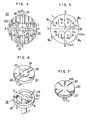
- Fig. 4 is a detailed plan view of the arc electrode of Fig. 2 or Fig. 3;
- Fig. 5 is a schematic diagram for explanation of current paths flowing through the stationary electrode assembly of Fig. 2;
- Fig. 6 is a perspective view of an arc electrode and associated coil electrode of another embodiment of the present invention; and
- Fig. 7 is a perspective view of an arc electrode of a further embodiment of the present invention.
- Referring now to Fig. 1, there is shown a vacuum interrupter 1 in accordance with an embodiment of the present invention, which includes a vacuum vessel 4 defined by a cylindrical
insulating wall 2 andmetallic end caps electrode assemblies 5 and 6,respective conductor rods 7 and 8 are extended outwardly of the vacuum vessel. A metallic bellows 9 is arranged between one of the rods 8 and therelated end cap 3B so that the movable electrode assembly 6 is separatable and contactable from and with the mated stationary one 5. Between the bothelectrode assemblies 5 and 6 and the inner wall of the insulatingcylinder 2, an intermediate metallic shield 10 is disposed. - The structures of the fixed and
movable electrode assemblies 5 and 6 will be next detailed with reference to Figs. 2 to 4. Since the both electrode assemblies 5 and 6 are the same in structure, however, the fixed one 5 alone will be explained in the following for the brevity of the explanation. - Turning first to Figs. 2 and 3, the
conductive rod 7 is formed at its one end with a hollow portion 11 which receives aspacer 13 made of high electric resistance material such as statinless steel, and astepped portion 12 which carries acoil electrode 15. Thiselectrode 15 in turn is provded withintegral arm sections 16 which extend radially outwardly from therod 7, and with a circumferential ring-shaped section 17 which is connected integrally to the arm sections. Thering section 17 is also provided with a projectedsection 18. Anarc electrode 20 is supported by theprojection 18 and thespacer 13. - The
arc electrode 20 has acontact portion 22 at the central portion thereof and amain surface portion 21 continuously connected therewith. Thecontact portion 22 extrudes toward the opposed arc electrode of the mating electrode assembly 6. Maincurrent paths 23 are formed on themain surface portion 21 as extended radially from the center 0 of thecontact portion 22 to opposed circumferential points A and B on thecoil electrode 15. A plurality ofslits 24 extends from the maincurrent paths 23 toward opposing circumferential points C and D which form right angles with respect to the points A and B, so as to define therebetween communicationcurrent paths 25 and six branchingcurrent paths 26 on thearc electrode 20. In stead of theslits 24, proper current blocking members may be provided which are made of high resistance material such as stainless steel and ceramic. The communicationcurrent paths 25 are connected at the both ends with the.projections 18 and at the central portion with thecontact portion 22, so that the current coming from thecoil electrode 15 is passed to thearc electrode 20 or the current coming from thearc electrode 20 is passed to thecoil electrode 15. The branchingcurrent paths 26 are used to branch the currents coming from the maincurrent paths 23. The main, communication and branchingcurrent paths conductive reinforcement member 27. Thereinforcement member 27 is higher in electric conductivity than themain surface portion 21 and thecontact portion 22. In other words, the electric resistance of themain surface portion 21 is greater than that of thereinforcement member 27. Conductive materials suitable for the main surface andcontact portions reinforcement 27 include Cu-Pb alloy and Cu-Bi alloy. The thickness T1 of thereinformcement 27 is greater than the thickness T2 of the main surface portion (T 1 > T 2). - The operation of the
arc electrode 20 will be next detailed with reference to Figs. 2 and 5. In thecoil electrode 15, a current I1 entering into thecoil electrode 15 from therod 7 is first divided by thearm sections 16 equally into currents of 1/2 I1 in opposite radial directions OA and OB, which divided currents of 1/2 I1 are each further divided at points A and B by thering section 17 into currents of 1/4 I1 in circumferential directions, which currents of 1/4 I1 are combined at points C and D respectively into currents of 1/2 I1 to thus flow through the communicationcurrent path 25. In this way, when the different currents in opposing directions to each other will flow through thering section 17, magnetic fluxes Φ1, Φ2, Φ3 and Φ4 are induced and the induced fluxes will cause magentic fields H1, H2' H3 and H 4 to generate in thearc electrode 20. The magnetic fields H1 to H4 are parallel to one another and cancelled out to each other at the center 0 of thearc electrode 20 with respect to the fields H1 and H3, and H2 and H4. The current Il will pass throughcontact portion 22 from the respective communicationcurrent paths 25. - As soon as the movable electrode assembly 6 is separated from the
stationary electrode assembly 5,arc 100 will take place on thecontact portion 22. When thearc 100 is subject to the parallel magnetic fields H1 to H4 and parallel magnetic fields Hi to H4 as will be explained later, thearc 100 will be dispersed into a numerous stream of arc currents I2, as shown in Fig. 4. The arc currents I2 will flow from thecontact portion 22 to theconductive reinforcement member 27 via thecurrent paths arc electrode 20 the parallel and same directioned magnetic fields H1' to H4' as in thecoil electrode 15. If these four magnetic fields Hi to H4 are equal in the strength, then the arc current I2 will pass equally through thepaths paths conductive reinforcement 27 is provided in this embodiment of the present.invention. - More specifically, the arc current 12 from the
contact portion 22 will flow through theconductive reinforcement 27. Thereinforcement 27 has an electric conductivity better than themain surface portion 21 in this embodiment such that the electric resistance of thecurrent paths main surface portion 21. This will cause the arc current I2 to flow equally through branchingpaths 26 from the maincurrent paths 23, so that a high interruption efficiency can be obtained without the generation of local heat. - When current flows through the
arc electrode 20, heat will generate, in particular, in thecontact portion 22 and the communicationcurrent paths 25. The generated heat reaches theconductive reinforcement 27 from thecontact portion 22, and further transmitted from thereinforcement 27 via thecoil electrode 15 to therod 7 for cooling. This will enable the temperature increase of thecontact portion 22 and communicationcurrent paths 25 to be reduced. Therefore, themain surface portion 21 andcontact portion 22 can pass therethrough a large current without being melted. In this connection, by providing anembossment 27A on theconductive reinforcement 27 so as to fit into thecontact portion 22 or by maintaining the relationship T1 > T2, additional cooling effect can be obtained, since the current I1 and the arc current I2 can flow promptly through theconductive reinforcement member 27. - Further, heat generated in energization of the electrode assemblies may be eliminated or cooled by applying the
reinforcement 27 onto the communicationcurrent paths 25 alone as shown in Fig. 6. - Although explanation has been made in the case where the arc electrode and coil electrode generate magnetic fields parallel to one another (parallel magnetic field electrode type) in the above embodiment, it goes without saying that heat generated in energization may be also cooled in the similar way to the above, by using such an
arc electrode 20 as shown in Fig. 7 for a coil electrode (not shown) which produces parallel magnetic fields not cancelled out to each other at the center of the electrode assembly, and by attaching theconductive reinforcement member 27 onto the back side of the arc electrode. In addition, such an arc electrode as provents any excessive current may be employed by making the arc electrode itself thinner to increase the electric resistance thereof. - As has been described above, the interruption function of the vacuum interrupter according to the present invention can be remarkably improved by employing the conductive reinforcement member having a better electric conductivity than the main surface portion of the arc electrode.
- While the present invention has been explained with reference to the preferred embodiments shown in the drawings, it should be understood that the invention is not limited to those embodiments but covers all other possible modifications, alternatives and equivalent arrangements included in the scope of the appended claims.
Claims (8)
Applications Claiming Priority (2)
| Application Number | Priority Date | Filing Date | Title |
|---|---|---|---|
| JP160715/80 | 1980-11-17 | ||
| JP55160715A JPS5784530A (en) | 1980-11-17 | 1980-11-17 | Vacuum breaker |
Publications (3)
| Publication Number | Publication Date |
|---|---|
| EP0052371A2 true EP0052371A2 (en) | 1982-05-26 |
| EP0052371A3 EP0052371A3 (en) | 1983-03-23 |
| EP0052371B1 EP0052371B1 (en) | 1985-06-05 |
Family
ID=15720897
Family Applications (1)
| Application Number | Title | Priority Date | Filing Date |
|---|---|---|---|
| EP81109720A Expired EP0052371B1 (en) | 1980-11-17 | 1981-11-16 | Vacuum interrupter |
Country Status (4)
| Country | Link |
|---|---|
| US (1) | US4427857A (en) |
| EP (1) | EP0052371B1 (en) |
| JP (1) | JPS5784530A (en) |
| DE (1) | DE3170888D1 (en) |
Cited By (8)
| Publication number | Priority date | Publication date | Assignee | Title |
|---|---|---|---|---|
| EP0104134A2 (en) * | 1982-09-21 | 1984-03-28 | Siemens Aktiengesellschaft | Vacuum switch with an annular part and diametrical arm of the contact pieces |
| EP0118844A2 (en) * | 1983-03-04 | 1984-09-19 | Hitachi, Ltd. | Vacuum switch and method of manufacturing the same |
| DE3416368A1 (en) * | 1984-04-30 | 1984-12-13 | Ernst Prof. Dr.techn.habil. 1000 Berlin Slamecka | Vacuum-switch contact arrangement |
| EP0192251A2 (en) * | 1985-02-22 | 1986-08-27 | Mitsubishi Denki Kabushiki Kaisha | Electrode of vacuum circuit breaker |
| WO1987006052A1 (en) * | 1986-03-26 | 1987-10-08 | Siemens Aktiengesellschaft Berlin Und München | Contact system for vacuum switches with an axial magnetic field |
| EP0371224A2 (en) * | 1988-11-24 | 1990-06-06 | Mitsubishi Denki Kabushiki Kaisha | Vacuum switch tube |
| EP0443236A1 (en) * | 1990-01-02 | 1991-08-28 | Cooper Industries, Inc. | Axial magnetic field vacuum interrupter |
| DE4341714A1 (en) * | 1993-12-05 | 1994-04-28 | Slamecka Ernst | Vacuum switch contact arrangement - has contacts in form of discs with chamber having internal slots and windings |
Families Citing this family (4)
| Publication number | Priority date | Publication date | Assignee | Title |
|---|---|---|---|---|
| DE3231593A1 (en) * | 1982-08-25 | 1984-03-01 | Siemens AG, 1000 Berlin und 8000 München | CONTACT ARRANGEMENT FOR VACUUM SWITCHES |
| DE3840192A1 (en) * | 1987-12-02 | 1989-06-15 | Calor Emag Elektrizitaets Ag | Switching contact arrangement |
| TW265452B (en) * | 1994-04-11 | 1995-12-11 | Hitachi Seisakusyo Kk | |
| US8319136B2 (en) * | 2010-06-29 | 2012-11-27 | Schneider Electric USA, Inc. | Arcing fault and arc flash protection system having a high-speed switch |
Citations (5)
| Publication number | Priority date | Publication date | Assignee | Title |
|---|---|---|---|---|
| US3935406A (en) * | 1973-06-30 | 1976-01-27 | Tokyo Shibaura Electric Co., Ltd. | Vacuum interrupter |
| US3946179A (en) * | 1973-09-10 | 1976-03-23 | Tokyo Shibaura Electric Co., Ltd. | Vacuum interrupter |
| US3953698A (en) * | 1973-09-28 | 1976-04-27 | Siemens Aktiengesellschaft | Contact system for a vacuum switch |
| US4196327A (en) * | 1976-12-06 | 1980-04-01 | Hitachi, Ltd. | Vacuum interrupter |
| GB2038557A (en) * | 1978-11-22 | 1980-07-23 | Hitachi Ltd | Vacuum interrupter |
-
1980
- 1980-11-17 JP JP55160715A patent/JPS5784530A/en active Pending
-
1981
- 1981-11-10 US US06/319,985 patent/US4427857A/en not_active Expired - Fee Related
- 1981-11-16 EP EP81109720A patent/EP0052371B1/en not_active Expired
- 1981-11-16 DE DE8181109720T patent/DE3170888D1/en not_active Expired
Patent Citations (5)
| Publication number | Priority date | Publication date | Assignee | Title |
|---|---|---|---|---|
| US3935406A (en) * | 1973-06-30 | 1976-01-27 | Tokyo Shibaura Electric Co., Ltd. | Vacuum interrupter |
| US3946179A (en) * | 1973-09-10 | 1976-03-23 | Tokyo Shibaura Electric Co., Ltd. | Vacuum interrupter |
| US3953698A (en) * | 1973-09-28 | 1976-04-27 | Siemens Aktiengesellschaft | Contact system for a vacuum switch |
| US4196327A (en) * | 1976-12-06 | 1980-04-01 | Hitachi, Ltd. | Vacuum interrupter |
| GB2038557A (en) * | 1978-11-22 | 1980-07-23 | Hitachi Ltd | Vacuum interrupter |
Cited By (13)
| Publication number | Priority date | Publication date | Assignee | Title |
|---|---|---|---|---|
| EP0104134A3 (en) * | 1982-09-21 | 1986-10-22 | Siemens Aktiengesellschaft | Vacuum switch with an annular part and diametrical arm of the contact pieces |
| EP0104134A2 (en) * | 1982-09-21 | 1984-03-28 | Siemens Aktiengesellschaft | Vacuum switch with an annular part and diametrical arm of the contact pieces |
| EP0118844A2 (en) * | 1983-03-04 | 1984-09-19 | Hitachi, Ltd. | Vacuum switch and method of manufacturing the same |
| EP0118844A3 (en) * | 1983-03-04 | 1985-01-09 | Hitachi, Ltd. | Vacuum switch and method of manufacturing the same |
| DE3416368A1 (en) * | 1984-04-30 | 1984-12-13 | Ernst Prof. Dr.techn.habil. 1000 Berlin Slamecka | Vacuum-switch contact arrangement |
| EP0192251A3 (en) * | 1985-02-22 | 1989-02-22 | Mitsubishi Denki Kabushiki Kaisha | Electrode of vacuum circuit breaker |
| EP0192251A2 (en) * | 1985-02-22 | 1986-08-27 | Mitsubishi Denki Kabushiki Kaisha | Electrode of vacuum circuit breaker |
| WO1987006052A1 (en) * | 1986-03-26 | 1987-10-08 | Siemens Aktiengesellschaft Berlin Und München | Contact system for vacuum switches with an axial magnetic field |
| US4935588A (en) * | 1986-03-26 | 1990-06-19 | Siemens Aktiengesellschaft | Contact arrangement for vacuum switches with axial magnetic fields |
| EP0371224A2 (en) * | 1988-11-24 | 1990-06-06 | Mitsubishi Denki Kabushiki Kaisha | Vacuum switch tube |
| EP0371224A3 (en) * | 1988-11-24 | 1990-10-03 | Mitsubishi Denki Kabushiki Kaisha | Vacuum switch tube |
| EP0443236A1 (en) * | 1990-01-02 | 1991-08-28 | Cooper Industries, Inc. | Axial magnetic field vacuum interrupter |
| DE4341714A1 (en) * | 1993-12-05 | 1994-04-28 | Slamecka Ernst | Vacuum switch contact arrangement - has contacts in form of discs with chamber having internal slots and windings |
Also Published As
| Publication number | Publication date |
|---|---|
| US4427857A (en) | 1984-01-24 |
| EP0052371A3 (en) | 1983-03-23 |
| JPS5784530A (en) | 1982-05-26 |
| EP0052371B1 (en) | 1985-06-05 |
| DE3170888D1 (en) | 1985-07-11 |
Similar Documents
| Publication | Publication Date | Title |
|---|---|---|
| US4704506A (en) | Vacuum interrupter | |
| US3280286A (en) | Vacuum-type circuit interrupter | |
| US3469050A (en) | Arc rotating coil structure in vacuum circuit interrupters | |
| EP0329410B1 (en) | Vacuum interrupter | |
| CA1224233A (en) | Vacuum interrupter | |
| US4427857A (en) | Vacuum interrupter | |
| EP0597434B1 (en) | Vacuum interrupter | |
| JPS58111231A (en) | Vacuum valve for breaker | |
| JP3159827B2 (en) | Vacuum circuit breaker, electrode for vacuum circuit breaker and method of manufacturing the same | |
| KR920006060B1 (en) | Vacuum switch tube | |
| JPS6171520A (en) | Contactor unit of vacuum switching implement | |
| US4695689A (en) | Vacuum circuit breaker | |
| KR880002576B1 (en) | Vaccum breaker | |
| US3591743A (en) | Vacuum-type circuit interrupter with flexible, weld-breaking contact structure | |
| US4855547A (en) | Vacuum interrupter | |
| JPS63304543A (en) | Vacuum breaker | |
| JP2001006501A (en) | Vacuum valve | |
| KR910006238B1 (en) | Vacuum intakaputa | |
| JPH10321092A (en) | Bias electrode for vacuum valve and vacuum valve using the bias electrode and vacuum circuit breaker using the vacuum valve | |
| JPS639968Y2 (en) | ||
| US4760222A (en) | Vacuum circuit interrupter | |
| JPS6318292B2 (en) | ||
| JP3219483B2 (en) | Vacuum valve | |
| JP3243162B2 (en) | Vacuum valve | |
| JPS6310855B2 (en) |
Legal Events
| Date | Code | Title | Description |
|---|---|---|---|
| PUAI | Public reference made under article 153(3) epc to a published international application that has entered the european phase |
Free format text: ORIGINAL CODE: 0009012 |
|
| AK | Designated contracting states |
Designated state(s): CH DE FR GB SE |
|
| PUAL | Search report despatched |
Free format text: ORIGINAL CODE: 0009013 |
|
| AK | Designated contracting states |
Designated state(s): CH DE FR GB LI SE |
|
| 17P | Request for examination filed |
Effective date: 19830208 |
|
| GRAA | (expected) grant |
Free format text: ORIGINAL CODE: 0009210 |
|
| AK | Designated contracting states |
Designated state(s): CH DE FR GB LI SE |
|
| REF | Corresponds to: |
Ref document number: 3170888 Country of ref document: DE Date of ref document: 19850711 |
|
| ET | Fr: translation filed | ||
| PLBE | No opposition filed within time limit |
Free format text: ORIGINAL CODE: 0009261 |
|
| STAA | Information on the status of an ep patent application or granted ep patent |
Free format text: STATUS: NO OPPOSITION FILED WITHIN TIME LIMIT |
|
| 26N | No opposition filed | ||
| PGFP | Annual fee paid to national office [announced via postgrant information from national office to epo] |
Ref country code: CH Payment date: 19920129 Year of fee payment: 11 |
|
| PGFP | Annual fee paid to national office [announced via postgrant information from national office to epo] |
Ref country code: FR Payment date: 19920918 Year of fee payment: 12 |
|
| PGFP | Annual fee paid to national office [announced via postgrant information from national office to epo] |
Ref country code: GB Payment date: 19920923 Year of fee payment: 12 |
|
| PGFP | Annual fee paid to national office [announced via postgrant information from national office to epo] |
Ref country code: SE Payment date: 19921005 Year of fee payment: 12 |
|
| PG25 | Lapsed in a contracting state [announced via postgrant information from national office to epo] |
Ref country code: SE Effective date: 19921117 |
|
| PG25 | Lapsed in a contracting state [announced via postgrant information from national office to epo] |
Ref country code: LI Effective date: 19921130 Ref country code: CH Effective date: 19921130 |
|
| PGFP | Annual fee paid to national office [announced via postgrant information from national office to epo] |
Ref country code: DE Payment date: 19921231 Year of fee payment: 12 |
|
| REG | Reference to a national code |
Ref country code: CH Ref legal event code: PL |
|
| PG25 | Lapsed in a contracting state [announced via postgrant information from national office to epo] |
Ref country code: GB Effective date: 19931116 |
|
| GBPC | Gb: european patent ceased through non-payment of renewal fee |
Effective date: 19931116 |
|
| PG25 | Lapsed in a contracting state [announced via postgrant information from national office to epo] |
Ref country code: FR Effective date: 19940729 |
|
| PG25 | Lapsed in a contracting state [announced via postgrant information from national office to epo] |
Ref country code: DE Effective date: 19940802 |
|
| REG | Reference to a national code |
Ref country code: FR Ref legal event code: ST |
|
| EUG | Se: european patent has lapsed |
Ref document number: 81109720.3 Effective date: 19930610 |