EP0052039A1 - Kühlkasten für Hochöfen - Google Patents
Kühlkasten für Hochöfen Download PDFInfo
- Publication number
- EP0052039A1 EP0052039A1 EP81401681A EP81401681A EP0052039A1 EP 0052039 A1 EP0052039 A1 EP 0052039A1 EP 81401681 A EP81401681 A EP 81401681A EP 81401681 A EP81401681 A EP 81401681A EP 0052039 A1 EP0052039 A1 EP 0052039A1
- Authority
- EP
- European Patent Office
- Prior art keywords
- plate according
- cooling
- cast iron
- face
- tubes
- Prior art date
- Legal status (The legal status is an assumption and is not a legal conclusion. Google has not performed a legal analysis and makes no representation as to the accuracy of the status listed.)
- Granted
Links
Images

Classifications
-
- C—CHEMISTRY; METALLURGY
- C21—METALLURGY OF IRON
- C21B—MANUFACTURE OF IRON OR STEEL
- C21B7/00—Blast furnaces
- C21B7/10—Cooling; Devices therefor
Definitions
- the present invention relates to cooling plates for blast furnaces.
- These cooling plates are elements placed against the internal face of the shielding and fulfill the dual function of vigorous cooling of the refractory and of screen as the heat flow passes through the shielding.
- the cooling plates consist of cast iron elements traversed in their mass by a network of tubes in which circulates a cooling fluid which is generally water. These cooling tubes open at the top and bottom parts respectively of the cooling plates and pass through the shield, outside of which they are connected to cooling tubes of an adjacent upper or lower plate.
- the tubes thus connected determine the circulation lines of the fluid rising in a substantially vertical plane along the wall of the blast furnace, these lines being connected to an external circuit for circulation and cooling of the fluid.
- the cooling plates must be designed in such a way that they resist thermomechanical deformation resulting from the high fluxes generated in the blast furnace and, in addition, so as to ensure a good heat exchange with the refractory and to ensure the effective attachment of this last.
- the cooling plates known so far do not fully satisfy these conditions and have defects which lead, following repeated thermal stresses, to. the formation of cracks in their mass e.t, by way of. as a consequence, the release of water into the blast furnace, in the form of leaks of the cooling fluid, as well as poor mechanical strength of the cooling tubes at their exit from the cooling plates and through the shielding. There is, moreover, a difficulty in fixing the refractory lining permanently on the cooling plates.
- the object of the present invention is to remedy these drawbacks by providing cooling plates with increased operating safety, having better characteristics of heat exchange and attachment of the refractory lining.
- the present invention thus relates to a cooling plate consisting of a cast iron element of substantially parallelepiped shape, in which are embedded longitudinal tubes arranged parallel to each other, these tubes opening onto the same main face, respectively to the upper parts and bottom of the cooling plate in a protective sheath, characterized in that the face opposite to that where the cooling tubes open out is embossed.
- the transverse grooves of the embossed face include silicon carbide inserts.
- the embossed face has a projecting part called a coping.
- This coping is arranged at the upper part or at a middle part of the embossed face, or can constitute the upper edge of the cooling plate.
- the cooling plate 1 arranged vertically, is placed between the shield 2 of the blast furnace and the refractory lining 3.
- the cooling plate 1 rests against the internal wall of the shield by bosses 4 projecting from the main face 5 hovers opposite the shielding.
- the cooling plate is traversed by longitudinal tubes 6 for circulation of the cooling fluid arranged parallel to each other and extending along a longitudinal axis disposed vertically.
- the tubes 6 open from the plate 1 to the upper and lower parts, respectively, in sleeves 7 and 8 which are embedded in the mass of cast iron of the cooling plate.
- the part of the cooling tubes leaving the plates and their sheaths are arranged in such a way that they are strictly horizontal, that is to say that they are slightly inclined relative to the perpendicular to the surface of the shield at the point of crossing of the latter.
- the face 9 of the cooling plate opposite to the face 5, which is the face on which the cooling tubes open, has an embossed shape.
- This embossed shape is obtained by the intersection at right angles to longitudinal 10 and transverse grooves 11, the longitudinal grooves 10 being parallel to the tubes 6.
- the grooves can have a square, rectangular or trapezoidal cross section.
- the longitudinal grooves 10 have a trapezoidal section whose flared part is directed towards the outside of the plate, while the transverse grooves 11 have a trapezoidal section arranged in dovetail.
- inserts 12 of corresponding trapezoidal section which project from the embossed face 9 of the cooling plate.
- inserts are made of silicon carbide and placed in situ during the casting of the cast iron from the cooling plate. This characteristic of casting the cast iron around the bricks of special silicon carbide, allows an intimate contact, ensured by a chemical bond, between the silicon carbide and the cast iron, which guarantees an excellent coefficient of heat transfer between the two materials.
- transverse grooves On the cooling plate shown in fig. 1, all the transverse grooves have inserts made of silicon carbide, but it is possible to space these inserts every two or three grooves and even to have none.
- the transverse grooves without an insert can have a trapezoidal cross section whose flared part is directed towards the outside of the plate.
- the embossing of the face 9 opposite the refractory lining makes it possible, first of all, to increase the interface between the refractory lining and the cast iron and, therefore, to promote heat exchange. It also performs a mechanical anchoring function of the refractory inside the blast furnace.
- the silicon carbide inserts play a role in improving the bond between the cast iron and the refractory lining. Furthermore, in the event of a disappearance of the refractory lining during operation blast furnace, these elements promote self-filling and provide abrasion resistance.
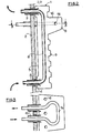
- fig. 2 is shown in section a cooling plate of the coping type.
- the cooling plate as in the general case of fig. 1, is placed against the internal face of the shield 2.
- Longitudinal cooling tubes 6 are embedded in the cast iron mass of the cooling plate and exit at the top and bottom in protective sleeves 7 and 8 which pass through the shield 2.
- stuffing masses intended to ensure a solution of continuity of the refractory lining system, cooling plate and shielding are arranged between the face 5 of the cooling plate and the shield.
- the cooling plate is held in close contact against the shielding by means external to the latter, not shown.
- a coping 13 projecting from the embossed face 9 of the cooling plate comprises, embedded in its mass, a transverse tube 14 for circulation of the cooling fluid, which opens on the face 5 opposite the shielding, through protective sleeves 15 , embedded in the metallic mass of the cooling plate and passing through the shield 2.
- the transverse tube is arranged in such a way that it passes between the longitudinal tubes 6 for circulation of the cooling fluid.
- the transverse tubes 14 are connected outside the blast furnace to other similar tubes cooling copings of other upper or lower cooling plates.
- the circuit of the transverse cooling tubes is likewise connected to an external circuit for circulation and cooling of the fluid.
- the coping may include a cooling tube, as shown in figs. 2 and 3, but you can also have several, depending on the size of the coping.
- This coping can be arranged at a part slightly lower at the upper edge of the cooling plate, or at a more median part, or constitute the upper edge of the cooling plate.
- the copings are arranged at a lower part at the upper edge of the cooling surface or more median, whereas for the last row located in the tank area, the coping forms the upper edge of the cooling plates.
- the coping may also have CSi inserts in grooves made for this purpose.
- the copings 13 have an upper face 16 substantially perpendicular to the embossed face 9 so that it is substantially horizontal when the cooling plate is positioned in the blast furnace.
- the cooling plates include a number of longitudinal cooling tubes 6 which can vary from 3 to 5.
- the density of the internal cooling tubes is varied as a function of the heat fluxes emitted in the blast furnace and it is obvious that the more this heat flow is intense, the more the distance between the tubes must be reduced.
- the cooling plates at the belly there are tubes at a center distance of 195 to 210 mm, while in the less stressed areas of the tank, this center distance is increased to 270-320 mm.
- the dimensions of the plates are also a function of the heat flux emitted in the various areas at the top furnace.
- there are cooling plates of smaller dimensions comprising the same number of tubes as in the zones stressed by a less intense heat flow.
- the cooling plates are made of cast iron which must have, in addition to the qualities inherent in this material, characteristics specific to its particular use.
- Fonts of types (a) and (b) present the following analysis in percentage by weight.
- Fonts of types (a) and (b) differ only in their crystallographic structure.
- Cast iron of type (b) is of controlled lamellar graphite of rounded type A predominant, stabilized and of high conductivity. This particular crystallographic structure is obtained by a selected oven, a control of overheating and by inoculation.
- Cast iron of type (c) with aluminum presents the following analysis in percentage by weight: Inoculation agent based on Cr alloy, expressed in Cr: 0.3 to 2%.
- an inoculating agent an alloy based on copper and rare earths, the proportion of cerium in the rare earths is 50%, the proportion of Cu and rare earths in the alloy being identical to that defined. for Cr.
- This aluminum cast iron does not quench, it retains at high temperature its conductivity and its mechanical resistance to abrasion and cracking.
- Type C cast iron is used in the most stressed places of the blast furnace, by heat fluxes, and by mechanical abrasion effects, in particular for the cooling plates of the bottom of the tank, with curbs, and of the belly.
- the cast iron has the following composition in percentage by weight:
Landscapes
- Engineering & Computer Science (AREA)
- Chemical & Material Sciences (AREA)
- Manufacturing & Machinery (AREA)
- Materials Engineering (AREA)
- Metallurgy (AREA)
- Organic Chemistry (AREA)
- Blast Furnaces (AREA)
- Furnace Housings, Linings, Walls, And Ceilings (AREA)
- Waste-Gas Treatment And Other Accessory Devices For Furnaces (AREA)
- Magnetic Resonance Imaging Apparatus (AREA)
Priority Applications (1)
| Application Number | Priority Date | Filing Date | Title |
|---|---|---|---|
| AT81401681T ATE11570T1 (de) | 1980-11-07 | 1981-10-23 | Kuehlkasten fuer hochoefen. |
Applications Claiming Priority (2)
| Application Number | Priority Date | Filing Date | Title |
|---|---|---|---|
| FR8023805 | 1980-11-07 | ||
| FR8023805A FR2493871A1 (fr) | 1980-11-07 | 1980-11-07 | Plaques de refroidissement pour hauts fourneaux |
Publications (2)
| Publication Number | Publication Date |
|---|---|
| EP0052039A1 true EP0052039A1 (de) | 1982-05-19 |
| EP0052039B1 EP0052039B1 (de) | 1985-01-30 |
Family
ID=9247776
Family Applications (1)
| Application Number | Title | Priority Date | Filing Date |
|---|---|---|---|
| EP81401681A Expired EP0052039B1 (de) | 1980-11-07 | 1981-10-23 | Kühlkasten für Hochöfen |
Country Status (7)
| Country | Link |
|---|---|
| US (1) | US4437651A (de) |
| EP (1) | EP0052039B1 (de) |
| JP (1) | JPS57110606A (de) |
| AT (1) | ATE11570T1 (de) |
| CA (1) | CA1154590A (de) |
| DE (1) | DE3168672D1 (de) |
| FR (1) | FR2493871A1 (de) |
Cited By (10)
| Publication number | Priority date | Publication date | Assignee | Title |
|---|---|---|---|---|
| FR2552105A1 (fr) * | 1983-09-21 | 1985-03-22 | Usinor | Perfectionnement aux plaques de refroidissement pour hauts-fourneaux |
| FR2698105A1 (fr) * | 1992-11-13 | 1994-05-20 | Mtu Muenchen Gmbh | Pièce en un substrat de base métallique comportant un revêtement céramique. |
| EP1074806A1 (de) * | 1999-08-06 | 2001-02-07 | KM Europa Metal Aktiengesellschaft | Kühlelement |
| US7537724B2 (en) | 2002-08-20 | 2009-05-26 | Siemens Vai Metals Technologies Gmbh & Co. | Cooling plate for metallurgic furnaces |
| AU2005210677B2 (en) * | 2004-02-04 | 2009-12-10 | Tata Steel Limited | Metallurgical vessel |
| LU91551B1 (en) * | 2009-04-14 | 2010-10-15 | Wurth Paul Sa | Cooling plate for a metallurgical furnace |
| US8038932B2 (en) | 2004-02-04 | 2011-10-18 | Technological Resources Pty. Limited | Metallurgical vessel |
| LU91788B1 (en) * | 2011-02-08 | 2012-08-09 | Wurth Paul Sa | Stave cooler for a metallurgical furnace |
| US8545752B2 (en) | 2008-06-06 | 2013-10-01 | Paul Wurth S.A. | Cooling plate for a metallurgical furnace |
| WO2018122590A1 (en) * | 2016-12-30 | 2018-07-05 | Arcelormittal | Copper cooling plate with wear resistant inserts, for a blast furnace |
Families Citing this family (22)
| Publication number | Priority date | Publication date | Assignee | Title |
|---|---|---|---|---|
| DE3323781C2 (de) * | 1983-07-01 | 1986-04-03 | Uhde Gmbh, 4600 Dortmund | Einrichtung zur Kühlung dickwandiger, waagerecht angeordneter Rohrböden von Wärmetauschern |
| JPH0193841U (de) * | 1987-12-15 | 1989-06-20 | ||
| DE3925280A1 (de) * | 1989-07-31 | 1991-02-07 | Gutehoffnungshuette Man | Fluessigkeitsdurchstroemtes kuehlelement fuer schachtoefen |
| US5464592A (en) * | 1993-11-22 | 1995-11-07 | Texaco Inc. | Gasifier throat |
| DE19503912C2 (de) * | 1995-02-07 | 1997-02-06 | Gutehoffnungshuette Man | Kühlplatte für Schachtöfen, insbesondere Hochöfen |
| KR100367467B1 (ko) * | 1999-02-03 | 2003-01-10 | 신닛뽄세이테쯔 카부시키카이샤 | 아크로의 노벽 및 노덮개용 수냉패널 |
| NL1011838C2 (nl) * | 1999-04-20 | 2000-10-23 | Hoogovens Technical Services B | Koelpaneel voor een schachtoven, schachtoven voorzien van dergelijke koelpanelen en een werkwijze voor de vervaardiging van zo'n koelpaneel. |
| US6676597B2 (en) * | 2001-01-13 | 2004-01-13 | Medtronic, Inc. | Method and device for organ positioning |
| KR100815808B1 (ko) * | 2001-12-26 | 2008-03-20 | 주식회사 포스코 | 용광로의 이중구조 스테이브 냉각장치 |
| CN100343395C (zh) * | 2002-03-12 | 2007-10-17 | Km欧洲钢铁股份有限公司 | 冷却元件 |
| FI115251B (fi) * | 2002-07-31 | 2005-03-31 | Outokumpu Oy | Jäähdytyselementti |
| DE10249333B4 (de) * | 2002-10-22 | 2005-09-08 | Refractory Intellectual Property Gmbh & Co. Kg | Metallurgisches Schmelzgefäß |
| US6870873B2 (en) * | 2003-05-28 | 2005-03-22 | Systems Spray-Cooled, Inc. | Device for improved slag retention in water cooled furnace elements |
| FI116317B (fi) * | 2003-06-12 | 2005-10-31 | Outokumpu Oy | Jäähdytyselementti ja menetelmä jäähdytyselementin valmistamiseksi |
| US7832367B2 (en) * | 2007-12-05 | 2010-11-16 | Berry Metal Company | Furnace panel leak detection system |
| BR112012020858A2 (pt) * | 2010-02-23 | 2016-08-23 | Nippon Steel Corp | aduela e alto-forno. |
| EP2553372A1 (de) * | 2010-03-30 | 2013-02-06 | Berry Metal Company | Vorrichtung und verfahren für die stütze eines gasdichten sekundären plattenkühlers |
| US8834784B2 (en) * | 2011-01-27 | 2014-09-16 | Allan J. MacRae | Thin stave cooler and support frame system |
| RU2718027C2 (ru) * | 2016-02-18 | 2020-03-30 | Хэтч Лтд. | Износостойкий композитный материал, его применение в охлаждающих элементах для металлургической печи и способ его получения |
| DE102016107284A1 (de) * | 2016-04-20 | 2017-10-26 | Kme Germany Gmbh & Co. Kg | Kühlplatte für ein Kühlelement für metallurgische Öfen |
| CA3045969C (en) * | 2016-12-30 | 2021-07-27 | Arcelormittal | Copper cooling plate with multilayer protrusions comprising wear resistant material, for a blast furnace |
| RU2682499C1 (ru) * | 2017-09-21 | 2019-03-19 | Общество с ограниченной ответственностью "Севен Рефракториз" | Способ футеровки шахты доменной печи, холодильный блок шахты доменной печи и способ его изготовления |
Citations (9)
| Publication number | Priority date | Publication date | Assignee | Title |
|---|---|---|---|---|
| DE1533864A1 (de) * | 1967-03-08 | 1970-03-19 | Rohde Dr Ing Ewald W | Kuehlkaesten fuer Hochoefen |
| DE1508059A1 (de) * | 1966-07-08 | 1970-07-23 | Rohde Dr Ing Ewald W | Hochofen-Kuehlkasten fuer Kaltwasser- oder Verdampfungskuehlung |
| FR2203966A1 (de) * | 1972-10-19 | 1974-05-17 | Didier Werke Ag | |
| FR2230730A1 (de) * | 1973-05-25 | 1974-12-20 | Inst Ochistke T | |
| FR2257068A1 (en) * | 1974-01-03 | 1975-08-01 | Hoogovens Ijmuiden Bv | Cooling panels for blast furnaces - providing cooling for internal refractory lining support ribs |
| US3940552A (en) * | 1974-01-23 | 1976-02-24 | Daido Seiko Kabushiki Kaisha | Water-cooled panel for arc furnace |
| FR2371652A2 (fr) * | 1976-11-23 | 1978-06-16 | Sofresid | Plaque de refroidissement pour parois de fours a cuve, notamment pour hauts-fourneaux |
| US4161620A (en) * | 1976-11-17 | 1979-07-17 | Kyoei Seiko Kabushiki Kaisha | Electric arc furnace for steel making, with no refractory bricks at the furnace wall |
| EP0012132A1 (de) * | 1978-12-01 | 1980-06-11 | Arbed S.A. | Metallische Kühlelemente für Industrieöfen |
-
1980
- 1980-11-07 FR FR8023805A patent/FR2493871A1/fr active Granted
-
1981
- 1981-10-23 DE DE8181401681T patent/DE3168672D1/de not_active Expired
- 1981-10-23 EP EP81401681A patent/EP0052039B1/de not_active Expired
- 1981-10-23 AT AT81401681T patent/ATE11570T1/de not_active IP Right Cessation
- 1981-11-06 CA CA000389589A patent/CA1154590A/en not_active Expired
- 1981-11-07 JP JP56178919A patent/JPS57110606A/ja active Granted
- 1981-11-09 US US06/319,281 patent/US4437651A/en not_active Expired - Lifetime
Patent Citations (9)
| Publication number | Priority date | Publication date | Assignee | Title |
|---|---|---|---|---|
| DE1508059A1 (de) * | 1966-07-08 | 1970-07-23 | Rohde Dr Ing Ewald W | Hochofen-Kuehlkasten fuer Kaltwasser- oder Verdampfungskuehlung |
| DE1533864A1 (de) * | 1967-03-08 | 1970-03-19 | Rohde Dr Ing Ewald W | Kuehlkaesten fuer Hochoefen |
| FR2203966A1 (de) * | 1972-10-19 | 1974-05-17 | Didier Werke Ag | |
| FR2230730A1 (de) * | 1973-05-25 | 1974-12-20 | Inst Ochistke T | |
| FR2257068A1 (en) * | 1974-01-03 | 1975-08-01 | Hoogovens Ijmuiden Bv | Cooling panels for blast furnaces - providing cooling for internal refractory lining support ribs |
| US3940552A (en) * | 1974-01-23 | 1976-02-24 | Daido Seiko Kabushiki Kaisha | Water-cooled panel for arc furnace |
| US4161620A (en) * | 1976-11-17 | 1979-07-17 | Kyoei Seiko Kabushiki Kaisha | Electric arc furnace for steel making, with no refractory bricks at the furnace wall |
| FR2371652A2 (fr) * | 1976-11-23 | 1978-06-16 | Sofresid | Plaque de refroidissement pour parois de fours a cuve, notamment pour hauts-fourneaux |
| EP0012132A1 (de) * | 1978-12-01 | 1980-06-11 | Arbed S.A. | Metallische Kühlelemente für Industrieöfen |
Cited By (18)
| Publication number | Priority date | Publication date | Assignee | Title |
|---|---|---|---|---|
| FR2552105A1 (fr) * | 1983-09-21 | 1985-03-22 | Usinor | Perfectionnement aux plaques de refroidissement pour hauts-fourneaux |
| EP0142399A1 (de) * | 1983-09-21 | 1985-05-22 | Sollac | Plattenkühler für Hochöfen |
| FR2698105A1 (fr) * | 1992-11-13 | 1994-05-20 | Mtu Muenchen Gmbh | Pièce en un substrat de base métallique comportant un revêtement céramique. |
| EP1074806A1 (de) * | 1999-08-06 | 2001-02-07 | KM Europa Metal Aktiengesellschaft | Kühlelement |
| US7537724B2 (en) | 2002-08-20 | 2009-05-26 | Siemens Vai Metals Technologies Gmbh & Co. | Cooling plate for metallurgic furnaces |
| US8038932B2 (en) | 2004-02-04 | 2011-10-18 | Technological Resources Pty. Limited | Metallurgical vessel |
| AU2005210677B2 (en) * | 2004-02-04 | 2009-12-10 | Tata Steel Limited | Metallurgical vessel |
| US8545752B2 (en) | 2008-06-06 | 2013-10-01 | Paul Wurth S.A. | Cooling plate for a metallurgical furnace |
| LU91551B1 (en) * | 2009-04-14 | 2010-10-15 | Wurth Paul Sa | Cooling plate for a metallurgical furnace |
| WO2010119013A1 (en) * | 2009-04-14 | 2010-10-21 | Paul Wurth S.A. | Cooling plate for a metallurgical furnace |
| EA020449B1 (ru) * | 2009-04-14 | 2014-11-28 | Поль Вурт С.А. | Холодильная плита для металлургической печи |
| US8920709B2 (en) | 2009-04-14 | 2014-12-30 | Paul Wurth S.A. | Cooling plate for a metallurgical furnace |
| LU91788B1 (en) * | 2011-02-08 | 2012-08-09 | Wurth Paul Sa | Stave cooler for a metallurgical furnace |
| WO2012107322A1 (en) | 2011-02-08 | 2012-08-16 | Paul Wurth S.A. | Stave cooler for a metallurgical furnace |
| CN103348018A (zh) * | 2011-02-08 | 2013-10-09 | 保尔伍斯股份有限公司 | 用于冶金炉的板式冷却器 |
| WO2018122590A1 (en) * | 2016-12-30 | 2018-07-05 | Arcelormittal | Copper cooling plate with wear resistant inserts, for a blast furnace |
| RU2718775C1 (ru) * | 2016-12-30 | 2020-04-14 | Арселормиттал | Медная холодильная плита с износостойкими вставками для доменной печи |
| US11150020B2 (en) | 2016-12-30 | 2021-10-19 | Arcelormittal | Copper cooling plate with wear resistant inserts, for a blast furnace |
Also Published As
| Publication number | Publication date |
|---|---|
| FR2493871A1 (fr) | 1982-05-14 |
| EP0052039B1 (de) | 1985-01-30 |
| DE3168672D1 (en) | 1985-03-14 |
| US4437651A (en) | 1984-03-20 |
| ATE11570T1 (de) | 1985-02-15 |
| JPS57110606A (en) | 1982-07-09 |
| FR2493871B1 (de) | 1982-12-10 |
| JPS621441B2 (de) | 1987-01-13 |
| CA1154590A (en) | 1983-10-04 |
Similar Documents
| Publication | Publication Date | Title |
|---|---|---|
| EP0052039B1 (de) | Kühlkasten für Hochöfen | |
| US4097679A (en) | Side wall of the ultra high power electric arc furnaces for steelmaking | |
| LU83985A1 (fr) | Plaque de refroidissement | |
| EP3728974B1 (de) | Ofen mit eingetauchtem brenner mit selbsttiegelwand | |
| NO126613B (de) | ||
| EP0090761A1 (de) | Rinne für eine Metallschmelze | |
| EP0239442B1 (de) | Befestigungen von Schutzelementen in Heizkesselbrennkammern | |
| JP2000119713A (ja) | ステーブ | |
| EP0142399B1 (de) | Plattenkühler für Hochöfen | |
| LU80606A1 (fr) | Elements de refroidissement metalliques pour fours industriels | |
| EP0062573B1 (de) | Erhitzer für festen Brennstoff | |
| FR2570942A1 (fr) | Friteuse a multiconvection d'huile et a bruleurs a gaz | |
| FR2533680A1 (fr) | Refroidisseur pour les fours verticaux | |
| EP0239438A1 (de) | Befestigungen von Schutzelementen in Heizkesselbrennkammern | |
| US1535160A (en) | Rabble furnace | |
| FR3075943A1 (fr) | Four a bruleur immerge a paroi auto-creuset | |
| LU82781A1 (fr) | Dispositif recuperateur de calories a circulation d'eau pour cheminees | |
| FR2558173A1 (fr) | Enveloppe de cowper et son procede de fabrication | |
| EP0907693A1 (de) | Einrichtung zum dampfkracken mit schutzmitteln gegen erosion | |
| FR2523283A1 (fr) | Dispositif de refroidissement des parois d'un four notamment d'un four metallurgique a cuve | |
| FR2523276A1 (fr) | Element de construction pour l'etablissement d'une installation de chauffage et installation de chauffage obtenue | |
| EP0350356A1 (de) | Ofenoberschwelle | |
| FR2526928A1 (fr) | Dispositif de refroidissement de la paroi d'un four metallurgique | |
| BE368476A (de) | ||
| FR2493473A1 (fr) | Chaudiere pouvant utiliser des combustibles varies |
Legal Events
| Date | Code | Title | Description |
|---|---|---|---|
| PUAI | Public reference made under article 153(3) epc to a published international application that has entered the european phase |
Free format text: ORIGINAL CODE: 0009012 |
|
| 17P | Request for examination filed |
Effective date: 19820305 |
|
| AK | Designated contracting states |
Designated state(s): AT BE CH DE GB IT LI LU NL SE |
|
| RAP1 | Party data changed (applicant data changed or rights of an application transferred) |
Owner name: UNION SIDERURGIQUE DU NORD ET DE L'EST DE LA FRANC |
|
| ITF | It: translation for a ep patent filed |
Owner name: BARZANO' E ZANARDO MILANO S.P.A. |
|
| GRAA | (expected) grant |
Free format text: ORIGINAL CODE: 0009210 |
|
| AK | Designated contracting states |
Designated state(s): AT BE CH DE GB IT LI LU NL SE |
|
| REF | Corresponds to: |
Ref document number: 11570 Country of ref document: AT Date of ref document: 19850215 Kind code of ref document: T |
|
| REF | Corresponds to: |
Ref document number: 3168672 Country of ref document: DE Date of ref document: 19850314 |
|
| PLBE | No opposition filed within time limit |
Free format text: ORIGINAL CODE: 0009261 |
|
| STAA | Information on the status of an ep patent application or granted ep patent |
Free format text: STATUS: NO OPPOSITION FILED WITHIN TIME LIMIT |
|
| 26N | No opposition filed | ||
| ITTA | It: last paid annual fee | ||
| EPTA | Lu: last paid annual fee | ||
| PGFP | Annual fee paid to national office [announced via postgrant information from national office to epo] |
Ref country code: CH Payment date: 19940916 Year of fee payment: 14 |
|
| EAL | Se: european patent in force in sweden |
Ref document number: 81401681.2 |
|
| PG25 | Lapsed in a contracting state [announced via postgrant information from national office to epo] |
Ref country code: LI Effective date: 19951031 Ref country code: CH Effective date: 19951031 |
|
| REG | Reference to a national code |
Ref country code: CH Ref legal event code: PL |
|
| PGFP | Annual fee paid to national office [announced via postgrant information from national office to epo] |
Ref country code: LU Payment date: 19960901 Year of fee payment: 16 |
|
| PGFP | Annual fee paid to national office [announced via postgrant information from national office to epo] |
Ref country code: DE Payment date: 19960923 Year of fee payment: 16 |
|
| PGFP | Annual fee paid to national office [announced via postgrant information from national office to epo] |
Ref country code: NL Payment date: 19960926 Year of fee payment: 16 |
|
| PGFP | Annual fee paid to national office [announced via postgrant information from national office to epo] |
Ref country code: AT Payment date: 19961002 Year of fee payment: 16 |
|
| PGFP | Annual fee paid to national office [announced via postgrant information from national office to epo] |
Ref country code: GB Payment date: 19961015 Year of fee payment: 16 |
|
| PGFP | Annual fee paid to national office [announced via postgrant information from national office to epo] |
Ref country code: SE Payment date: 19961017 Year of fee payment: 16 |
|
| PGFP | Annual fee paid to national office [announced via postgrant information from national office to epo] |
Ref country code: BE Payment date: 19961118 Year of fee payment: 16 |
|
| PG25 | Lapsed in a contracting state [announced via postgrant information from national office to epo] |
Ref country code: LU Free format text: LAPSE BECAUSE OF NON-PAYMENT OF DUE FEES Effective date: 19971023 Ref country code: GB Free format text: LAPSE BECAUSE OF NON-PAYMENT OF DUE FEES Effective date: 19971023 Ref country code: AT Free format text: LAPSE BECAUSE OF NON-PAYMENT OF DUE FEES Effective date: 19971023 |
|
| PG25 | Lapsed in a contracting state [announced via postgrant information from national office to epo] |
Ref country code: SE Free format text: LAPSE BECAUSE OF NON-PAYMENT OF DUE FEES Effective date: 19971024 |
|
| PG25 | Lapsed in a contracting state [announced via postgrant information from national office to epo] |
Ref country code: BE Free format text: LAPSE BECAUSE OF NON-PAYMENT OF DUE FEES Effective date: 19971031 |
|
| BERE | Be: lapsed |
Owner name: UNION SIDERURGIQUE DU NORD ET DE L'EST DE LA FRANC Effective date: 19971031 |
|
| PG25 | Lapsed in a contracting state [announced via postgrant information from national office to epo] |
Ref country code: NL Free format text: LAPSE BECAUSE OF NON-PAYMENT OF DUE FEES Effective date: 19980501 |
|
| GBPC | Gb: european patent ceased through non-payment of renewal fee |
Effective date: 19971023 |
|
| NLV4 | Nl: lapsed or anulled due to non-payment of the annual fee |
Effective date: 19980501 |
|
| PG25 | Lapsed in a contracting state [announced via postgrant information from national office to epo] |
Ref country code: DE Free format text: LAPSE BECAUSE OF NON-PAYMENT OF DUE FEES Effective date: 19980701 |
|
| EUG | Se: european patent has lapsed |
Ref document number: 81401681.2 |