EP0052018B1 - Schablone zum Aufbringen von Kennzeichen mit der Hand - Google Patents
Schablone zum Aufbringen von Kennzeichen mit der Hand Download PDFInfo
- Publication number
- EP0052018B1 EP0052018B1 EP81305353A EP81305353A EP0052018B1 EP 0052018 B1 EP0052018 B1 EP 0052018B1 EP 81305353 A EP81305353 A EP 81305353A EP 81305353 A EP81305353 A EP 81305353A EP 0052018 B1 EP0052018 B1 EP 0052018B1
- Authority
- EP
- European Patent Office
- Prior art keywords
- jig
- guide
- adhesive member
- label
- panel
- Prior art date
- Legal status (The legal status is an assumption and is not a legal conclusion. Google has not performed a legal analysis and makes no representation as to the accuracy of the status listed.)
- Expired
Links
- 230000001070 adhesive effect Effects 0.000 claims abstract description 68
- 239000000853 adhesive Substances 0.000 claims abstract description 64
- 125000006850 spacer group Chemical group 0.000 claims description 11
- 239000000463 material Substances 0.000 claims description 8
- 229920006362 Teflon® Polymers 0.000 claims description 7
- 238000010276 construction Methods 0.000 claims description 4
- 238000001125 extrusion Methods 0.000 claims description 2
- 230000001681 protective effect Effects 0.000 description 5
- 229910000831 Steel Inorganic materials 0.000 description 2
- 230000009286 beneficial effect Effects 0.000 description 2
- 239000011248 coating agent Substances 0.000 description 2
- 238000000576 coating method Methods 0.000 description 2
- 238000000034 method Methods 0.000 description 2
- 239000011253 protective coating Substances 0.000 description 2
- 239000010959 steel Substances 0.000 description 2
- 229920002799 BoPET Polymers 0.000 description 1
- -1 Polytetrafluorethylene Polymers 0.000 description 1
- HCHKCACWOHOZIP-UHFFFAOYSA-N Zinc Chemical compound [Zn] HCHKCACWOHOZIP-UHFFFAOYSA-N 0.000 description 1
- XAGFODPZIPBFFR-UHFFFAOYSA-N aluminium Chemical compound [Al] XAGFODPZIPBFFR-UHFFFAOYSA-N 0.000 description 1
- 229910052782 aluminium Inorganic materials 0.000 description 1
- 239000003086 colorant Substances 0.000 description 1
- 230000000694 effects Effects 0.000 description 1
- 230000009972 noncorrosive effect Effects 0.000 description 1
- 229920001343 polytetrafluoroethylene Polymers 0.000 description 1
- 239000011701 zinc Substances 0.000 description 1
- 229910052725 zinc Inorganic materials 0.000 description 1
Images


Classifications
-
- B—PERFORMING OPERATIONS; TRANSPORTING
- B65—CONVEYING; PACKING; STORING; HANDLING THIN OR FILAMENTARY MATERIAL
- B65C—LABELLING OR TAGGING MACHINES, APPARATUS, OR PROCESSES
- B65C1/00—Labelling flat essentially-rigid surfaces
- B65C1/02—Affixing labels to one flat surface of articles, e.g. of packages, of flat bands
-
- B—PERFORMING OPERATIONS; TRANSPORTING
- B42—BOOKBINDING; ALBUMS; FILES; SPECIAL PRINTED MATTER
- B42F—SHEETS TEMPORARILY ATTACHED TOGETHER; FILING APPLIANCES; FILE CARDS; INDEXING
- B42F21/00—Indexing means; Indexing tabs or protectors therefor
- B42F21/04—Tabs permanently fastened to sheets, papers, cards, or suspension files
Definitions
- the present invention relates to a label jig which is used to guide accurate manual application of an adhesive label or an adhesive code cover at an edge of a file panel.
- the jig is particularly suitable for use in manually applying a label having a machine readable code which must be accurately located on the file panel for machine reading of the code.
- the codes are applied directly to the film and in other instances, the codes are applied as coded labels.
- some filing systems are now characterized by colour coded labels having a specific sequence of colours to designate the code on the files.
- An even more recent arrangement is one in which the files in a system are provided with labels having machine readable codes which can be controlled through machine reading of the codes. Such systems may be additionally colour coded.
- Both of the above described systems can be set up in a number of different manners including a drawer type system or a shelf type system where the coded edges of the files extend outwardly from the shelf.
- the label need only appear on one side of the file panel.
- a protective cover which is added after the label or code is applied to the file.
- a protective cover which is transparent to enable recognition of the code after the cover is added, is generally of the adhesive variety for adhering to the label or directly to the file panel and should again, be accurately placed over the code to properly protect the code whether it be on the label or on the file panel.
- the present invention provides means adapted to guide accurate manual application of an adhesive member in the form of an adhesive label or an adhesive protective cover for a file code at an edge of a file panel and comprises a first guide for locating the file panel edge, a second guide for locating the adhesive member with the first and second guides being offset from one another; and a seat portion between and at generally right angles to the two guides.
- the seat portion is adapted to seat only a first part of the adhesive member so that when an edge of the adhesive member is fitted against the second guide, a second part of the member overhangs the seat portion above the file panel edge fitted against the first guide where the overhanging part of the adhesive member is exposed for application to the file panel, thereby locating the adhesive member in position on the panel.
- the seat portion which has low affinity for the adhesive member is adapted to readily release the first part without significantly detracting from its adhesiveness, for completing application of the adhesive member to the file panel.
- the label guide means which is particularly useful for guiding accurate application of labels having machine readable codes which should be located at a predetermined fixed distance from the panel edge, is preferably used in a template arrangement, which further includes a panel supporting portion and guide means for positioning the file panel on the panel supporting portion such that the panel edge is located at the label guide means.
- a template arrangement which further includes a panel supporting portion and guide means for positioning the file panel on the panel supporting portion such that the panel edge is located at the label guide means.
- the overhanging portion of the adhesive member projects outwardly, over and above the panel supporting portion of the template. This enables an extremely easy and accurate positioning of the file panel for manual application of the label or protective cover at the file panel edge.
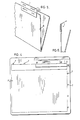
- a template generally indicated at 1 is used to guide manual application of an adhesive label L to a panel P of a file folder F.
- the label is applied such that it wraps around the edge of the panel from one side to the other of the panel.
- label L is coded by means of a pair of identical codes which are upside down and backwards with respect to one another at each side of the label. Each of these codes is machine readable and requires accurate location with respect to the file edge to enable valid machine reading of the code.
- the codes are positioned essentially identically on each half of the label, so that when the label is fully applied to the file panel, it is subdivided such that equal portions of the label are located on either side of the panel.
- template 1 comprises a file panel supporting portion 3, pegs 7 and 7a for positioning the file panel on the panel supporting portion and label locating jig 11 along an edge of the panel supporting portion.
- the panel supporting portion has a generally planar surface 5 where the file panel sits when it is in position for label application. It will be noted that the panel supporting portion of the template is open on two sides to permit easy positioning of the file panel on the supporting surface and although, Figure 1 shows the application of the label along a side edge of the file panel, the label may also be applied along either the bottom or top edge of the panel.
- Label jig 11 which has a stair-like configuration, includes a first riser 13, a second riser 15 which is raised relative to the first riser to provide a label edge guide and a generally horizontal step or tread portion 17 which separates the two vertical risers and which extends from the top of the first riser to the base of the second riser.
- the first riser is in line with pegs 7 provided on the same side of the template as the label jig, so that when the file panel is properly positioned on the template flushly to the pegs, the panel edge lies against riser 13.
- a second generally horizontal step or tread portion 19 which extends from the first riser into the panel supporting portion of the template.
- the panel supporting portion of the template is recessed at 9 to receive step portion 19, the top surface of which is coplanar with the surface 5 of panel support 3.
- Label jig 11 is further provided with a right angle corner arrangement 21 having a small shoulder section 23 extending at right angles to the main body of the label jig.
- Shoulder 23 is aligned with the boundary line defined by pegs 7a on the same side of the template as shoulder 23 for purposes of file panel alignment during positioning of the file panel with respect to the label jig.
- the label jig also includes a further shoulder portion 25 extending at right angles to and at the same level as riser 15. Shoulder portion 25 is used as a guide to properly position the end of Label L along the file panel.
- the template is used for guiding manual application of the wrap-around label as best shown in Figures 2 through 4.
- the operation is preferably accomplished by first placing the label on the jig such that its outside longitudinal edge abuts riser 15 while the end edge of the label is forced up against shoulder 25.
- step 17 is surfaced with a material such as Polytetrafluorethylene (Teflon@), which has a low affinity for the adhesive on the label to enable easy moving of the label on the step into its proper position for application to the panel edge.
- Teflon@ Polytetrafluorethylene
- Step 19 which is also surfaced with the same material as step 17, provides a safety precaution against inadvertent, sticking of the unseated portion of the label on the panel supporting portion of the template. Therefore, if during placement of the label on the jig, the unseated portion is unadvertently bent down into contact with step 19, then this step, like step 17, will release any part of the label which comes into contact with it without significantly detracting from the adhesive properties of the label.
- the file panel is then move dinto position beneath the overhanging part of the label for application of the label, to one side of the file panel using the panel support 3 and guide pegs 7 and 7a to accurately position the file panel.
- one of the file panels is wider than the other panel to provide an extended edge region.
- the file folder is placed on the template such that this extended edge region abuts pegs 7 located along the same side of the template as the label jig.
- riser 13 of jig 3 is aligned with these pegs so that the extended edge region of the panel fits flushly against the riser.
- the end of the panel is forced up against pegs 7a to complete the locating of the file panel on the panel support.
- the label is secured to the panel by simply applying a downward pressure on the unseated part of the label which adheres to the exposed side of the panel beneath the label to accurately locate the label in position on the panel.
- both the file folder and the now-located label are removed from the template with the label jig releasing the other part of the label from step 17 without significantly detracting from its adhesive properties so that the label may be wrapped around the file panel edge and applied to the opposing side of the file panel as shown in Figures 5 and 6.
- each of the machine readable codes appears on opposing sides of the file panel equidistant from the edge to enable accurate machine reading of the codes from either side of the file folder.
- the width across step 17 is slightly greater than half of the label width so that the thickness of the file folder is taken into consideration for identical positioning of the codes on either side of the panel.
- the description above has related to the combination of the label jig, panel supporting portion and guiding pegs 7.
- the label jig could be used on its own and still provide an effective guide for the manual application of the label.
- the file panel edge is again forced up against riser 13 with the corner of the file panel being located in corner region 21 such that shoulder 23 of jig 11 provides a stop to longitudinally position the jig along the file panel without the requirement of pegs 7a.
- Such an arrangement may again include the forward step although it may be dispensed with, particularly if the surface used to support the file panel has low affinity for the adhesive on the label.
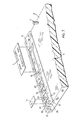
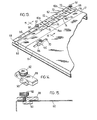
- Figure 7 shows a template comprising panel supporting portion 3, end pegs 7 and label locating jig 11 as earlier described.
- the template of Figure 7 additionally incorporates a further label locating jig 31 used to accurately locate a colour coded label L1 for wrapping around the same file panel edge as label L.
- Jig 31 is provided with a plurality of inserts 33, each of which is used to locate an individual colour coded label similar to label L1.
- a common riser 35 extends along the entire length of jig 31.
- Each of the inserts has its own label seating step region 37 and rear riser 39.
- a forward step region 41 coplanar with surface 5 of the panel support runs along the length of jig 31 and is again, common to all of the individual inserts 33.
- Jig 31 is used in essentially the same manner as jig 11 for locating the individual colour coded labels. Slightly more than half of the colour coded label is seated on step 37 which is again provided with a surface having low affinity for the adhesive on the label. The remaining part of label L1 which overhangs step 41 is exposed for application to one side of the file panel to locate the label in position on the panel. The file folder is then removed from the template with the seated part of label L1 being readily removable from step 37 to enable complete application of the label around the panel edge. It will be noted in this embodiment, that no pegs 7 are required along the side of the template where jigs 31 and 11 are located since risers 35 and 13 respectively, provide a stop against which the file panel edge is fitted.
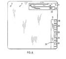
- FIG 8 The arrangement shown in Figure 8 is similar to the arrangement shown in Figure 7 with the exception that jigs 11 and 31 extend at right angles to one another on separate and distinct sides of the template.
- This template arrangement is used for file folders in which the top edge of the file folder is provided with a wrap around machine readable coded label and the side edge of the file folder is provided with colour coded labels or vice versa.
- jig 31 replaces pegs 7a along the side of the template at right angles to jig 11. Accordingly, riser 35 of jig 31 is aligned with shoulder 23 of jig 11.
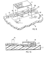
- Figures 9 and 10 show a template and jig arrangement used to accurately apply, a non-wrap-around label L1, to a file panel such that the longitudinal edge of the label aligns with the file panel edge.
- Label L1 is printed on one side only and is again, provided with a machine readable code which in this case is accurately located on the file panel for machine reading of the code when the edge of the label is flush with the file panel edge.
- Template 3 is essentially identical to the template described above and again, consists of a panel supporting surface 5 bound on one side by pegs 7 and on a second side by pegs 7a with the other two sides of the panel support being open for placement of the file panel on the supporting surface.
- Jig 40 which is used to guide the application of label L1 comprises a file panel edge guide 42, a label guide 46 and -a generally horizontal plateau 44 at right angles to and between the two guides. As is best shown in Figure 10, guides 42 and 46 are vertically aligned with one another.
- Jig 40 further includes a forward plateau 48, the top surface of which is coplanar with panel supporting surface 5.
- Label L1 is fitted on the label jig with its outside longitudinal edge against guide 46 and its end edge against shoulder 52. Again, it is quite difficult to initially accurately locate the label in this position so that plateau 44 which is used to seat part of the label, is surfaced with a material to which the adhesive on the back of the label has low affinity for enabling easy movement to the desired position.
- Pleateau 48 is surfaced with a similar material to once again, prevent inadvertent sticking of the unseated part of the label to the lower plateau.
- the file panel is slid beneath plateau 44 such that its outside edge abuts guide 42.
- Pegs 7 and 7a cooperate with the jig in squaring the file panel on the template.
- jig 40 can once again be used on its own, separately from the template or it can be used on the template in combination with a second jig such as jig 31 arranged on the same side of the template as jig 40 similar to the arrangement shown in Figure 7 or at right angles to jig 40, similar to the arrangement shown in Figure 8.
- any or all of the jig arrangements shown above can be used to accurately apply an adhesive coating over a code applied directly on the file panel or to a label at a file panel edge whether that label be a wrap-around or a non-wrap-around label.
- the method of applying the protective coating is essentially identical to the method of applying the label to the file panel.
- the cover itself is transparent and made from a material such as Mylar@, so that the code can be seen through the protective cover.
- the panel edge guide of the jigs is shown as being aligned with the guiding posts on the template.
- the lower riser on the jig can be recessed to the extent that it is located outwardly of the posts or pegs on the template in which case, the panel edge would not meet with the lower riser.
- the posts would be used on their own to guide the locating of the panel edge with respect to the jig.
- the first riser will be used as the file edge guide.
- each of the templates shown in Figures 1, 7 and 8 is generally set up in a somewhat permanent manner for different patterns of adhesive member applications along the edge of a file panel.
- a template is provided which can be setup in a number of different manners and which can be changed according to the pattern of labels desired.
- a template base or plate 60 which is preferably formed from steel and which may be finished with a bright zinc or similar non corrosive surface includes bend down top and bottom edges 62 as well as bend down side edges 64 which are slightly wider than the top and bottom edges.
- An I-shaped slot 66 runs completely across the template plate such that the widened end portions of the slot are located in the opposing bend down side edges 64.
- the template plate is further provided with a blind ended slot 70.
- a plurality of different segments as shown in Figures 12 and 13 are adapted to fit into slot 66 and to slide to essentially any desired position.
- These segments comprise a plurality of jig segments 72, spacer segments 82 and 82a of different width and locking segments 88.
- These segments may all be made from one aluminum extrusion cut at different points according to the length desired for each of the individual segments.
- the jig segments are then further cut out to provide a step-like construction as shown in segments 72.
- the locking segment is on the other hand drilled to provide a threaded bore for receiving a set screw 92
- All of the individual segments are provided with an undercut portion for fitting through the open ends 68 of slot 66.
- These undercut portions are shown at 80 for jig segments 72, at 86 and 86a for spacer segments 82 and 82a respectively and at 90 for locking segments 88.
- the cooperation between the undercut portion of each of the segments and the slot 60 enables the trapped segments to be moved along the slot.
- Each of the jig segments is provided with a file panel edge guide 74, a label seat portion 76 and a label edge guide 78.
- Each of the label seats is provided with a Teflon@ coating which may for instance be sprayed on the jig segments after cutting.
- Spacers 82 and 82a as well as locking segments 88 both have a constant level without any step-like construction. Accordingly, when either of these segments is fitted beside one of the jig segments, they rise above the label seat portion of the jig segments where they are co-planar with the top of the label edge guide. Therefore, each of the segments 82 and 88 acts as a further label edge guide at generally right angles to the first label edge guide on each of the jig segments. This feature is clearly shown in Figure 13.
- the jig segments can be moved to a plurality of different adhesive member guiding positions according to the positioning of spacer 82.
- jig segments 72 can be positioned immediately adjacent one another without using any spacers whatsoever in the event that an elongated label is required along the file edge.
- additional jig and spacer segments to those shown in the drawings may be used for a more lengthy label at the panel edge.
- the segments Once the segments have been moved to the appropriate positions they are then releasably locked in those appropriate positions through locking segments 88 which are secured by tightening set screws 92 onto the template base.
- locking segments 88 are releasable from their secured positions to rearrange the pattern of jig segments and spacers.
- the template is provided with an adjustable stop arrangement comprising a guide member 95 threadably secured to a base portion 96 on opposing sides of slot 70.
- This adjustable stop arrangement is used as a guide to the file panel edge which is at 90 degrees to the edge of the file located along the jig segments.
- the adjustable stop can be moved to any desired position along slot 70 and fixed in that position by tightening guide 94 downwardly onto base 96 and clamping the template between the guide and its base.
- the Teflon@ coating on the jig segments has a relatively low affinity for the types of adhesives found on labels and the like. Therefore the jig segments which are used in locating labels and label covers for manual application along the edge of a file do not noticeably detract from the adhesive properties of the label after it has been removed from the label seat portion of the jig segment.
- a strip 61 Teflon@ adjacent slot 66 which file panel supporting portion of the template also has a relatively low affinity for the adhesive on the labels so that if the label is inadvertantly bent down into contact with the Teflon@ strip on the file panel support it can easily be lifted with substantially no effect to the adhesive properties of the label.
Landscapes
- Labeling Devices (AREA)
- Electrochromic Elements, Electrophoresis, Or Variable Reflection Or Absorption Elements (AREA)
- Pharmaceuticals Containing Other Organic And Inorganic Compounds (AREA)
- Suspension Of Electric Lines Or Cables (AREA)
- Vehicle Body Suspensions (AREA)
Claims (16)
Priority Applications (1)
| Application Number | Priority Date | Filing Date | Title |
|---|---|---|---|
| AT81305353T ATE8357T1 (de) | 1980-11-12 | 1981-11-11 | Schablone zum aufbringen von kennzeichen mit der hand. |
Applications Claiming Priority (2)
| Application Number | Priority Date | Filing Date | Title |
|---|---|---|---|
| US20516880A | 1980-11-12 | 1980-11-12 | |
| US205168 | 1980-11-12 |
Publications (2)
| Publication Number | Publication Date |
|---|---|
| EP0052018A1 EP0052018A1 (de) | 1982-05-19 |
| EP0052018B1 true EP0052018B1 (de) | 1984-07-11 |
Family
ID=22761093
Family Applications (1)
| Application Number | Title | Priority Date | Filing Date |
|---|---|---|---|
| EP81305353A Expired EP0052018B1 (de) | 1980-11-12 | 1981-11-11 | Schablone zum Aufbringen von Kennzeichen mit der Hand |
Country Status (6)
| Country | Link |
|---|---|
| EP (1) | EP0052018B1 (de) |
| JP (1) | JPS57114430A (de) |
| AT (1) | ATE8357T1 (de) |
| AU (1) | AU548428B2 (de) |
| CA (1) | CA1140085A (de) |
| DE (1) | DE3164766D1 (de) |
Families Citing this family (5)
| Publication number | Priority date | Publication date | Assignee | Title |
|---|---|---|---|---|
| US5501260A (en) * | 1993-09-28 | 1996-03-26 | Young; Edward R. | Method using a jig for affixing an adaptor to the bottom of a business card |
| US5569150A (en) * | 1994-11-25 | 1996-10-29 | Xerox Corporation | Assembly apparatus |
| US5644963A (en) * | 1996-05-17 | 1997-07-08 | George Seater, Jr. | Roofing shingle cutting guide |
| CN105501593A (zh) * | 2015-12-25 | 2016-04-20 | 苏州井上橡塑有限公司 | 塑料制品产品定位标签粘贴治具 |
| US10471764B2 (en) * | 2016-12-29 | 2019-11-12 | Kabushiki Kaisha Toshiba | Sheet processing apparatus and sheet processing method |
Family Cites Families (6)
| Publication number | Priority date | Publication date | Assignee | Title |
|---|---|---|---|---|
| FR903771A (fr) * | 1943-12-02 | 1945-10-15 | Procédé de fixation sans surépaisseur d'un document transparent sur une fiche ou similaire | |
| US3399097A (en) * | 1965-10-20 | 1968-08-27 | Lifetime Foam Products Inc | Label positioning apparatus |
| CH497318A (de) * | 1968-12-18 | 1970-10-15 | Mappei Org Mittel Gmbh | Formatbogen mit Selbstklebeschicht, zur Bildung von Karteiblattreitern |
| US3937493A (en) * | 1974-09-30 | 1976-02-10 | The Smead Manufacturing Company | Color coded labels and file folders |
| DE2545271A1 (de) * | 1975-10-09 | 1977-04-14 | Regis Gmbh | Markierungsgeraet zum anbringen von ordnungsmerkmalen auf den kopfleisten von karteikarten und mikrofilmstreifenkarten |
| DE2613268C3 (de) * | 1976-03-27 | 1980-06-04 | Mappei-Organisationsmittel Gmbh, 5600 Wuppertal | Vorrichtung zum Anbringen selbstklebender Etiketten |
-
1980
- 1980-12-23 CA CA000367396A patent/CA1140085A/en not_active Expired
-
1981
- 1981-11-11 DE DE8181305353T patent/DE3164766D1/de not_active Expired
- 1981-11-11 EP EP81305353A patent/EP0052018B1/de not_active Expired
- 1981-11-11 AT AT81305353T patent/ATE8357T1/de not_active IP Right Cessation
- 1981-11-12 AU AU77433/81A patent/AU548428B2/en not_active Ceased
- 1981-11-12 JP JP56181684A patent/JPS57114430A/ja active Pending
Also Published As
| Publication number | Publication date |
|---|---|
| AU7743381A (en) | 1982-05-20 |
| DE3164766D1 (en) | 1984-08-16 |
| AU548428B2 (en) | 1985-12-12 |
| JPS57114430A (en) | 1982-07-16 |
| CA1140085A (en) | 1983-01-25 |
| EP0052018A1 (de) | 1982-05-19 |
| ATE8357T1 (de) | 1984-07-15 |
Similar Documents
| Publication | Publication Date | Title |
|---|---|---|
| US4369582A (en) | Manual label applying template | |
| US4965943A (en) | Workpiece joint-forming template system | |
| DE69606615T2 (de) | Vorrichtung zum anbringen und beschneiden von kantenmaterial an plattenförmigen werkstücken | |
| US4226143A (en) | Method of making steel rule type piercing and blanking dies | |
| DE860249T1 (de) | Verfahren zum Schneiden von bahnförmigen Materialien | |
| EP0052018B1 (de) | Schablone zum Aufbringen von Kennzeichen mit der Hand | |
| DE3331384A1 (de) | Verfahren zum herstellen von mehrfarbigen kennzeichnungen und schichtmaterial hierfuer | |
| US5694853A (en) | Alignment method for accurately registering sheet material on a plate and fixture therefor | |
| DE102008059838A1 (de) | Führungsschiene für eine Säge | |
| US2539609A (en) | Method of composing type lines for reproduction | |
| US3769140A (en) | Adjustable web splicing device | |
| US2696867A (en) | Apparatus and method for copy preparation and make-up | |
| US4503618A (en) | Plaque alignment tool | |
| US5225266A (en) | Specimen slide | |
| EP0080337B1 (de) | Einrichtung zur Verwendung von Folien zur Trockenübertragung von Zeichen | |
| EP1066139B1 (de) | Fliesenschneidemaschine mit fliessenpositionier-parallel- und diagonal-liniengitter | |
| US5697138A (en) | Apparatus and method for fabricating trimmed letters | |
| DE102019219192B4 (de) | Verfahren zur Erstellung eines zusammengehaltenen Papierstapels mit Schnittveredelung und verdecktem Aufdruck | |
| US2150104A (en) | Apparatus for making book covers | |
| CN219294134U (zh) | 一种多尺寸修边装置 | |
| DE3027658C2 (de) | Verfahren zur Herstellung einer rechteckigen Identitätskarte | |
| US2737239A (en) | Apparatus for correction and make-up of type matter for photographic printing | |
| GB2125735A (en) | Book finishing | |
| DE2907719C2 (de) | Terminplaner | |
| NO163287B (no) | Fiberforsterket kompositt og fremgangsmaate til fremstilling derav. |
Legal Events
| Date | Code | Title | Description |
|---|---|---|---|
| PUAI | Public reference made under article 153(3) epc to a published international application that has entered the european phase |
Free format text: ORIGINAL CODE: 0009012 |
|
| AK | Designated contracting states |
Designated state(s): AT BE CH DE FR GB IT NL SE |
|
| 17P | Request for examination filed |
Effective date: 19820809 |
|
| ITF | It: translation for a ep patent filed | ||
| GRAA | (expected) grant |
Free format text: ORIGINAL CODE: 0009210 |
|
| AK | Designated contracting states |
Designated state(s): AT BE CH DE FR GB IT LI NL SE |
|
| REF | Corresponds to: |
Ref document number: 8357 Country of ref document: AT Date of ref document: 19840715 Kind code of ref document: T |
|
| REF | Corresponds to: |
Ref document number: 3164766 Country of ref document: DE Date of ref document: 19840816 |
|
| ET | Fr: translation filed | ||
| PGFP | Annual fee paid to national office [announced via postgrant information from national office to epo] |
Ref country code: DE Payment date: 19841105 Year of fee payment: 4 |
|
| PGFP | Annual fee paid to national office [announced via postgrant information from national office to epo] |
Ref country code: CH Payment date: 19841113 Year of fee payment: 4 |
|
| PGFP | Annual fee paid to national office [announced via postgrant information from national office to epo] |
Ref country code: FR Payment date: 19841129 Year of fee payment: 4 |
|
| BECA | Be: change of holder's address |
Free format text: 840711 *WRIGHT LINE OF CANADA LTD-WRIGHT LINE DU CANADA LTEE130 SPARKS AVENUE, WILLOWDALE ONTARIO |
|
| BECH | Be: change of holder |
Free format text: 840711 *WRIGHT LINE OF CANADA LTD-WRIGHT LINE DU CANADA LTEE |
|
| PGFP | Annual fee paid to national office [announced via postgrant information from national office to epo] |
Ref country code: SE Payment date: 19841231 Year of fee payment: 4 Ref country code: BE Payment date: 19841231 Year of fee payment: 4 |
|
| PLBE | No opposition filed within time limit |
Free format text: ORIGINAL CODE: 0009261 |
|
| STAA | Information on the status of an ep patent application or granted ep patent |
Free format text: STATUS: NO OPPOSITION FILED WITHIN TIME LIMIT |
|
| 26N | No opposition filed | ||
| PGFP | Annual fee paid to national office [announced via postgrant information from national office to epo] |
Ref country code: AT Payment date: 19861128 Year of fee payment: 6 |
|
| PGFP | Annual fee paid to national office [announced via postgrant information from national office to epo] |
Ref country code: NL Payment date: 19871130 Year of fee payment: 7 |
|
| PG25 | Lapsed in a contracting state [announced via postgrant information from national office to epo] |
Ref country code: GB Effective date: 19881111 Ref country code: AT Effective date: 19881111 |
|
| PG25 | Lapsed in a contracting state [announced via postgrant information from national office to epo] |
Ref country code: SE Effective date: 19881112 |
|
| PG25 | Lapsed in a contracting state [announced via postgrant information from national office to epo] |
Ref country code: LI Effective date: 19881130 Ref country code: CH Effective date: 19881130 Ref country code: BE Effective date: 19881130 |
|
| BERE | Be: lapsed |
Owner name: WRIGHT LINE OF CANADA LTD-WRIGHT LINE DU CANADA L Effective date: 19881130 |
|
| PG25 | Lapsed in a contracting state [announced via postgrant information from national office to epo] |
Ref country code: NL Effective date: 19890601 |
|
| NLV4 | Nl: lapsed or anulled due to non-payment of the annual fee | ||
| GBPC | Gb: european patent ceased through non-payment of renewal fee | ||
| PG25 | Lapsed in a contracting state [announced via postgrant information from national office to epo] |
Ref country code: FR Free format text: LAPSE BECAUSE OF NON-PAYMENT OF DUE FEES Effective date: 19890731 |
|
| REG | Reference to a national code |
Ref country code: CH Ref legal event code: PL |
|
| PG25 | Lapsed in a contracting state [announced via postgrant information from national office to epo] |
Ref country code: DE Effective date: 19890801 |
|
| REG | Reference to a national code |
Ref country code: FR Ref legal event code: ST |
|
| EUG | Se: european patent has lapsed |
Ref document number: 81305353.5 Effective date: 19890726 |