EP0051727A1 - Branchement de guides de lumière de diamètres différents - Google Patents
Branchement de guides de lumière de diamètres différents Download PDFInfo
- Publication number
- EP0051727A1 EP0051727A1 EP81107398A EP81107398A EP0051727A1 EP 0051727 A1 EP0051727 A1 EP 0051727A1 EP 81107398 A EP81107398 A EP 81107398A EP 81107398 A EP81107398 A EP 81107398A EP 0051727 A1 EP0051727 A1 EP 0051727A1
- Authority
- EP
- European Patent Office
- Prior art keywords
- branching
- optical fiber
- core
- light
- diameter
- Prior art date
- Legal status (The legal status is an assumption and is not a legal conclusion. Google has not performed a legal analysis and makes no representation as to the accuracy of the status listed.)
- Withdrawn
Links
Images

Classifications
-
- G—PHYSICS
- G02—OPTICS
- G02B—OPTICAL ELEMENTS, SYSTEMS OR APPARATUS
- G02B6/00—Light guides; Structural details of arrangements comprising light guides and other optical elements, e.g. couplings
- G02B6/24—Coupling light guides
- G02B6/26—Optical coupling means
- G02B6/28—Optical coupling means having data bus means, i.e. plural waveguides interconnected and providing an inherently bidirectional system by mixing and splitting signals
- G02B6/2804—Optical coupling means having data bus means, i.e. plural waveguides interconnected and providing an inherently bidirectional system by mixing and splitting signals forming multipart couplers without wavelength selective elements, e.g. "T" couplers, star couplers
Definitions
- the invention relates to an optical fiber branching with at least three optical fibers (LLF), each consisting of a light-guiding core and a cladding, the refractive index of which is smaller than the refractive index of the core, the polished end face of a common optical fiber being glued to the polished end faces of the branching optical fibers is connected, and wherein the diameter d of the cores of the branching optical fibers are smaller than the diameter D of the core of the common optical fiber.
- LLC optical fiber branching with at least three optical fibers
- Lichtlei.terbranchungen are mainly used when a common optical fiber mostly longer length is to be connected with several light transmitters, several light receivers or additional measuring and control devices.
- An optical fiber branching of the known type has the disadvantage that when light is fed in with uniform excitation of all modes from one of the branching optical fibers into the common optical fiber, at best half of the light energy supplied in the branching fiber can be fed into the common optical fiber. This disadvantage arises from the fact that only half the cross-section is available at the junction of the fibers of the branching optical fibers.
- the invention has for its object to provide an optical fiber branch, in which as large a portion of the light coming from the branching optical fibers can be coupled into the common optical fiber, or, in other words, to specify a low-loss optical light multiplexer.
- the advantage that can be achieved with the invention is, in particular, that the choice of the diameter ratios of the core of common and branching optical fibers means that the light loss can be reduced as desired and theoretically avoided completely.
- Another advantage is that the attenuation for light retroreflecting from the common optical fiber, as can occur due to flaws in this fiber or other reflection points, is significantly greater than with known branches. This largely reduces interference which the reflection can cause in lasers used as light sources on the branching fibers.
- a branch that particularly strongly attenuates the retroreflection, as it arises when monomode fiber is used for the branching LLF, can thus also be used as an optical isolator.
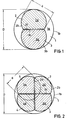
- an optical fiber branch is shown schematically in a cross section near the junction between the common optical fiber LLF 1 and the two branching LLF 2 and 3.
- This and the following representations only take into account those that conduct light Fiber cores, but not the sheaths surrounding the cores, which are also essential for light conduction, made of a material whose refractive index is smaller than that of the fiber cores.
- the pclosed end surface 1a of the fiber core with the diameter D is partially visible, its edge, which is followed by the jacket (not shown), is designated 1b.
- the end surfaces of the cores of the branching LLF 2 and 3 are glued onto the end surface 1a, the shape of which roughly corresponds to the cut surfaces 2a and 3a shown.
- the diameter of these unprocessed cores is denoted by d. It is smaller than the diameter D of the core 1 of the common LLF.
- surfaces 2c and 3c are machined obliquely to the longitudinal axis of the fibers, for example by grinding and polishing. It can be seen that the fiber jackets, not shown, must also be limited by the extensions of the surfaces 2c and 3c.
- the loss of light energy occurring at the end face 2a or 3a of a light-guiding LLF 2 or 3 is available, the larger the more core material has to be removed in the production of a light guide branch, the greater.
- the core cross section of the branching LLF at the coupling point is only half of the original cross-sectional area, and the light loss is therefore at least 50% or 3 db.
- the core diameter D of the common LLF 1 is 50 ⁇ m, that of the branching LLF 2 and 3 is approximately 30 ⁇ m.
- the assumption mentioned applies only approximately to step index fibers.
- the distribution of the light power over the cross-sectional area of the fiber core is proportional to the refractive index, so the proportion of the light power guided in the vicinity of the longitudinal axis of the core is significantly greater than according to the simplified first assumption. This results in more favorable conditions for the relationship between damping and small reductions in the cross-sectional area.
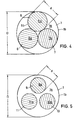
- FIG. 3 of the LIF 6 and 7 A further embodiment is shown schematically in FIG. 3 of the LIF 6 and 7 Vietnameser sinen.
- the branching LIF 6 and 7 have a core diameter d that is just half 30, like the core diameter D of the common LIF i.
- the cross section of the cores 6a and 7a no longer needs to be processed, and light losses due to a reduction in cross section no longer occur.
- This configuration is therefore particularly suitable for optical fiber branches with two branching LLFs.
- the core diameter d of the three branching LLF 6, 7 and 8 must here be somewhat smaller than half the core diameter D of the common LLF 1, which can still be achieved with commercially available multimode fibers.
- FIG. 5 Another embodiment is shown in FIG. 5.
- the core diameter d of the three branching LLFs 9, 10 and 11 in the example here is considerably smaller than half the core diameter D of the common LLF1.
- This version can also be realized with larger numbers of branching LLFs if monomode fibers are selected as the branching LLFs Core diameter d in the order of 6 to 12 microns depending on the light wavelength used.
Landscapes
- Physics & Mathematics (AREA)
- General Physics & Mathematics (AREA)
- Optics & Photonics (AREA)
- Optical Couplings Of Light Guides (AREA)
Applications Claiming Priority (2)
| Application Number | Priority Date | Filing Date | Title |
|---|---|---|---|
| DE3042563 | 1980-11-12 | ||
| DE19803042563 DE3042563A1 (de) | 1980-11-12 | 1980-11-12 | Lichtleiterverzweigung aus lichtleitfasern unterschiedlichen durchmessers |
Publications (1)
| Publication Number | Publication Date |
|---|---|
| EP0051727A1 true EP0051727A1 (fr) | 1982-05-19 |
Family
ID=6116529
Family Applications (1)
| Application Number | Title | Priority Date | Filing Date |
|---|---|---|---|
| EP81107398A Withdrawn EP0051727A1 (fr) | 1980-11-12 | 1981-09-18 | Branchement de guides de lumière de diamètres différents |
Country Status (4)
| Country | Link |
|---|---|
| EP (1) | EP0051727A1 (fr) |
| JP (1) | JPS57112709A (fr) |
| DE (1) | DE3042563A1 (fr) |
| SE (1) | SE8106618L (fr) |
Cited By (6)
| Publication number | Priority date | Publication date | Assignee | Title |
|---|---|---|---|---|
| EP0073314A1 (fr) * | 1981-08-29 | 1983-03-09 | Philips Kommunikations Industrie AG | Système de transmission pour une utilisation multiple bidirectionnelle d'une fibre optique |
| EP0101842A2 (fr) * | 1982-07-28 | 1984-03-07 | Siemens Aktiengesellschaft | Coupleur fibre optique avec âme biseautée |
| EP0288231A1 (fr) * | 1987-04-20 | 1988-10-26 | Mitsubishi Rayon Co., Ltd. | Coupleur optique et son procédé de fabrication |
| EP0291404A1 (fr) * | 1987-05-11 | 1988-11-17 | Photonetics | Dispositif pour la détection de vibrations comportant une fibre optique multimode comme élément sensible |
| GB2254934A (en) * | 1991-04-10 | 1992-10-21 | Messerschmitt Boelkow Blohm | Fibre optic 3x3 coupler |
| DE19532805A1 (de) * | 1995-08-25 | 1997-02-27 | Nichimen Europ Plc Zweignieder | Verbindung optischer Fasern |
Families Citing this family (4)
| Publication number | Priority date | Publication date | Assignee | Title |
|---|---|---|---|---|
| US4755021A (en) * | 1982-08-02 | 1988-07-05 | Andrew Corporation | Self-aligning optical fiber directional coupler and fiber-ring optical rotation sensor using same |
| JPS59154608U (ja) * | 1983-03-31 | 1984-10-17 | 矢野 留男 | 垂直度設定用重錘 |
| JPS6021705U (ja) * | 1983-07-19 | 1985-02-14 | アルプス電気株式会社 | 光分岐・結合器 |
| JPH0695169B2 (ja) * | 1983-12-27 | 1994-11-24 | 株式会社東芝 | スター・カプラ |
Citations (4)
| Publication number | Priority date | Publication date | Assignee | Title |
|---|---|---|---|---|
| DE2653815A1 (de) * | 1975-11-28 | 1977-06-02 | Thomson Csf | Koppler zur verbindung eines beliebigen lichtleiters mit allen anderen lichtleitern eines buendels |
| DE2744108A1 (de) * | 1976-10-01 | 1978-04-06 | Thomson Csf | Mehrkanalkoppler fuer lichtleitfaserverbindungen |
| DE2717535A1 (de) * | 1977-04-20 | 1978-11-02 | Siemens Ag | Verfahren zur herstellung einer lichtwellenleiter-verzweigung |
| US4232385A (en) * | 1977-07-12 | 1980-11-04 | Her Majesty The Queen In Right Of Canada, As Represented By The Minister Of National Defence | Frequency division multiplexing system for optical transmission of broadband signals |
-
1980
- 1980-11-12 DE DE19803042563 patent/DE3042563A1/de not_active Withdrawn
-
1981
- 1981-09-18 EP EP81107398A patent/EP0051727A1/fr not_active Withdrawn
- 1981-11-09 SE SE8106618A patent/SE8106618L/ not_active Application Discontinuation
- 1981-11-10 JP JP17914781A patent/JPS57112709A/ja active Pending
Patent Citations (4)
| Publication number | Priority date | Publication date | Assignee | Title |
|---|---|---|---|---|
| DE2653815A1 (de) * | 1975-11-28 | 1977-06-02 | Thomson Csf | Koppler zur verbindung eines beliebigen lichtleiters mit allen anderen lichtleitern eines buendels |
| DE2744108A1 (de) * | 1976-10-01 | 1978-04-06 | Thomson Csf | Mehrkanalkoppler fuer lichtleitfaserverbindungen |
| DE2717535A1 (de) * | 1977-04-20 | 1978-11-02 | Siemens Ag | Verfahren zur herstellung einer lichtwellenleiter-verzweigung |
| US4232385A (en) * | 1977-07-12 | 1980-11-04 | Her Majesty The Queen In Right Of Canada, As Represented By The Minister Of National Defence | Frequency division multiplexing system for optical transmission of broadband signals |
Non-Patent Citations (2)
| Title |
|---|
| IBM Technical Disclosure Bulletin Band 23, Nr. 4, September 1980 J.D. CROW et al. "Nonsymmetric Optical Star Coupler" seite 1686 * |
| Optische Nachrichtentechnik Band 31, Nr. 6, 1978 U. KALMBACH et al. "Abzweig fur Lichtleitfasern" seiten 423 bis 425 * |
Cited By (7)
| Publication number | Priority date | Publication date | Assignee | Title |
|---|---|---|---|---|
| EP0073314A1 (fr) * | 1981-08-29 | 1983-03-09 | Philips Kommunikations Industrie AG | Système de transmission pour une utilisation multiple bidirectionnelle d'une fibre optique |
| EP0101842A2 (fr) * | 1982-07-28 | 1984-03-07 | Siemens Aktiengesellschaft | Coupleur fibre optique avec âme biseautée |
| EP0101842A3 (fr) * | 1982-07-28 | 1986-07-30 | Siemens Aktiengesellschaft | Coupleur fibre optique avec âme biseautée |
| EP0288231A1 (fr) * | 1987-04-20 | 1988-10-26 | Mitsubishi Rayon Co., Ltd. | Coupleur optique et son procédé de fabrication |
| EP0291404A1 (fr) * | 1987-05-11 | 1988-11-17 | Photonetics | Dispositif pour la détection de vibrations comportant une fibre optique multimode comme élément sensible |
| GB2254934A (en) * | 1991-04-10 | 1992-10-21 | Messerschmitt Boelkow Blohm | Fibre optic 3x3 coupler |
| DE19532805A1 (de) * | 1995-08-25 | 1997-02-27 | Nichimen Europ Plc Zweignieder | Verbindung optischer Fasern |
Also Published As
| Publication number | Publication date |
|---|---|
| SE8106618L (sv) | 1982-05-13 |
| JPS57112709A (en) | 1982-07-13 |
| DE3042563A1 (de) | 1982-05-19 |
Similar Documents
| Publication | Publication Date | Title |
|---|---|---|
| EP0037057B1 (fr) | Branchement de guides d'ondes optiquesà faibles effets de polarisation | |
| EP0012189B1 (fr) | Elément coupleur pour dériver une fraction de lumière d'un guide d'ondes optique comprenant une fibre entourée d'une gaine | |
| DE69628373T2 (de) | Optischer Koppler mit faseroptischen Steckerstiften | |
| EP0102113B1 (fr) | Connecteur en étoile optique | |
| DE2745940A1 (de) | Optisches schaltkreiselement | |
| DE2938649A1 (de) | Vorrichtung und verfahren zur signaluebertragung in lichtleitern | |
| DE3414724C2 (fr) | ||
| DE2842535A1 (de) | Abzweigelement | |
| EP0051727A1 (fr) | Branchement de guides de lumière de diamètres différents | |
| DE3019955A1 (de) | Kopplungselement fuer lichtwellenleiter | |
| DE3036618A1 (de) | Steuerelement zum steuern einer lichtuebertragung zwischen lichtwellenleitern | |
| DE3218023A1 (de) | Optischer multiplexer | |
| EP0416640B1 (fr) | Méthode de fabrication d'un coupleur optique fusionné et coupleur ainsi fabriqué | |
| EP0315270A2 (fr) | Elément optique à portes multiples avec un modulateur acousto-optique | |
| EP0176820A2 (fr) | Elément d'un connecteur pour des connexions séparables des guides d'ondes lumineuses | |
| DE3741284C2 (de) | Faseroptischer Mehrfachkoppler | |
| DE2655382A1 (de) | Verteilanordnung/mischer fuer optische nachrichtenuebertragungssysteme | |
| DE2851654A1 (de) | Koppelelement zum auskoppeln eines lichtanteils aus einem optischen wellenleiter und wiedereinkoppeln desselben in einen abzweigenden optischen wellenleiter sowie verfahren zur herstellung des elements | |
| EP0073314A1 (fr) | Système de transmission pour une utilisation multiple bidirectionnelle d'une fibre optique | |
| DE2927025C2 (fr) | ||
| DE2938526A1 (de) | Optischer 4-tor-koppler | |
| EP0934543B1 (fr) | Dispositif pour injecter de la lumiere a l'extremite d'une fibre multimode | |
| EP1342115A2 (fr) | Cable a fibres optiques et procede pour transmettre des signaux optiques, notamment selon la technique de multiplexage a repartition en longueur d'ondes | |
| DE2937580A1 (de) | Kopplungsanordnung fuer lichtwellenleiter | |
| EP0101842A2 (fr) | Coupleur fibre optique avec âme biseautée |
Legal Events
| Date | Code | Title | Description |
|---|---|---|---|
| PUAI | Public reference made under article 153(3) epc to a published international application that has entered the european phase |
Free format text: ORIGINAL CODE: 0009012 |
|
| AK | Designated contracting states |
Designated state(s): FR GB IT |
|
| RAP1 | Party data changed (applicant data changed or rights of an application transferred) |
Owner name: PHILIPS KOMMUNIKATIONS INDUSTRIE AG |
|
| STAA | Information on the status of an ep patent application or granted ep patent |
Free format text: STATUS: THE APPLICATION IS DEEMED TO BE WITHDRAWN |
|
| 18D | Application deemed to be withdrawn |
Effective date: 19830420 |
|
| RIN1 | Information on inventor provided before grant (corrected) |
Inventor name: RITTICH, DIETER, DIPL.-ING. Inventor name: KHOE, GIOK-DJAN, DIPL.-ING. Inventor name: NICIA, ANTONIUS, DIPL.-ING. |