EP0051129B1 - Kraftstoff-Einspritzdüse für Brennkraftmaschinen, insbesondere für Dieselmotoren - Google Patents
Kraftstoff-Einspritzdüse für Brennkraftmaschinen, insbesondere für Dieselmotoren Download PDFInfo
- Publication number
- EP0051129B1 EP0051129B1 EP81106991A EP81106991A EP0051129B1 EP 0051129 B1 EP0051129 B1 EP 0051129B1 EP 81106991 A EP81106991 A EP 81106991A EP 81106991 A EP81106991 A EP 81106991A EP 0051129 B1 EP0051129 B1 EP 0051129B1
- Authority
- EP
- European Patent Office
- Prior art keywords
- recess
- intermediate plate
- induction coil
- nozzle
- coil
- Prior art date
- Legal status (The legal status is an assumption and is not a legal conclusion. Google has not performed a legal analysis and makes no representation as to the accuracy of the status listed.)
- Expired
Links
- 238000002347 injection Methods 0.000 title claims description 6
- 239000007924 injection Substances 0.000 title claims description 6
- 239000000446 fuel Substances 0.000 title claims description 5
- 238000002485 combustion reaction Methods 0.000 title claims description 3
- 239000002775 capsule Substances 0.000 claims description 10
- 230000006698 induction Effects 0.000 claims description 10
- 239000000696 magnetic material Substances 0.000 claims description 2
- 239000002184 metal Substances 0.000 claims description 2
- 230000000717 retained effect Effects 0.000 claims 1
- 239000000853 adhesive Substances 0.000 description 6
- 230000001070 adhesive effect Effects 0.000 description 6
- 238000009825 accumulation Methods 0.000 description 1
- 238000004026 adhesive bonding Methods 0.000 description 1
- 238000011161 development Methods 0.000 description 1
- 230000018109 developmental process Effects 0.000 description 1
- 239000000463 material Substances 0.000 description 1
- 239000007769 metal material Substances 0.000 description 1
- 239000000203 mixture Substances 0.000 description 1
- 230000002787 reinforcement Effects 0.000 description 1
- 230000003014 reinforcing effect Effects 0.000 description 1
- 238000004804 winding Methods 0.000 description 1
Images
Classifications
-
- F—MECHANICAL ENGINEERING; LIGHTING; HEATING; WEAPONS; BLASTING
- F02—COMBUSTION ENGINES; HOT-GAS OR COMBUSTION-PRODUCT ENGINE PLANTS
- F02M—SUPPLYING COMBUSTION ENGINES IN GENERAL WITH COMBUSTIBLE MIXTURES OR CONSTITUENTS THEREOF
- F02M65/00—Testing fuel-injection apparatus, e.g. testing injection timing ; Cleaning of fuel-injection apparatus
- F02M65/005—Measuring or detecting injection-valve lift, e.g. to determine injection timing
Definitions
- the invention relates to a fuel injection nozzle according to the preamble of the main claim. It has been found that the bottom section of the intermediate plate supporting the induction coil is relatively thin and therefore insufficiently rigid. The stiffness is increased by the reinforcing ring on the inside of the base part. Despite this reinforcement, it cannot be ruled out that - due to the low rigidity - the induction coil glued into the recess will come loose and the function of the induction coil acting as a signal transmitter will be disturbed.
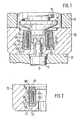
- FIG. 1 shows the first exemplary embodiment with a conically enlarged recess wall
- Figure 2 shows the second example with an annular groove in the recess wall.
- an intermediate plate 62 clamped between a nozzle body 10 and a nozzle holder 13 shows a valve needle 11 with a pressure pin 17, which cooperates with a pressure pin 18 loaded by a pressure spring 19.
- the intermediate plate 62 abutting the nozzle holder 13 has a ring 59 which receives the pressure pin 17.
- a rotationally symmetrical recess 61 is recessed with an end base 63 and a jacket-shaped wall 64 which widens conically towards the base 63.
- a capsule 65 made of magnetic material, in particular metal, consists of a sleeve 66 and an inner flange 67.
- the capsule 65 receives an induction coil 20 and is inserted into the recess 61 in such a way that the inner flange 67 connects the induction coil 20 to the bottom 63 the recess 61 keeps pressed.
- the capsule 65 is glued into the cutout 61 of the intermediate plate 62, the adhesive 68 filling the ring region, which is triangular in cross section, between the wall 64 and the outer casing 69 of the capsule 65.
- the intermediate plate 72 in FIG. 2 has a cylindrical wall 74 with a sawtooth-shaped annular groove 75 in cross section, the cross section of which widens towards the bottom 73.
- the capsule 65 holds the induction coil 20 pressed against the bottom 73 of the recess 71, and the adhesive 68 fills the area between the wall 74 and the outer casing 69 of the capsule 65 and the sawtooth-shaped annular groove 75.
Landscapes
- Engineering & Computer Science (AREA)
- Chemical & Material Sciences (AREA)
- Combustion & Propulsion (AREA)
- Mechanical Engineering (AREA)
- General Engineering & Computer Science (AREA)
- Fuel-Injection Apparatus (AREA)
Applications Claiming Priority (2)
| Application Number | Priority Date | Filing Date | Title |
|---|---|---|---|
| DE3040811 | 1980-10-30 | ||
| DE19803040811 DE3040811A1 (de) | 1980-10-30 | 1980-10-30 | Kraftstoff-einspritzduese fuer brennkraftmaschinen, insbesondere fuer dieselmotoren |
Publications (2)
| Publication Number | Publication Date |
|---|---|
| EP0051129A1 EP0051129A1 (de) | 1982-05-12 |
| EP0051129B1 true EP0051129B1 (de) | 1984-01-25 |
Family
ID=6115491
Family Applications (1)
| Application Number | Title | Priority Date | Filing Date |
|---|---|---|---|
| EP81106991A Expired EP0051129B1 (de) | 1980-10-30 | 1981-09-07 | Kraftstoff-Einspritzdüse für Brennkraftmaschinen, insbesondere für Dieselmotoren |
Country Status (4)
| Country | Link |
|---|---|
| US (1) | US4394823A (Direct) |
| EP (1) | EP0051129B1 (Direct) |
| JP (1) | JPS57102557A (Direct) |
| DE (2) | DE3040811A1 (Direct) |
Families Citing this family (3)
| Publication number | Priority date | Publication date | Assignee | Title |
|---|---|---|---|---|
| DE3326840A1 (de) * | 1983-07-26 | 1985-02-14 | Robert Bosch Gmbh, 7000 Stuttgart | Kraftstoff-einspritzduese fuer brennkraftmaschinen |
| DE3515264A1 (de) * | 1985-04-27 | 1986-11-27 | Robert Bosch Gmbh, 7000 Stuttgart | Kraftstoff-einspritzduese fuer brennkraftmaschinen |
| GB2260165A (en) * | 1991-10-01 | 1993-04-07 | Lucas Ind Plc | I.c. engine fuel injector |
Family Cites Families (2)
| Publication number | Priority date | Publication date | Assignee | Title |
|---|---|---|---|---|
| BE561146A (Direct) * | 1956-09-27 | |||
| DE3004424A1 (de) * | 1980-02-07 | 1981-08-13 | Robert Bosch Gmbh, 7000 Stuttgart | Kraftstoff-einspritzduesenhalter |
-
1980
- 1980-10-30 DE DE19803040811 patent/DE3040811A1/de not_active Withdrawn
-
1981
- 1981-09-07 DE DE8181106991T patent/DE3162039D1/de not_active Expired
- 1981-09-07 EP EP81106991A patent/EP0051129B1/de not_active Expired
- 1981-10-13 US US06/311,052 patent/US4394823A/en not_active Expired - Fee Related
- 1981-10-28 JP JP56171519A patent/JPS57102557A/ja active Granted
Also Published As
| Publication number | Publication date |
|---|---|
| JPS57102557A (en) | 1982-06-25 |
| DE3162039D1 (en) | 1984-03-01 |
| US4394823A (en) | 1983-07-26 |
| EP0051129A1 (de) | 1982-05-12 |
| DE3040811A1 (de) | 1982-06-16 |
| JPH031510B2 (Direct) | 1991-01-10 |
Similar Documents
| Publication | Publication Date | Title |
|---|---|---|
| EP0685643B1 (de) | Ventilnadel für ein elektromagnetisch betätigbares Ventil | |
| EP0352445B1 (de) | Elektromagnetisch betätigbares Ventil | |
| EP1789673B1 (de) | Einspritzventil zur kraftstoffeinspritzung | |
| DE3031619A1 (de) | Verfahren zum herstellen einer brennstoffeinspritzvorrichtung | |
| EP1825136B1 (de) | Einspritzventil | |
| DE2932480C2 (Direct) | ||
| DE19631066A1 (de) | Brennstoffeinspritzventil | |
| EP1114249B1 (de) | Brennstoffeinspritzventil | |
| DE4445358A1 (de) | Ventil und Verfahren zur Herstellung eines Ventiles | |
| EP0167819A1 (de) | Filter zum Reinigen von Flüssigkeiten | |
| EP0045530A2 (de) | Kraftstoff-Einspritzventil für Brennkraftmaschinen | |
| DE3031564A1 (de) | Elektromagnetisches kraftstoffeinspritzventil und verfahren zur herstellung eines elektromagnetischen kraftstoffeinspritzventiles | |
| DE102009000183A1 (de) | Brennstoffeinspritzventil | |
| EP0051129B1 (de) | Kraftstoff-Einspritzdüse für Brennkraftmaschinen, insbesondere für Dieselmotoren | |
| EP1336045B1 (de) | Injektorgehäuse mit einer aktoreinheit und dazwischenliegender dämpfungsscheibe | |
| EP0099991B1 (de) | Kraftstoff-Einspritzdüse für Brennkraftmaschinen | |
| DE3130238A1 (de) | "drucksensor fuer brennkraftmaschinen" | |
| DE102008043418A1 (de) | Kraftstoffeinspritzventil | |
| DE2842155A1 (de) | Kraftstoffeinspritzpumpe fuer brennkraftmaschinen | |
| EP0300198A1 (de) | Kraftstoffeinspritzdüse für Brennkraftmaschinen | |
| EP1797313B1 (de) | Brennstoffeinspritzventil | |
| DE19524148C1 (de) | Schwingungsaufnehmer | |
| EP0042915A2 (de) | Kraftstoffeinspritzventil für Brennkraftmaschinen | |
| EP0916050B1 (de) | Druckdichte baueinheit und verfahren zu deren herstellung | |
| DE3716072A1 (de) | Elektromagnetisch betaetigbares ventil |
Legal Events
| Date | Code | Title | Description |
|---|---|---|---|
| PUAI | Public reference made under article 153(3) epc to a published international application that has entered the european phase |
Free format text: ORIGINAL CODE: 0009012 |
|
| 17P | Request for examination filed |
Effective date: 19810907 |
|
| AK | Designated contracting states |
Designated state(s): DE FR GB |
|
| GRAA | (expected) grant |
Free format text: ORIGINAL CODE: 0009210 |
|
| AK | Designated contracting states |
Designated state(s): DE FR GB |
|
| REF | Corresponds to: |
Ref document number: 3162039 Country of ref document: DE Date of ref document: 19840301 |
|
| ET | Fr: translation filed | ||
| PLBE | No opposition filed within time limit |
Free format text: ORIGINAL CODE: 0009261 |
|
| STAA | Information on the status of an ep patent application or granted ep patent |
Free format text: STATUS: NO OPPOSITION FILED WITHIN TIME LIMIT |
|
| 26N | No opposition filed | ||
| PGFP | Annual fee paid to national office [announced via postgrant information from national office to epo] |
Ref country code: DE Payment date: 19891127 Year of fee payment: 9 |
|
| PGFP | Annual fee paid to national office [announced via postgrant information from national office to epo] |
Ref country code: GB Payment date: 19900905 Year of fee payment: 10 |
|
| PGFP | Annual fee paid to national office [announced via postgrant information from national office to epo] |
Ref country code: FR Payment date: 19900928 Year of fee payment: 10 |
|
| PG25 | Lapsed in a contracting state [announced via postgrant information from national office to epo] |
Ref country code: DE Effective date: 19910601 |
|
| PG25 | Lapsed in a contracting state [announced via postgrant information from national office to epo] |
Ref country code: GB Effective date: 19910907 |
|
| GBPC | Gb: european patent ceased through non-payment of renewal fee | ||
| PG25 | Lapsed in a contracting state [announced via postgrant information from national office to epo] |
Ref country code: FR Effective date: 19920529 |
|
| REG | Reference to a national code |
Ref country code: FR Ref legal event code: ST |