EP0050189B1 - Appareil pour collectionner et concentrer l'énergie de la lumière solaire - Google Patents
Appareil pour collectionner et concentrer l'énergie de la lumière solaire Download PDFInfo
- Publication number
- EP0050189B1 EP0050189B1 EP81105119A EP81105119A EP0050189B1 EP 0050189 B1 EP0050189 B1 EP 0050189B1 EP 81105119 A EP81105119 A EP 81105119A EP 81105119 A EP81105119 A EP 81105119A EP 0050189 B1 EP0050189 B1 EP 0050189B1
- Authority
- EP
- European Patent Office
- Prior art keywords
- optical element
- drive
- gimbal ring
- photosensors
- horizontal axis
- Prior art date
- Legal status (The legal status is an assumption and is not a legal conclusion. Google has not performed a legal analysis and makes no representation as to the accuracy of the status listed.)
- Expired
Links
- 230000003287 optical effect Effects 0.000 claims description 17
- 239000013307 optical fiber Substances 0.000 claims description 7
- 101100171060 Caenorhabditis elegans div-1 gene Proteins 0.000 claims description 4
- 101710170230 Antimicrobial peptide 1 Proteins 0.000 claims description 2
- 101710170231 Antimicrobial peptide 2 Proteins 0.000 claims description 2
- 239000002775 capsule Substances 0.000 description 14
- 230000003247 decreasing effect Effects 0.000 description 5
- 239000012141 concentrate Substances 0.000 description 3
- 239000000835 fiber Substances 0.000 description 3
- 241000251468 Actinopterygii Species 0.000 description 2
- 230000001932 seasonal effect Effects 0.000 description 2
- 230000002411 adverse Effects 0.000 description 1
- 239000003518 caustics Substances 0.000 description 1
- 238000006073 displacement reaction Methods 0.000 description 1
- 239000000428 dust Substances 0.000 description 1
- 238000009313 farming Methods 0.000 description 1
- 235000013305 food Nutrition 0.000 description 1
- 238000010438 heat treatment Methods 0.000 description 1
- 238000012423 maintenance Methods 0.000 description 1
- 230000000149 penetrating effect Effects 0.000 description 1
- 150000003839 salts Chemical class 0.000 description 1
- 235000015170 shellfish Nutrition 0.000 description 1
- 239000002689 soil Substances 0.000 description 1
- 239000000126 substance Substances 0.000 description 1
- XLYOFNOQVPJJNP-UHFFFAOYSA-N water Substances O XLYOFNOQVPJJNP-UHFFFAOYSA-N 0.000 description 1
Images

Classifications
-
- G—PHYSICS
- G01—MEASURING; TESTING
- G01S—RADIO DIRECTION-FINDING; RADIO NAVIGATION; DETERMINING DISTANCE OR VELOCITY BY USE OF RADIO WAVES; LOCATING OR PRESENCE-DETECTING BY USE OF THE REFLECTION OR RERADIATION OF RADIO WAVES; ANALOGOUS ARRANGEMENTS USING OTHER WAVES
- G01S3/00—Direction-finders for determining the direction from which infrasonic, sonic, ultrasonic, or electromagnetic waves, or particle emission, not having a directional significance, are being received
- G01S3/78—Direction-finders for determining the direction from which infrasonic, sonic, ultrasonic, or electromagnetic waves, or particle emission, not having a directional significance, are being received using electromagnetic waves other than radio waves
- G01S3/782—Systems for determining direction or deviation from predetermined direction
- G01S3/785—Systems for determining direction or deviation from predetermined direction using adjustment of orientation of directivity characteristics of a detector or detector system to give a desired condition of signal derived from that detector or detector system
- G01S3/786—Systems for determining direction or deviation from predetermined direction using adjustment of orientation of directivity characteristics of a detector or detector system to give a desired condition of signal derived from that detector or detector system the desired condition being maintained automatically
- G01S3/7861—Solar tracking systems
-
- F—MECHANICAL ENGINEERING; LIGHTING; HEATING; WEAPONS; BLASTING
- F24—HEATING; RANGES; VENTILATING
- F24S—SOLAR HEAT COLLECTORS; SOLAR HEAT SYSTEMS
- F24S23/00—Arrangements for concentrating solar-rays for solar heat collectors
- F24S23/12—Light guides
-
- F—MECHANICAL ENGINEERING; LIGHTING; HEATING; WEAPONS; BLASTING
- F24—HEATING; RANGES; VENTILATING
- F24S—SOLAR HEAT COLLECTORS; SOLAR HEAT SYSTEMS
- F24S23/00—Arrangements for concentrating solar-rays for solar heat collectors
- F24S23/30—Arrangements for concentrating solar-rays for solar heat collectors with lenses
-
- F—MECHANICAL ENGINEERING; LIGHTING; HEATING; WEAPONS; BLASTING
- F24—HEATING; RANGES; VENTILATING
- F24S—SOLAR HEAT COLLECTORS; SOLAR HEAT SYSTEMS
- F24S30/00—Arrangements for moving or orienting solar heat collector modules
- F24S30/40—Arrangements for moving or orienting solar heat collector modules for rotary movement
- F24S30/45—Arrangements for moving or orienting solar heat collector modules for rotary movement with two rotation axes
- F24S30/455—Horizontal primary axis
-
- H—ELECTRICITY
- H01—ELECTRIC ELEMENTS
- H01L—SEMICONDUCTOR DEVICES NOT COVERED BY CLASS H10
- H01L31/00—Semiconductor devices sensitive to infrared radiation, light, electromagnetic radiation of shorter wavelength or corpuscular radiation and specially adapted either for the conversion of the energy of such radiation into electrical energy or for the control of electrical energy by such radiation; Processes or apparatus specially adapted for the manufacture or treatment thereof or of parts thereof; Details thereof
- H01L31/04—Semiconductor devices sensitive to infrared radiation, light, electromagnetic radiation of shorter wavelength or corpuscular radiation and specially adapted either for the conversion of the energy of such radiation into electrical energy or for the control of electrical energy by such radiation; Processes or apparatus specially adapted for the manufacture or treatment thereof or of parts thereof; Details thereof adapted as photovoltaic [PV] conversion devices
- H01L31/054—Optical elements directly associated or integrated with the PV cell, e.g. light-reflecting means or light-concentrating means
- H01L31/0543—Optical elements directly associated or integrated with the PV cell, e.g. light-reflecting means or light-concentrating means comprising light concentrating means of the refractive type, e.g. lenses
-
- H—ELECTRICITY
- H01—ELECTRIC ELEMENTS
- H01L—SEMICONDUCTOR DEVICES NOT COVERED BY CLASS H10
- H01L31/00—Semiconductor devices sensitive to infrared radiation, light, electromagnetic radiation of shorter wavelength or corpuscular radiation and specially adapted either for the conversion of the energy of such radiation into electrical energy or for the control of electrical energy by such radiation; Processes or apparatus specially adapted for the manufacture or treatment thereof or of parts thereof; Details thereof
- H01L31/04—Semiconductor devices sensitive to infrared radiation, light, electromagnetic radiation of shorter wavelength or corpuscular radiation and specially adapted either for the conversion of the energy of such radiation into electrical energy or for the control of electrical energy by such radiation; Processes or apparatus specially adapted for the manufacture or treatment thereof or of parts thereof; Details thereof adapted as photovoltaic [PV] conversion devices
- H01L31/054—Optical elements directly associated or integrated with the PV cell, e.g. light-reflecting means or light-concentrating means
- H01L31/0547—Optical elements directly associated or integrated with the PV cell, e.g. light-reflecting means or light-concentrating means comprising light concentrating means of the reflecting type, e.g. parabolic mirrors, concentrators using total internal reflection
-
- F—MECHANICAL ENGINEERING; LIGHTING; HEATING; WEAPONS; BLASTING
- F24—HEATING; RANGES; VENTILATING
- F24S—SOLAR HEAT COLLECTORS; SOLAR HEAT SYSTEMS
- F24S25/00—Arrangement of stationary mountings or supports for solar heat collector modules
- F24S25/10—Arrangement of stationary mountings or supports for solar heat collector modules extending in directions away from a supporting surface
-
- Y—GENERAL TAGGING OF NEW TECHNOLOGICAL DEVELOPMENTS; GENERAL TAGGING OF CROSS-SECTIONAL TECHNOLOGIES SPANNING OVER SEVERAL SECTIONS OF THE IPC; TECHNICAL SUBJECTS COVERED BY FORMER USPC CROSS-REFERENCE ART COLLECTIONS [XRACs] AND DIGESTS
- Y02—TECHNOLOGIES OR APPLICATIONS FOR MITIGATION OR ADAPTATION AGAINST CLIMATE CHANGE
- Y02E—REDUCTION OF GREENHOUSE GAS [GHG] EMISSIONS, RELATED TO ENERGY GENERATION, TRANSMISSION OR DISTRIBUTION
- Y02E10/00—Energy generation through renewable energy sources
- Y02E10/40—Solar thermal energy, e.g. solar towers
- Y02E10/47—Mountings or tracking
-
- Y—GENERAL TAGGING OF NEW TECHNOLOGICAL DEVELOPMENTS; GENERAL TAGGING OF CROSS-SECTIONAL TECHNOLOGIES SPANNING OVER SEVERAL SECTIONS OF THE IPC; TECHNICAL SUBJECTS COVERED BY FORMER USPC CROSS-REFERENCE ART COLLECTIONS [XRACs] AND DIGESTS
- Y02—TECHNOLOGIES OR APPLICATIONS FOR MITIGATION OR ADAPTATION AGAINST CLIMATE CHANGE
- Y02E—REDUCTION OF GREENHOUSE GAS [GHG] EMISSIONS, RELATED TO ENERGY GENERATION, TRANSMISSION OR DISTRIBUTION
- Y02E10/00—Energy generation through renewable energy sources
- Y02E10/50—Photovoltaic [PV] energy
- Y02E10/52—PV systems with concentrators
-
- Y—GENERAL TAGGING OF NEW TECHNOLOGICAL DEVELOPMENTS; GENERAL TAGGING OF CROSS-SECTIONAL TECHNOLOGIES SPANNING OVER SEVERAL SECTIONS OF THE IPC; TECHNICAL SUBJECTS COVERED BY FORMER USPC CROSS-REFERENCE ART COLLECTIONS [XRACs] AND DIGESTS
- Y02—TECHNOLOGIES OR APPLICATIONS FOR MITIGATION OR ADAPTATION AGAINST CLIMATE CHANGE
- Y02P—CLIMATE CHANGE MITIGATION TECHNOLOGIES IN THE PRODUCTION OR PROCESSING OF GOODS
- Y02P60/00—Technologies relating to agriculture, livestock or agroalimentary industries
- Y02P60/12—Technologies relating to agriculture, livestock or agroalimentary industries using renewable energies, e.g. solar water pumping
Definitions
- the present invention relates to an apparatus for collecting and concentrating solar light energy comprising supporting means; an optical element movably supported there.on for collecting and concentrating solar light energy; an optical fiber cable having one end thereof located at the focus of the optical element and extending to the outside of the apparatus to transmit the collected solar light energy to the outside thereof; first drive means for rotating the optical element about a vertical axis; and second drive means for rotating the optical element about a horizontal axis, independently of the drive of the first drive means.
- the present invention relates to a solar light energy collecting means which are moved to automatically and successively follow the seasonal, daily and hourly changes in the location and angle of the sun, by drive means such as motors which can be driven with a small drive force (torque) by means of an electrical energy fed from, for example, a solar cell, while preventing the lens means from being accidentally displaced or moved by wind pressure or by waves.
- drive means such as motors which can be driven with a small drive force (torque) by means of an electrical energy fed from, for example, a solar cell, while preventing the lens means from being accidentally displaced or moved by wind pressure or by waves.
- the application of the present invention is directed, for example, to growing plants, or planktons, which are food for fish or other living things in the sea.
- the area of the ocean floor amounts to several times that of dry land. Moreover, the soil of the ocean floor is fertile.
- the depth of the ocean floor farm which is being planned now is about from 8 to 13 metres from the surface of the ocean, for example, at a coastal area. This depth is considered to be the maximum depth to obtain the solar light energy necessary for raising plants and it would be impossible to grow most plants in a place which is deeper than the above depth.
- the strength of the total amount of sunbeams penetrating the sea is decreased about 50% for every one meter in depth. Consequently, the amount of sunbeams in a place 8 to 13 metres from the surface of the sea, would be decreased from 2- 8 to 2- 13 , and would be further decreased in accordance with the degree of muddiness of the sea. Finally, it would be impossible to sufficiently raise plants in the sea due to lack of light.
- a collecting apparatus of the present invention can be advantageously used to provide solar light to areas deep in the sea.
- FR-A-2 384 216 describes an apparatus which collects and concentrates solar light energy and which uses lense means associated with optical fiber means in order to concentrate solar energy for heating purposes.
- This known apparatus is also electrically driven by a motor to which electric energy is fed from a commercial power supply involving the same problems which have been discussed above regarding the apparatus according to GB-A-15 23 532.
- the object of the present invention is, therefore, to provide a solar light energy collecting apparatus, including a sun follower, which can be mainly driven with a small drive torque by means of the electrical energy fed from a solar cell or the like and which is prevented from being accidentally displaced by the wind or waves when the apparatus is floating on the sea.
- This object according to the invention is accomplished by means of an apparatus of the type indicated above, which apparatus is characterized in that said optical element is a lense means enclosed by a transparent container, that the apparatus comprises solar cell means connected to the first and second drive means for feeding electrical energy thereto, and that the apparatus comprises detecting means movable and supported together with said lense means for detecting the position of the sun, said detecting means being connected to the drive means to control the operation thereof in accordance with the position of the sun.
- an optical lens means which comprises a Fresnel lens 1 supported by inclined supporting frames 3 which have vertical legs 3a.
- the supporting frames 3 are connected to the outer periphery of the Fresnel lens 1 at an equi-angular distance and are converged to a sunbeam collecting portion 2 on which one end 4a of an optical fiber cable 4 is located.
- the supporting frames 3 generally form an imaginary cone.
- the focus of the Fresnel lens 1 is also located at the inlet end 4a of the cable 4, so that the sunbeams collected by the Fresnel lens 1 are concentrated in the cable 4.
- the Fresnel lens 1 concentrates and collects the sunbeams to the focus thereof, i.e.
- the fiber cable 4 extends, for example, to the sea bottom.
- a generally annular ring frame 15 which is connected to the vertical legs 3a of the supporting frames 3 .
- the vertical legs 3a have threaded portions 3b on which nuts 27 are screw-engaged to support the ring frame 15 on the nuts 27.
- the ring frame 15 has generally C shaped rings 16 corresponding to the vertical legs 3a. The C rings 16 enable the frames 3 to be inserted therein from above, when the ring frame 15 is located on the nuts 27.
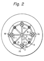
- sunbeam detectors 6 ⁇ 1, 6-1 and 6'-1, 6'-2 which are located at an equiangular distance of 90° and which will be discussed in detail hereinafter.
- the frames 3 which are diametrically arranged are connected to horizontal drive shafts 8 of first motors 7 which are are supported by a generally U-shaped arm 29, so that the assembly (the ring frame 15, the frames 3, the Fresnel lens 1) can rotate about a horizontal axis extending between the two shafts 8 when the motors 7 and, accordingly, the shafts 8, rotate.
- the motors 7 are driven by solar cells 5A, 5B and 5C. In the illustrated embodiments, three solar cells are advantageously provided, but the number of the solar cells is not limited to three and may be one, two or more than three.
- the solar cell 5A which may be of a ring-shape, is secured to a cylindrical support 28 which is connected and surrounds the Fresnel lens 1.
- the solar cells 5B and 5C which may be of a ring-shape and of a disc-shape, respectively, are connected to and supported by the frames 3.
- the solar cells are all located out of the imaginary core formed by the frames 3, so that the cells are not directly exposed to the sunbeams collected by the Fresnel lens 1.
- the sunbeams collected by the Fresnel lens 1 run along and are located within the imaginary cone.
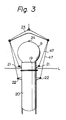
- the spherical capsule 9 is supported by a cylindrical support 19. Since, in the illustrated embodiment, the apparatus is intended to be floated on the sea, the cylindrical support 19 is rigidly connected to a cylindrical buoy 20 by means of bolts 26. Between the cylindrical support 19 and the buoy 20 is arranged an upper disc plate 25 which has a center hole 25a in which a vertical and hollow rotating shaft 10 is rotatably supported by means of a bearing 11. The upper disc plate 25 provides a sealed chamber 50 in the capsule 9.
- the rotating shaft 10 is rigidly connected to the arm 29 so that the arm 29 can rotate together with the shaft 10.
- the cable 4 extends through the shaft 10.
- the shaft 10 has a gear 53 which is rigidly connected thereto and which is engaged by a drive gear 52 in a gear box 51.
- the gear 52 is connected to a vertical drive shaft 12A of a second motor 12 located on the gear box 51 to transmit the rotation of the second motor 12 to the rotating shaft 10.
- the gear box 51 is supported on a lower disc plate 55 connected to the buoy 20.
- the numeral 11 designates a bearing for rotatably supporting the shaft 10.
- a storage battery 13 to which the solar cells 5A, 5B and 5C are electrically connected.
- the battery 13 is also electrically connected to the motors 7 and 12.
- the solar cells can be directly connected to the motors 7 and 12 to drive the motors.
- the detectors 6-1, 6-2 and 6'-1, 6'-2 such as photosensors located on the annular frame 15, have inclined sunbeam receiving surfaces 6A-1, 6A-2 and 6A'-1, 6A'-2, respectively.
- the inclined surfaces 6A-1, 6A-2 and 6A'-1, 6A'-2 are substantially flush with a generatrix of the imaginary cone defined by the sunbeams collected by the Fresnel lens 1, so that when the Fresnel lens 1 is directed to and exactly oppposed the sun, the inclined surfaces of the detectors 6-1, 6-2 and 6'-1, 6'-2 do not receive the sunbeams designated by arrows S.
- the detectors 6-1, 6-2 and 6'-1, 6'-2 issue detecting signals only when the respective inclined surfaces receive sunbeams, i.e. only when the Fresnel lens 1 is deviated from the position of the sun.
- the detectors are electrically connected to a controller 14.
- the controller 14 controls the operation of the motors 7 and 12 in accordance with the detecting signals from the respective detectors 6-1, 6-2 and 6'-1, 6'-2.
- the center axis X-X of the apparatus is parallel to sunbeams S, direct sunbeams do not arrive at the inclined surfaces 6a nor 6a' of the sunbeam detectors and outputs of these sunbeam detectors respond only to indirect spacious rays.
- the apparatus is inclined at an angle 8 1 to the incident direction, direct sunbeams arrive only at the beam detector 6-2.
- the apparatus can be always directed to the sun, that is, the optical axis X-X of the apparatus is parallel to the sunbeams.
- the axes of the shafts 8 and the shaft 10 intersect with each other generally at the center of the spherical capsule 9.
- the elements arranged in the capsule 9 are all balanced with respect to the center of the spherical capsule 9, so that no eccentric load is applied to the horizontal shafts 8 and the vertical shaft 10, thus resulting in a decrease of the drive power of the motors 7 and 12.
- an additional sunbeam detector 70 (Fig. 1) is provided on the upper surface of the Fresnel lens 1, so that the detector 70 almost always receives the sunbeams from sunset till sunrise.
- the additional detector 70 is adapted to- ensure the tracking movement of the apparatus, even when the sunbeams are weak, particularly at about sunset or on a cloudy day.
- the sunbeams are weak, the difference between the outputs of the detectors 6-1 and 6 ⁇ 2 or 6'-1 and 6'-2 becomes small, which may cause the apparatus to fail to follow the sun.
- the apparatus is designed in such a way that if follows the sun, even when the controller 14 detects a very small difference between the output of the pairs of detectors 6-1, 6-2 and 6'1, 6'2, the displacement of the apparatus for tracking the sun tends to become too large under strong sunbeams during daytime.
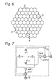
- the difference of the outputs between the detectors 6-1, 6 ⁇ 2 and 6'-1, 6'-2 can be divided by the output of additional detector 70, by means of dividers DIV1 and DIV2 (Fig. 7). That is, supposing that L 1 , L 2 and L o designate the output of the detectors 6-1 (or 6'-1 6-2 (or 6'-2) and 70, respectively, the DIV1 and DIV2 operates;
- the differences (L,-L 2 ) of the outputs between the detectors 6-1 and 6-2 (6'-1 and 6'-2), during the daytime is larger than that at about sunset
- the output (L o ) of the additional detector 70 during the daytime is also larger than that at about sunset.
- the output of the detector 70 can be considered a variable reference which varies in accordance with the strength or amount of the sunbeams, for the divisional operation by the dividers DIV1 and DIV2.
- the motors 7 (and/or 12) are driven when the ratio is larger than a predetermined value ⁇ ;[(L 1 ⁇ L 2 )/L o ⁇ ].
- the capsule 9 protects all of the elements provided therein from the external influences, such as wind or rain, and from corrosive substances, such as salt water.
- the apparatus When the apparatus is floated on the sea (the sea level is designated by L in Fig. 3), the apparatus can be first hung by ropes 47 with the help of a hanger 23, for example, from a ship (not shown).
- the ropes 47 can be connected to eye members 21, 22 secured to the cylindrical support 19 and the buoy 20, respectively.
- the numeral 24 (Fig. 3) designates a warning lamp for indicating the presence of the apparatus on the sea.
- the elements are arranged in the protecting capsule, they are protected from the wind, which has a bad influence on the movement of the apparatus, as well as from dust or undesirable chemical substances which pollute or corrode the elements.
- the inside of the capsule is sealed, and the temperature in the capsule can be easily controlled to prevent moisture from condensing on the inner wall of the capsule.
- the apparatus when the apparatus is floated on the sea, the apparatus may swing or oscillate under the the influence of the waves.
- the apparatus when the apparatus swings in the directions A (Fig. 1), a quick response to the swing movement cannot be expected, because the motor 12 first drives to rotate the Fresnel lens 1 about the shaft 10 and then the motors 7 drive to rotate the Fresnel lens 1 about the shafts 8.
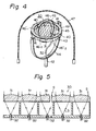
- a gimbal ring mechanism can be provided, as shown in Fig. 4.
- a thin lens means 30 which, for example, comprises a plurality of small diameter lenses 31 having a short focal length (Fig. 5).
- the lens means 30 is supported by a second gimbal ring 49 which is rotatably supported by a second gimbal ring 43 by means of first horizontal rotating shafts 40.
- the second gimbal ring 43 is rotatably supported by a generally U-shaped gimbal arm 44 by means of second horizontal rotating shafts 41 which extend perpendicular to the first rotating shafts 40 in the same plane.
- the gimbal arm 44 is connected to a vertical rotating shaft 42 which corresponds to the vertical rotating shaft 10 in Fig. 1.
- Two pairs of sunbeam detectors 46-1, 46-2 and 46'-1, 46'-2 are located on the first gimbal ring 49 at an equiangular distance of 90°.
- the first horizontal rotating shafts 40 and vertical shaft 42 are driven by respective motors (not shown), corresponding to the motor 12 in Fig. 1, in such a way that the difference between the outputs of the detectors 46-1 and 46-2 becomes zero.
- the second horizontal shafts 41 are driven by a motor (not shown) corresponding to the motors 7 in Fig. 1, in such a way that the differences between the outputs of the detectors 46'-1 and 46'-2 is zero.
- the detectors may be small pieces of optical sensors.
- the numeral 47 designates a transparent capsule, corresponding to the spherical capsule 9 in Fig. 1, but consisting of a semispherical portion and a cylindrical portion.
- Optical fibers 23 are provided, one for each small lens 31, as shown in Fig. 5, and are located at the focuses of the corresponding lenses 31. In Fig. 4, only one optical fiber 32 is shown.
- the fibers 32 preferably extend together in the shaft 42. Since, the lens means 30 is composed of a plurality of small lenses 31, the focal length of the lens means can be decreased, in comparison with that of the lens means 1 in Fig. 1.
- a single Fresnel lens on the market having a diameter of 35 cm can be used.
- the single Fresnel lens of 35 cm can be replaced by sixty one small lenses 31 each having a diameter of 4 cm, in the same area as that of the single Fresnel lens.
- the largest number of the small lenses 31 can be obtained when the small lenses are regular hexagons in a honeycomb arrangement, as shown in Fig. 6.
- the lens means 30, consisting of the sixty one small lenses 31 of 4 cm in diameter, has a focal length of about 4.5 cm, whereas the focal length of the lens means consisting of a single Fresnel lens of 35 cm diameter is approximately 39 cm.
- a ring shape solar cell 45 can be provided on the first gimbal ring 49 and/or the second gimbal ring 43. Alternatively, it is also possible to replace some of the small lenses 31 by solar cells.
- the lens means can quickly follow the sun by moving in all directions and, accordingly, the apparatus can easily adjust to the direction of the lens means, even under the adverse influence of waves.
- an apparatus for collecting and concentrating solar light energy which can easily follow the seasonal, daily and hourly “movement” of the sun and which can easily and quickly adjust to the direction of the lens means, which tends to fluctuate due to waves when the apparatus is floated on the sea.
Landscapes
- Engineering & Computer Science (AREA)
- Physics & Mathematics (AREA)
- Life Sciences & Earth Sciences (AREA)
- Sustainable Development (AREA)
- Electromagnetism (AREA)
- General Physics & Mathematics (AREA)
- Chemical & Material Sciences (AREA)
- Combustion & Propulsion (AREA)
- Mechanical Engineering (AREA)
- General Engineering & Computer Science (AREA)
- Sustainable Energy (AREA)
- Thermal Sciences (AREA)
- Condensed Matter Physics & Semiconductors (AREA)
- Computer Hardware Design (AREA)
- Microelectronics & Electronic Packaging (AREA)
- Power Engineering (AREA)
- Radar, Positioning & Navigation (AREA)
- Remote Sensing (AREA)
- Photovoltaic Devices (AREA)
- Mounting And Adjusting Of Optical Elements (AREA)
Claims (16)
Applications Claiming Priority (4)
| Application Number | Priority Date | Filing Date | Title |
|---|---|---|---|
| JP9246880A JPS5717182A (en) | 1980-07-07 | 1980-07-07 | Collector for solar ray energy |
| JP92468/80 | 1980-07-07 | ||
| JP66942/81 | 1981-05-06 | ||
| JP56066942A JPS57182708A (en) | 1981-05-06 | 1981-05-06 | Gathering device for solar light energy |
Publications (3)
| Publication Number | Publication Date |
|---|---|
| EP0050189A2 EP0050189A2 (fr) | 1982-04-28 |
| EP0050189A3 EP0050189A3 (en) | 1982-11-10 |
| EP0050189B1 true EP0050189B1 (fr) | 1986-11-05 |
Family
ID=26408144
Family Applications (1)
| Application Number | Title | Priority Date | Filing Date |
|---|---|---|---|
| EP81105119A Expired EP0050189B1 (fr) | 1980-07-07 | 1981-07-02 | Appareil pour collectionner et concentrer l'énergie de la lumière solaire |
Country Status (5)
| Country | Link |
|---|---|
| US (1) | US4447718A (fr) |
| EP (1) | EP0050189B1 (fr) |
| DE (1) | DE3175573D1 (fr) |
| HK (1) | HK96387A (fr) |
| SG (1) | SG60487G (fr) |
Families Citing this family (19)
| Publication number | Priority date | Publication date | Assignee | Title |
|---|---|---|---|---|
| AU557732B2 (en) * | 1981-05-09 | 1987-01-08 | Mori, K. | Sunlight direction sensor |
| JPS5813961A (ja) * | 1981-07-18 | 1983-01-26 | Takashi Mori | 太陽光収集装置 |
| US4511755A (en) * | 1982-05-17 | 1985-04-16 | Kei Mori | Solar ray collection apparatus |
| JPS59124308A (ja) * | 1982-12-31 | 1984-07-18 | Takashi Mori | 光導体の受光端をレンズの焦点位置に合わせるための構造及びそのための器具 |
| JPS59224804A (ja) * | 1983-06-03 | 1984-12-17 | Takashi Mori | 太陽光収集装置 |
| JPS6064315A (ja) * | 1983-09-19 | 1985-04-12 | Takashi Mori | 太陽光収集装置 |
| JPS6078403A (ja) * | 1983-10-04 | 1985-05-04 | Takashi Mori | 宇宙空間用太陽光収集装置 |
| JPS61119125A (ja) * | 1984-11-15 | 1986-06-06 | 森 敬 | 養魚装置 |
| US4710618A (en) * | 1986-01-29 | 1987-12-01 | The United States Of America As Represented By The Administrator Of The National Aeronautics And Space Administration | Airborne tracking sunphotometer apparatus and system |
| JPS63310010A (ja) * | 1987-06-11 | 1988-12-19 | Mitsubishi Rayon Co Ltd | 太陽光追尾装置 |
| DE3736616C1 (de) * | 1987-10-29 | 1989-02-09 | Messerschmitt Boelkow Blohm | Optischer Weitwinkel-Sensorkopf |
| CZ283818B6 (cs) * | 1996-12-12 | 1998-06-17 | Vladislav Ing. Csc. Poulek | Zařízení pro orientaci kolektorů sluneční energie |
| WO2008096019A1 (fr) | 2007-02-09 | 2008-08-14 | Ingeteam Energy, S.A. | Dispositif de conversion de courant continu en courant alternatif et de commande de puissance maximale pour des panneaux solaires |
| NL1034015C2 (nl) * | 2007-06-22 | 2008-12-23 | Schilder Johannes Jacobus Mari | Zonnecollector met lensmiddelen. |
| GB2469344B (en) * | 2009-07-23 | 2011-08-24 | Iain Chapman | Moveable mounting |
| CN104904611B (zh) * | 2015-05-20 | 2017-05-17 | 江苏曜曜机械科技有限公司 | 一种树形可旋转养殖支架 |
| US10267538B2 (en) * | 2016-09-15 | 2019-04-23 | Rodluvan Inc. | Method for conveying concentrated solar power |
| US10557647B2 (en) * | 2016-09-15 | 2020-02-11 | Rodluven Inc. | Method for conveying concentrated solar power |
| US10234173B2 (en) * | 2016-09-15 | 2019-03-19 | Rodluvan Inc. | Method for conveying concentrated solar power |
Family Cites Families (10)
| Publication number | Priority date | Publication date | Assignee | Title |
|---|---|---|---|---|
| DE1299164B (de) * | 1965-05-25 | 1969-07-10 | Busch | Anlage zur kontinuierlichen Algengewinnung |
| DE2358701C3 (de) * | 1973-11-24 | 1981-01-22 | Erno Raumfahrttechnik Gmbh, 2800 Bremen | Vorrichtung zur Aufzucht von Algen |
| FR2310477A1 (fr) * | 1975-05-09 | 1976-12-03 | Comp Generale Electricite | Dispositif generateur electrique par concentration de l'energie solaire |
| FR2384216A1 (en) * | 1976-12-03 | 1978-10-13 | Seyve Daniel | Solar heater including magnifying glass concentrating radiation - on end of rotating bent optical fibre, giving large heat-exchange surface coverage by transmitted radiation |
| US4223214A (en) * | 1978-01-09 | 1980-09-16 | American Solar Systems, Inc. | Solar tracking device |
| US4201197A (en) * | 1978-03-20 | 1980-05-06 | Dismer Raymond H | Solar energy collector having a fiber-optic cable |
| DE2834827A1 (de) * | 1978-08-09 | 1980-02-14 | Maschf Augsburg Nuernberg Ag | Solarspiegelanlage |
| US4225781A (en) * | 1979-02-26 | 1980-09-30 | The United States Of America As Represented By The United States Department Of Energy | Solar tracking apparatus |
| US4340812A (en) * | 1979-03-26 | 1982-07-20 | Kei Mori | Radiation energy collection and tracking apparatus |
| DE3164874D1 (en) * | 1980-06-27 | 1984-08-23 | Kei Mori | A solar optical energy collector |
-
1981
- 1981-06-29 US US06/278,202 patent/US4447718A/en not_active Expired - Fee Related
- 1981-07-02 DE DE8181105119T patent/DE3175573D1/de not_active Expired
- 1981-07-02 EP EP81105119A patent/EP0050189B1/fr not_active Expired
-
1987
- 1987-07-24 SG SG604/87A patent/SG60487G/en unknown
- 1987-12-17 HK HK963/87A patent/HK96387A/xx unknown
Also Published As
| Publication number | Publication date |
|---|---|
| EP0050189A3 (en) | 1982-11-10 |
| HK96387A (en) | 1987-12-24 |
| US4447718A (en) | 1984-05-08 |
| SG60487G (en) | 1987-10-23 |
| EP0050189A2 (fr) | 1982-04-28 |
| DE3175573D1 (en) | 1986-12-11 |
Similar Documents
| Publication | Publication Date | Title |
|---|---|---|
| EP0050189B1 (fr) | Appareil pour collectionner et concentrer l'énergie de la lumière solaire | |
| US7642450B2 (en) | Collector for solar radiation | |
| EP0155666B1 (fr) | Mécanisme de poursuite solaire | |
| AU2005281843B2 (en) | Floating solar platform | |
| AU2002337841B2 (en) | Method and apparatus for solar energy collection | |
| KR910008215B1 (ko) | 해수중의 생물 육성 장치 | |
| CN1568550A (zh) | 太阳能发电装置 | |
| US20080257398A1 (en) | Floating Solar Platform | |
| CN102374477A (zh) | 一种阳光智能入户系统 | |
| NZ198834A (en) | Sunbeam tracking,concentrating and guiding apparatus in transparent capsule | |
| US4339626A (en) | Solar pond power plant | |
| EP0043082B1 (fr) | Collecteur d'énergie solaire optique | |
| JP3769556B2 (ja) | 水上太陽光発電装置 | |
| KR101298633B1 (ko) | 수상 플로트식 태양광 발전장치 | |
| JP6867771B2 (ja) | 固定的に取り付けられた追跡用ソーラーパネル及び方法 | |
| KR101358392B1 (ko) | 3줄의 와이어를 이용한 판상 부재의 구동 방법 및 장치와, 이를 이용한 태양 추적장치 및 태양광 반사장치 | |
| JPS61223909A (ja) | 太陽光追尾装置 | |
| KR20150051352A (ko) | 수상 태양광 추적장치 | |
| KR20170030844A (ko) | 수면부상식 태양광 발전장치 | |
| CN101308879B (zh) | 均质杆 | |
| KR200405781Y1 (ko) | 태양광 추적식 에너지발전장치 | |
| CN210624976U (zh) | 一种感光装置、太阳能集热装置及沼气系统 | |
| KR20210156958A (ko) | 반사경을 이용한 양면 태양광 모듈의 발전장치 | |
| KR101767870B1 (ko) | 태양 추적기능을 갖는 태양광 파라솔 | |
| JPH0449686Y2 (fr) |
Legal Events
| Date | Code | Title | Description |
|---|---|---|---|
| PUAI | Public reference made under article 153(3) epc to a published international application that has entered the european phase |
Free format text: ORIGINAL CODE: 0009012 |
|
| AK | Designated contracting states |
Designated state(s): DE FR GB IT SE |
|
| PUAL | Search report despatched |
Free format text: ORIGINAL CODE: 0009013 |
|
| 17P | Request for examination filed |
Effective date: 19820721 |
|
| AK | Designated contracting states |
Designated state(s): DE FR GB IT SE |
|
| 17Q | First examination report despatched |
Effective date: 19850503 |
|
| GRAA | (expected) grant |
Free format text: ORIGINAL CODE: 0009210 |
|
| AK | Designated contracting states |
Kind code of ref document: B1 Designated state(s): DE FR GB IT SE |
|
| ITF | It: translation for a ep patent filed |
Owner name: JACOBACCI & PERANI S.P.A. |
|
| REF | Corresponds to: |
Ref document number: 3175573 Country of ref document: DE Date of ref document: 19861211 |
|
| ET | Fr: translation filed | ||
| PLBE | No opposition filed within time limit |
Free format text: ORIGINAL CODE: 0009261 |
|
| STAA | Information on the status of an ep patent application or granted ep patent |
Free format text: STATUS: NO OPPOSITION FILED WITHIN TIME LIMIT |
|
| 26N | No opposition filed | ||
| PGFP | Annual fee paid to national office [announced via postgrant information from national office to epo] |
Ref country code: SE Payment date: 19890606 Year of fee payment: 9 |
|
| PGFP | Annual fee paid to national office [announced via postgrant information from national office to epo] |
Ref country code: GB Payment date: 19890630 Year of fee payment: 9 |
|
| ITTA | It: last paid annual fee | ||
| PG25 | Lapsed in a contracting state [announced via postgrant information from national office to epo] |
Ref country code: GB Effective date: 19900702 |
|
| PG25 | Lapsed in a contracting state [announced via postgrant information from national office to epo] |
Ref country code: SE Effective date: 19900703 |
|
| PGFP | Annual fee paid to national office [announced via postgrant information from national office to epo] |
Ref country code: FR Payment date: 19900730 Year of fee payment: 10 |
|
| PGFP | Annual fee paid to national office [announced via postgrant information from national office to epo] |
Ref country code: DE Payment date: 19900810 Year of fee payment: 10 |
|
| GBPC | Gb: european patent ceased through non-payment of renewal fee | ||
| PG25 | Lapsed in a contracting state [announced via postgrant information from national office to epo] |
Ref country code: FR Effective date: 19920331 |
|
| PG25 | Lapsed in a contracting state [announced via postgrant information from national office to epo] |
Ref country code: DE Effective date: 19920401 |
|
| REG | Reference to a national code |
Ref country code: FR Ref legal event code: ST |
|
| EUG | Se: european patent has lapsed |
Ref document number: 81105119.2 Effective date: 19910402 |