EP0048843B1 - Kontaktbuchse mit schraubenloser Anschlussklemme für elektrische Steckdosen - Google Patents
Kontaktbuchse mit schraubenloser Anschlussklemme für elektrische Steckdosen Download PDFInfo
- Publication number
- EP0048843B1 EP0048843B1 EP81107008A EP81107008A EP0048843B1 EP 0048843 B1 EP0048843 B1 EP 0048843B1 EP 81107008 A EP81107008 A EP 81107008A EP 81107008 A EP81107008 A EP 81107008A EP 0048843 B1 EP0048843 B1 EP 0048843B1
- Authority
- EP
- European Patent Office
- Prior art keywords
- extensions
- clamping
- contact
- clamping plate
- lateral walls
- Prior art date
- Legal status (The legal status is an assumption and is not a legal conclusion. Google has not performed a legal analysis and makes no representation as to the accuracy of the status listed.)
- Expired
Links
- 239000004020 conductor Substances 0.000 claims abstract description 28
- 238000003780 insertion Methods 0.000 claims abstract description 14
- 230000037431 insertion Effects 0.000 claims abstract description 14
- 210000002105 tongue Anatomy 0.000 claims abstract description 7
- 238000004519 manufacturing process Methods 0.000 description 3
- 230000002411 adverse Effects 0.000 description 1
- 238000013459 approach Methods 0.000 description 1
- 238000005452 bending Methods 0.000 description 1
- 239000002131 composite material Substances 0.000 description 1
- 238000010276 construction Methods 0.000 description 1
- 238000005520 cutting process Methods 0.000 description 1
- 238000001746 injection moulding Methods 0.000 description 1
- WABPQHHGFIMREM-UHFFFAOYSA-N lead(0) Chemical compound [Pb] WABPQHHGFIMREM-UHFFFAOYSA-N 0.000 description 1
- 238000000034 method Methods 0.000 description 1
- 230000000149 penetrating effect Effects 0.000 description 1
- 238000003825 pressing Methods 0.000 description 1
Images

Classifications
-
- H—ELECTRICITY
- H01—ELECTRIC ELEMENTS
- H01R—ELECTRICALLY-CONDUCTIVE CONNECTIONS; STRUCTURAL ASSOCIATIONS OF A PLURALITY OF MUTUALLY-INSULATED ELECTRICAL CONNECTING ELEMENTS; COUPLING DEVICES; CURRENT COLLECTORS
- H01R24/00—Two-part coupling devices, or either of their cooperating parts, characterised by their overall structure
- H01R24/76—Two-part coupling devices, or either of their cooperating parts, characterised by their overall structure with sockets, clips or analogous contacts and secured to apparatus or structure, e.g. to a wall
-
- H—ELECTRICITY
- H01—ELECTRIC ELEMENTS
- H01R—ELECTRICALLY-CONDUCTIVE CONNECTIONS; STRUCTURAL ASSOCIATIONS OF A PLURALITY OF MUTUALLY-INSULATED ELECTRICAL CONNECTING ELEMENTS; COUPLING DEVICES; CURRENT COLLECTORS
- H01R2103/00—Two poles
-
- H—ELECTRICITY
- H01—ELECTRIC ELEMENTS
- H01R—ELECTRICALLY-CONDUCTIVE CONNECTIONS; STRUCTURAL ASSOCIATIONS OF A PLURALITY OF MUTUALLY-INSULATED ELECTRICAL CONNECTING ELEMENTS; COUPLING DEVICES; CURRENT COLLECTORS
- H01R4/00—Electrically-conductive connections between two or more conductive members in direct contact, i.e. touching one another; Means for effecting or maintaining such contact; Electrically-conductive connections having two or more spaced connecting locations for conductors and using contact members penetrating insulation
- H01R4/28—Clamped connections, spring connections
- H01R4/48—Clamped connections, spring connections utilising a spring, clip, or other resilient member
Definitions
- the invention relates to a contact socket with a screwless connection terminal for electrical sockets, which is fastened in a contact carrier within a recess open to the front side thereof, the connection terminal consisting of a clamping plate and a clamping spring in the form of a two-leg leaf spring, the leaf spring being supported in a stationary manner with its support leg and is pressed with its clamping leg obliquely in the direction of insertion of a conductor against the clamping plate for fixing at least one conductor, with projections formed on the free end of the clamping leg and penetrating an opening in the clamping plate for the purpose of releasing a conductor, the clamping plate being connected to the parallel in The direction of insertion of the conductor extending longitudinal sides of the side walls are angled, between which the clamping spring is guided and which have extensions in the direction of insertion of the conductor, which form the plug contact socket at its free ends with semicircular Er Extensions are provided for receiving a plug pin, the side edge of the clamping plate lying between the extensions being
- the leaf spring of the screwless connecting terminal is arranged below the clamping plate in the recess of the contact carrier in such a way that it must first be inserted into this recess and locked in a position-securing manner on a special pin of the contact carrier, while doing so its clamping leg with its front Bug comes to rest behind a web of the contact carrier.
- the contact socket is then inserted into the recess, care being taken that the extensions of the clamping spring thread into the window-like opening in the clamping plate (DE-U-1989058).
- the actual plug contact socket is designed so that it is provided with a special wire spring to achieve sufficient contact pressure forces.
- a retaining tab is formed for fastening the contact socket to the contact carrier of the wall delimiting the insertion of the conductor.
- This contact socket is still relatively expensive to manufacture and to build, and its assembly is extremely difficult due to the large number of individual parts and the special design and mounting of the clamping spring.
- the support of the clamping spring on the contact carrier means that there is no non-positive connection to the clamping plate, which in practice jeopardizes the secure clamping of the lead wires.
- by holding the contact socket by means of the wall delimiting the insertion of the conductors, there is the risk that the clamping plate can be easily bent under the transverse forces acting on the connected conductors, so that a reliable line connection is no longer provided.
- the object of the invention is to provide a contact socket with a screwless terminal, which is easy to manufacture by rational construction of the individual parts and easy to assemble.
- the contact socket with the clamping plate should be able to be produced very cheaply in a composite tool and the contact carrier should be produced in a pressing or injection molding tool in the normal counterpressing process without a sideshift.
- there should be the possibility of being able to assemble the contact socket with the clamping spring by mechanical assembly as an assembly and it should also be possible to insert this assembly into the recesses of the contact carrier in an automatic manufacturing process and to reliably fix it mechanically to the contact carrier.
- the clamping spring should be held non-positively on the clamping plate and, after fastening the contact socket with a connecting terminal to the contact carrier, the clamping force should remain properly ensured by loads on the lead wire even when transverse forces occur.
- the side walls are formed with projecting lugs, behind which the support leg of the clamping spring engages and is held non-positively, that the side walls penetrate openings of the contact carrier by means of molded tongues and are held on the contact carrier by folding their ends over and that the contact socket-forming extensions are bent by 180 ° with their semicircular extensions.
- a further embodiment of the invention consists in the fact that the supporting leg of the clamping spring engages around the tongues of the side walls by means of lateral approaches.
- the contact socket according to the invention is shown in the drawing using an exemplary embodiment.
- the contact socket 3 consists first of all of a clamping plate 4 with side walls 5 angled on parallel longitudinal sides, which with Extensions 6 extending beyond the length of the clamping plate 4 are provided, the ends of which have semicircular extensions 7 for receiving a plug pin.
- the semicircular extensions 7 are bent inwards by 180 ° and thereby form a reliable plug contact socket.
- the side walls 5 are molded inwardly projecting lugs 8.
- a designed as a leaf spring and approximately V-shaped curved spring 9 is supported with its support leg 10 on the lugs 8 and is inclined with the free end of its clamping leg 11 obliquely in the direction of insertion of a conductor 18 against the clamping plate 4, where an inserted conductor 18 is a hook-shaped hold on and contact.
- An extension 12 is formed on the free end of the clamping leg 11 and penetrates a window-like opening 13 ′ in the clamping plate 4 and can be actuated by hand or by means of a tool for releasing a conductor 18.
- the clamping leg 11 is slotted in the middle, as a result of which two separate clamping legs 11 are formed for clamping two conductors 18.
- a wall 17 is angled through which the insertion of the conductor 18 is limited.
- Tongues 14 are formed on the side walls 5, penetrate the openings 15 in the contact carrier 1 and, by bending their ends 16, reliably hold the terminal on the contact carrier 1.
- This type of attachment to the contact carrier ensures reliable clamping of the conductors 18 in the screwless connecting terminal, since no adverse influence on the clamping force of the clamping spring 9 is possible even with transverse forces acting on the conductors 18.
- the clamping spring 9 has on its support leg 10 lateral lugs 19 which engage around the tongues 14 of the side walls 5.
Landscapes
- Connections Arranged To Contact A Plurality Of Conductors (AREA)
- Clamps And Clips (AREA)
- Details Of Connecting Devices For Male And Female Coupling (AREA)
- Connector Housings Or Holding Contact Members (AREA)
- Manufacturing Of Electrical Connectors (AREA)
- Heterocyclic Carbon Compounds Containing A Hetero Ring Having Oxygen Or Sulfur (AREA)
- Acyclic And Carbocyclic Compounds In Medicinal Compositions (AREA)
Description
- Die Erfindung betrifft eine Kontaktbuchse mit schraubenloser Anschlussklemme für elektrische Steckdosen, die in einem Kontaktträger innerhalb einer zu dessen Stirnseite offenen Ausnehmung befestigt ist, wobei die Anschlussklemme aus einer Klemmplatte und einer Klemmfeder in Form einer zweischenkligen Blattfeder besteht, wobei die Blattfeder mit ihrem Stützschenkel ortsfest abgestützt und mit ihrem Klemmschenkel schräg in Einsteckrichtung eines Leiters gegen die Klemmplatte zur Festlegung mindestens eines Leiters gedrückt ist, mit am freien Ende des Klemmschenkels angeformten Fortsätzen, die zum Zwecke des Lösens eines Leiters einen Durchbruch in der Klemmplatte durchdringen, wobei der Klemmplatte an den parallel in Einsteckrichtung der Leiter verlaufenden Längsseiten Seitenwände angewinkelt sind, zwischen denen die Klemmfeder geführt ist und die in Einsteckrichtung der Leiter Verlängerungen aufweisen, die zur Bildung der Steckkontaktbuchse an ihren freien Enden mit halbkreisförmigen Erweiterungen zur Aufnahme eines Steckerstiftes versehen sind, wobei der zwischen den Verlängerungen liegenden Seitenkante der Klemmplatte eine Wand angewinkelt ist, durch die das Einführen der Leiter begrenzt ist und wobei die Kontaktbuchse im Bereich ihrer Anschlussklemme mittels Fortsätzen am Kontaktträger festgelegt ist.
- Bei einer Kontaktbuchse in der beschriebenen Art ist die Blattfeder der schraubenlosen Anschlussklemme unterhalb der Klemmplatte in der Ausnehmung des Kontaktträgers so angeordnet, dass sie zunächst in diese Ausnehmung eingesetzt und auf einen besonderen Zapfen des Kontaktträgers lagesichernd arretiert werden muss, während dabei ihr Klemmschenkel mit seinem vorderen Bug hinter einem Steg des Kontaktträgers zu liegen kommt.
- Anschliessend wird die Kontaktbuchse in die Ausnehmung eingesetzt, wobei darauf geachtet werden muss, dass sich die Fortsätze der Klemmfeder in den fensterartigen Durchbruch der Klemmplatte einfädeln (DE-U-1989058). Die eigentliche Steckkontaktbuchse ist dabei so ausgebildet, dass sie zur Erzielung ausreichender Kontaktdruckkräfte mit einer besonderen Drahtfeder versehen ist. Für eine Befestigung der Kontaktbuchse an dem Kontaktträger der die Einführung des Leiters begrenzenden Wand ein Haltelappen angeformt. Diese Kontaktbuchse ist in ihrer Herstellung und in ihrem Aufbau noch relativ aufwendig und ihre Montage durch die Vielzahl der Einzelteile sowie durch die besondere Ausbildung und Halterung der Klemmfeder äusserst schwierig. Darüberhinaus ist durch die Abstützung der Klemmfeder an dem Kontaktträger keine kraftschlüssige Verbindung mit der Klemmplatte gegeben, wodurch in der Praxis eine sichere Klemmung der Leitungsdrähte in Frage gestellt ist. Ausserdem besteht durch die Halterung der Kontaktbuchse mittels der das Einführen der Leiter begrenzenden Wand die Gefahr, dass bei auf den angeschlossenen Leiter einwirkenden Querkräften die Klemmplatte leicht abgebogen werden kann, so dass auch hierdurch ein zuverlässiger Leitungsanschluss nicht mehr gegeben ist.
- Aufgabe der Erfindung ist es, eine Kontaktbuchse mit schraubenloser Anschlussklemme zu schaffen, die leicht herstellbar durch rationellen Aufbau der Einzelteile und montagefreundlich ausgebildet ist. Dabei soll die Kontaktbuchse mit der Klemmplatte in einem Verbundwerkzeug sehr günstig herstellbar sein und die Herstellung des Kontaktträgers in einem Press- oder Spritzwerkzeug im normalen Gegenpressverfahren ohne Seitenschieber gegeben sein. Ausserdem soll die Möglichkeit bestehen, die Kontaktbuchse mit der Klemmfeder durch maschinelle Montage als Baugruppe zusammenfügen zu können und soll es ebenso möglich sein, diese Baugruppe in einem automatischen Fertigungsverfahren in die Ausnehmungen des Kontaktträgers einzubringen und sie zuverlässig auf maschinelle Weise an dem Kontaktträger zu befestigen. Hierbei soll die Klemmfeder kraftschlüssig an der Klemmplatte gehalten sein und nach Befestigung der Kontaktbuchse mit Anschlussklemme an dem Kontaktträger soll die Klemmkraft durch Belastungen des Leitungsdrahtes auch bei auftretenden Querkräften einwandfrei sichergestellt bleiben.
- Erfindungsgemäss wird dies dadurch gelöst, dass den Seitenwänden nach innen vorspringende Nasen angeformt sind, hinter die der Stützschenkel der Klemmfeder einrastet und kraftschlüssig gehalten ist, dass die Seitenwände mittels angeformter Zungen Durchbrüche des Kontaktträgers durchdringen und durch Umlegen ihrer Enden am Kontaktträger gehalten sind und dass die die Kontaktbuchse bildenden Verlängerungen mit ihren halbkreisförmigen Erweiterungen um 180° umgebogen sind.
- Eine weitere Ausgestaltung der Erfindung besteht darin, dass der Stützschenkel der Klemmfeder mittels seitlicher Ansätze die Zungen der Seitenwände umgreift.
- Die Kontaktbuchse nach der Erfindung ist in der Zeichnung an einem Ausführungsbeispiel dargestellt.
- Es zeigen:
- Fig. 1 eine Draufsicht eines Kontaktträgers mit in diesem befestigten Kontaktbuchsen,
- Fig. 2 einen Längsschnitt durch Kontaktbuchse und Kontaktträger gem. Schnittlinie 11-11,
- Fig. 3 einen Querschnitt durch die Befestigung der Kontaktbuchse an dem Kontaktträger gem. Schnittlinie 111-111.
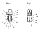
- Fig. 4 einen Längsschnitt durch die Kontaktbuchse und
- Fig. 5 eine Unteransicht der Kontaktbuchse.
- In dem Kontaktträger 1 befinden sich Ausnehmungen 2, die zur Stirnseite des Kontaktträgers für die Aufnahme von Kontaktbuchsen 3 völlig offen sind. Die Kontaktbuchse 3 besteht zunächst aus einer Klemmplatte 4 mit an parallelen Längsseiten angewinkelten Seitenwänden 5, die mit über die Länge der Klemmplatte 4 hinausgehende Verlängerungen 6 versehen sind, deren Enden halbkreisförmige Erweiterungen 7 aufweisen, für die Aufnahme eines Steckerstiftes. Die halbkreisförmigen Erweiterungen 7 sind um 180° nach innen umgebogen und bilden dadurch eine zuverlässige Steckkontaktbuchse. Den Seitenwänden 5 sind nach innen vorspringende Nasen 8 angeformt. Eine als Blattfeder ausgebildete und etwa V-förmig gebogene Klemmfeder 9 stützt sich mit ihrem Stützschenkel 10 auf den Nasen 8 ab und liegt mit dem freien Ende ihres Klemmschenkels 11 schräg in Einsteckrichtung eines Leiters 18 gegen die Klemmplatte 4, wo diese einen eingeführten Leiter 18 sperrhakenförmig festhalten und kontaktieren kann. An dem freien Ende des Klemmschenkels 11 ist ein Fortsatz 12 angeformt, der einen fensterartigen Durchbruch 13'in-der Klemmplatte 4 durchdringt und von Hand oder mittels eines Werkzeuges zum Lösen eines Leiters 18 betätigt werden kann. In dem dargestellten Beispiel ist der Klemmschenkel 11 in der Mitte geschlitzt, wodurch zwei getrennte Klemmschenkel 11 für die Klemmung von zwei Leiter 18 gebildet sind. An der Seitenkante der Klemmplatte 4, die zwischen den Verlängerungen 6 liegt, ist eine Wand 17 angewinkelt, durch die das Einführen der Leiter 18 begrenzt wird.
- Den Seitenwänden 5 sind Zungen 14 angeformt, die Durchbrüche 15 im Kontaktträger 1 durchdringen und durch Umbiegen ihrer Enden 16 zuverlässig die Anschlussklemme an dem Kontaktträger 1 festhalten. Durch diese Art der Befestigung an dem Kontaktträger ist eine zuverlässige Klemmung der Leiter 18 in der schraubenlosen Anschlussklemme gewährleistet, da auch bei auf die Leiter 18 einwirkenden Querkräften keine nachteilige Beeinflussung der Klemmkraft der Klemmfeder 9 möglich ist.
- Die Klemmfeder 9 besitzt an seinem Stützschenkel 10 seitliche Ansätze 19, die die Zungen 14 der Seitenwände 5 umgreifen.
- Hierdurch ist die Klemmfeder 9 an der Klemmplatte 4 gegen unbeabsichtigtes Lösen sicher gehalten.
- Durch die erfindungsgemässe Ausbildung ist ein leichtes maschinelles Zusammenfügen der Kontaktbuchse 3 mit der Klemmfeder 9 möglich, in dem diese von unten zwischen die Seitenwände 5 einschiebbar ist, bis zur Verrastung seines Stützschenkels 10 hinter die Nasen 8 und Auflage der seitlichen Ansätze 19 auf der Unterseite der Seitenwände 5.
Claims (2)
Priority Applications (1)
| Application Number | Priority Date | Filing Date | Title |
|---|---|---|---|
| AT81107008T ATE6559T1 (de) | 1980-09-24 | 1981-09-07 | Kontaktbuchse mit schraubenloser anschlussklemme fuer elektrische steckdosen. |
Applications Claiming Priority (2)
| Application Number | Priority Date | Filing Date | Title |
|---|---|---|---|
| DE3035886 | 1980-09-24 | ||
| DE19803035886 DE3035886A1 (de) | 1980-09-24 | 1980-09-24 | Kontaktbuchse mit schraubenloser anschlussklemme fuer elektrische steckdosen |
Publications (2)
| Publication Number | Publication Date |
|---|---|
| EP0048843A1 EP0048843A1 (de) | 1982-04-07 |
| EP0048843B1 true EP0048843B1 (de) | 1984-03-07 |
Family
ID=6112674
Family Applications (1)
| Application Number | Title | Priority Date | Filing Date |
|---|---|---|---|
| EP81107008A Expired EP0048843B1 (de) | 1980-09-24 | 1981-09-07 | Kontaktbuchse mit schraubenloser Anschlussklemme für elektrische Steckdosen |
Country Status (7)
| Country | Link |
|---|---|
| EP (1) | EP0048843B1 (de) |
| AT (1) | ATE6559T1 (de) |
| DE (1) | DE3035886A1 (de) |
| ES (1) | ES260437Y (de) |
| FI (1) | FI68741C (de) |
| NO (1) | NO158199C (de) |
| ZA (1) | ZA815681B (de) |
Families Citing this family (5)
| Publication number | Priority date | Publication date | Assignee | Title |
|---|---|---|---|---|
| GB8721302D0 (en) * | 1987-09-10 | 1987-10-14 | London King S College | Substrates for assay of enzymes |
| DE3809843A1 (de) * | 1988-03-24 | 1989-10-05 | Hochkoepper Paul Gmbh | Elektrische steckdose |
| DE9307141U1 (de) * | 1993-05-11 | 1993-07-15 | LT - Licht Technik GmbH, 4836 Herzebrock-Clarholz | Lichtleisten-Leuchte |
| DE20117770U1 (de) * | 2001-04-23 | 2002-09-05 | Weidmüller Interface GmbH & Co., 32760 Detmold | Federklemme |
| EP1253670B1 (de) | 2001-04-23 | 2006-04-26 | Weidmüller Interface GmbH & Co. | Federklemme und Federklemmenreihung |
Family Cites Families (3)
| Publication number | Priority date | Publication date | Assignee | Title |
|---|---|---|---|---|
| DE1615727A1 (de) * | 1967-04-06 | 1971-02-04 | Bbc Brown Boveri & Cie | Klemme zum schraubenlosen Anschluss von einem elektrischen Leitungsdraht bei Steckdosen |
| DE1615744A1 (de) * | 1967-05-12 | 1971-06-16 | Bbc Brown Boveri & Cie | Zweipolige elektrische Schutzkontakt-Steckdose |
| DE1989058U (de) * | 1968-04-20 | 1968-07-11 | Bayerische Elektrozubehoer G M | Anschlussklemme fuer steckdosen. |
-
1980
- 1980-09-24 DE DE19803035886 patent/DE3035886A1/de active Granted
-
1981
- 1981-08-18 ZA ZA815681A patent/ZA815681B/xx unknown
- 1981-09-07 AT AT81107008T patent/ATE6559T1/de not_active IP Right Cessation
- 1981-09-07 EP EP81107008A patent/EP0048843B1/de not_active Expired
- 1981-09-23 ES ES1981260437U patent/ES260437Y/es not_active Expired
- 1981-09-23 FI FI812970A patent/FI68741C/fi not_active IP Right Cessation
- 1981-09-23 NO NO813240A patent/NO158199C/no unknown
Also Published As
| Publication number | Publication date |
|---|---|
| NO158199C (no) | 1988-07-27 |
| ES260437U (es) | 1982-03-16 |
| ZA815681B (en) | 1982-08-25 |
| FI68741C (fi) | 1985-10-10 |
| DE3035886C2 (de) | 1988-09-01 |
| NO813240L (no) | 1982-03-25 |
| NO158199B (no) | 1988-04-18 |
| DE3035886A1 (de) | 1982-05-06 |
| EP0048843A1 (de) | 1982-04-07 |
| ES260437Y (es) | 1983-03-01 |
| FI68741B (fi) | 1985-06-28 |
| FI812970L (fi) | 1982-03-25 |
| ATE6559T1 (de) | 1984-03-15 |
Similar Documents
| Publication | Publication Date | Title |
|---|---|---|
| DE69427767T2 (de) | Elektrische Verbinder zum Kuppeln von zwei gedruckten Leiterplatten | |
| DE69702142T2 (de) | Elektrischer verbinder mit einem gehäuse und einem elektrischen kontaktelement | |
| DE4206987C2 (de) | Telefonbuchse | |
| DE2553558B2 (de) | ||
| DE8800759U1 (de) | Elektrischer Verbinder mit beweglichem Führungselement | |
| DE1540642A1 (de) | Elektrische Verbindungsklemme | |
| DE20117652U1 (de) | Verbindungseinheit für elektrische Leiter | |
| DE2454345A1 (de) | Einsteckgehaeuse fuer ein kontaktglied | |
| DE102006010163B4 (de) | Elektrisches Steckverbinderelement für Leiter mit gecrimpten Kontakten | |
| DE2309138A1 (de) | Elektrischer verbinder | |
| EP0213312A2 (de) | Anordnung zum Verbinden von in Buchsen- oder Steckergehäusen angeordneten Buchsen- oder Stiftkontakten mit Anschlussdrähten | |
| DE7303044U (de) | AnschluBkasten | |
| EP0584506B1 (de) | Elektrische Anschlussklemmleiste | |
| DE3637008C2 (de) | ||
| DE3035886C2 (de) | ||
| DE4230333A1 (de) | Metallklemmen-dualverriegelungsverbinder | |
| DE4446807C2 (de) | Steckverbindergehäuse | |
| DE2326543C3 (de) | Halterung für einen Leitungsstecker | |
| DE3939967A1 (de) | Zugentlastungsvorrichtung fuer elektrische leiter | |
| DE69804229T2 (de) | Verbinder mit kontaktlagefixierungsbauteil | |
| DE69206248T2 (de) | Anschlusselementsverriegelung für einen elektrischen Steckverbinder. | |
| DE2149987B2 (de) | Relaisfassung | |
| DE1615723C3 (de) | Elektrische Steckverbindung | |
| DE1665113C3 (de) | Elektrische Einrichtung, wie Stecker, Kupplung o.dgl | |
| DE2733220B2 (de) | Antennensteckdose mit einem topfförmigen Dosenkörper |
Legal Events
| Date | Code | Title | Description |
|---|---|---|---|
| PUAI | Public reference made under article 153(3) epc to a published international application that has entered the european phase |
Free format text: ORIGINAL CODE: 0009012 |
|
| AK | Designated contracting states |
Designated state(s): AT BE CH FR SE |
|
| 17P | Request for examination filed |
Effective date: 19820513 |
|
| GRAA | (expected) grant |
Free format text: ORIGINAL CODE: 0009210 |
|
| AK | Designated contracting states |
Designated state(s): AT BE CH FR LI SE |
|
| REF | Corresponds to: |
Ref document number: 6559 Country of ref document: AT Date of ref document: 19840315 Kind code of ref document: T |
|
| ET | Fr: translation filed | ||
| PLBE | No opposition filed within time limit |
Free format text: ORIGINAL CODE: 0009261 |
|
| STAA | Information on the status of an ep patent application or granted ep patent |
Free format text: STATUS: NO OPPOSITION FILED WITHIN TIME LIMIT |
|
| 26N | No opposition filed | ||
| PGFP | Annual fee paid to national office [announced via postgrant information from national office to epo] |
Ref country code: AT Payment date: 19930805 Year of fee payment: 13 |
|
| PGFP | Annual fee paid to national office [announced via postgrant information from national office to epo] |
Ref country code: SE Payment date: 19930830 Year of fee payment: 13 Ref country code: FR Payment date: 19930830 Year of fee payment: 13 Ref country code: CH Payment date: 19930830 Year of fee payment: 13 |
|
| PGFP | Annual fee paid to national office [announced via postgrant information from national office to epo] |
Ref country code: BE Payment date: 19930906 Year of fee payment: 13 |
|
| PG25 | Lapsed in a contracting state [announced via postgrant information from national office to epo] |
Ref country code: AT Effective date: 19940907 |
|
| PG25 | Lapsed in a contracting state [announced via postgrant information from national office to epo] |
Ref country code: SE Effective date: 19940908 |
|
| PG25 | Lapsed in a contracting state [announced via postgrant information from national office to epo] |
Ref country code: LI Effective date: 19940930 Ref country code: CH Effective date: 19940930 Ref country code: BE Effective date: 19940930 |
|
| EAL | Se: european patent in force in sweden |
Ref document number: 81107008.5 |
|
| BERE | Be: lapsed |
Owner name: BROWN BOVERI & CIE A.G. Effective date: 19940930 |
|
| PG25 | Lapsed in a contracting state [announced via postgrant information from national office to epo] |
Ref country code: FR Effective date: 19950531 |
|
| REG | Reference to a national code |
Ref country code: CH Ref legal event code: PL |
|
| EUG | Se: european patent has lapsed |
Ref document number: 81107008.5 |
|
| REG | Reference to a national code |
Ref country code: FR Ref legal event code: ST |