EP0048790B1 - Vorrichtung zur Erzeugung von elektrischer Energie durch Ausnutzung und Steuerung der Windenergie - Google Patents
Vorrichtung zur Erzeugung von elektrischer Energie durch Ausnutzung und Steuerung der Windenergie Download PDFInfo
- Publication number
- EP0048790B1 EP0048790B1 EP81103757A EP81103757A EP0048790B1 EP 0048790 B1 EP0048790 B1 EP 0048790B1 EP 81103757 A EP81103757 A EP 81103757A EP 81103757 A EP81103757 A EP 81103757A EP 0048790 B1 EP0048790 B1 EP 0048790B1
- Authority
- EP
- European Patent Office
- Prior art keywords
- impeller
- superstructure
- wind
- supports
- energy
- Prior art date
- Legal status (The legal status is an assumption and is not a legal conclusion. Google has not performed a legal analysis and makes no representation as to the accuracy of the status listed.)
- Expired
Links
- 230000001276 controlling effect Effects 0.000 claims description 8
- 238000010276 construction Methods 0.000 claims description 7
- 239000012141 concentrate Substances 0.000 claims description 4
- 238000009434 installation Methods 0.000 claims description 2
- 230000001105 regulatory effect Effects 0.000 claims description 2
- 239000011150 reinforced concrete Substances 0.000 description 8
- 239000000969 carrier Substances 0.000 description 7
- 229910000831 Steel Inorganic materials 0.000 description 6
- 239000010959 steel Substances 0.000 description 6
- 230000005540 biological transmission Effects 0.000 description 3
- 206010016766 flatulence Diseases 0.000 description 2
- 238000005192 partition Methods 0.000 description 2
- 239000003351 stiffener Substances 0.000 description 2
- 238000010521 absorption reaction Methods 0.000 description 1
- 229910052782 aluminium Inorganic materials 0.000 description 1
- XAGFODPZIPBFFR-UHFFFAOYSA-N aluminium Chemical compound [Al] XAGFODPZIPBFFR-UHFFFAOYSA-N 0.000 description 1
- 239000004567 concrete Substances 0.000 description 1
- 230000002349 favourable effect Effects 0.000 description 1
- 229910052751 metal Inorganic materials 0.000 description 1
- 239000002184 metal Substances 0.000 description 1
- 230000035515 penetration Effects 0.000 description 1
- 230000003014 reinforcing effect Effects 0.000 description 1
- 230000000630 rising effect Effects 0.000 description 1
- 238000000926 separation method Methods 0.000 description 1
- 239000007787 solid Substances 0.000 description 1
- 238000009423 ventilation Methods 0.000 description 1
Images


Classifications
-
- F—MECHANICAL ENGINEERING; LIGHTING; HEATING; WEAPONS; BLASTING
- F03—MACHINES OR ENGINES FOR LIQUIDS; WIND, SPRING, OR WEIGHT MOTORS; PRODUCING MECHANICAL POWER OR A REACTIVE PROPULSIVE THRUST, NOT OTHERWISE PROVIDED FOR
- F03D—WIND MOTORS
- F03D3/00—Wind motors with rotation axis substantially perpendicular to the air flow entering the rotor
- F03D3/04—Wind motors with rotation axis substantially perpendicular to the air flow entering the rotor having stationary wind-guiding means, e.g. with shrouds or channels
- F03D3/0409—Wind motors with rotation axis substantially perpendicular to the air flow entering the rotor having stationary wind-guiding means, e.g. with shrouds or channels surrounding the rotor
-
- F—MECHANICAL ENGINEERING; LIGHTING; HEATING; WEAPONS; BLASTING
- F03—MACHINES OR ENGINES FOR LIQUIDS; WIND, SPRING, OR WEIGHT MOTORS; PRODUCING MECHANICAL POWER OR A REACTIVE PROPULSIVE THRUST, NOT OTHERWISE PROVIDED FOR
- F03D—WIND MOTORS
- F03D9/00—Adaptations of wind motors for special use; Combinations of wind motors with apparatus driven thereby; Wind motors specially adapted for installation in particular locations
- F03D9/20—Wind motors characterised by the driven apparatus
- F03D9/25—Wind motors characterised by the driven apparatus the apparatus being an electrical generator
-
- F—MECHANICAL ENGINEERING; LIGHTING; HEATING; WEAPONS; BLASTING
- F03—MACHINES OR ENGINES FOR LIQUIDS; WIND, SPRING, OR WEIGHT MOTORS; PRODUCING MECHANICAL POWER OR A REACTIVE PROPULSIVE THRUST, NOT OTHERWISE PROVIDED FOR
- F03D—WIND MOTORS
- F03D13/00—Assembly, mounting or commissioning of wind motors; Arrangements specially adapted for transporting wind motor components
- F03D13/20—Arrangements for mounting or supporting wind motors; Masts or towers for wind motors
- F03D13/22—Foundations specially adapted for wind motors
-
- F—MECHANICAL ENGINEERING; LIGHTING; HEATING; WEAPONS; BLASTING
- F03—MACHINES OR ENGINES FOR LIQUIDS; WIND, SPRING, OR WEIGHT MOTORS; PRODUCING MECHANICAL POWER OR A REACTIVE PROPULSIVE THRUST, NOT OTHERWISE PROVIDED FOR
- F03D—WIND MOTORS
- F03D15/00—Transmission of mechanical power
- F03D15/10—Transmission of mechanical power using gearing not limited to rotary motion, e.g. with oscillating or reciprocating members
-
- F—MECHANICAL ENGINEERING; LIGHTING; HEATING; WEAPONS; BLASTING
- F03—MACHINES OR ENGINES FOR LIQUIDS; WIND, SPRING, OR WEIGHT MOTORS; PRODUCING MECHANICAL POWER OR A REACTIVE PROPULSIVE THRUST, NOT OTHERWISE PROVIDED FOR
- F03D—WIND MOTORS
- F03D80/00—Details, components or accessories not provided for in groups F03D1/00 - F03D17/00
- F03D80/70—Bearing or lubricating arrangements
-
- F—MECHANICAL ENGINEERING; LIGHTING; HEATING; WEAPONS; BLASTING
- F03—MACHINES OR ENGINES FOR LIQUIDS; WIND, SPRING, OR WEIGHT MOTORS; PRODUCING MECHANICAL POWER OR A REACTIVE PROPULSIVE THRUST, NOT OTHERWISE PROVIDED FOR
- F03D—WIND MOTORS
- F03D9/00—Adaptations of wind motors for special use; Combinations of wind motors with apparatus driven thereby; Wind motors specially adapted for installation in particular locations
- F03D9/10—Combinations of wind motors with apparatus storing energy
- F03D9/12—Combinations of wind motors with apparatus storing energy storing kinetic energy, e.g. using flywheels
-
- Y—GENERAL TAGGING OF NEW TECHNOLOGICAL DEVELOPMENTS; GENERAL TAGGING OF CROSS-SECTIONAL TECHNOLOGIES SPANNING OVER SEVERAL SECTIONS OF THE IPC; TECHNICAL SUBJECTS COVERED BY FORMER USPC CROSS-REFERENCE ART COLLECTIONS [XRACs] AND DIGESTS
- Y02—TECHNOLOGIES OR APPLICATIONS FOR MITIGATION OR ADAPTATION AGAINST CLIMATE CHANGE
- Y02B—CLIMATE CHANGE MITIGATION TECHNOLOGIES RELATED TO BUILDINGS, e.g. HOUSING, HOUSE APPLIANCES OR RELATED END-USER APPLICATIONS
- Y02B10/00—Integration of renewable energy sources in buildings
- Y02B10/30—Wind power
-
- Y—GENERAL TAGGING OF NEW TECHNOLOGICAL DEVELOPMENTS; GENERAL TAGGING OF CROSS-SECTIONAL TECHNOLOGIES SPANNING OVER SEVERAL SECTIONS OF THE IPC; TECHNICAL SUBJECTS COVERED BY FORMER USPC CROSS-REFERENCE ART COLLECTIONS [XRACs] AND DIGESTS
- Y02—TECHNOLOGIES OR APPLICATIONS FOR MITIGATION OR ADAPTATION AGAINST CLIMATE CHANGE
- Y02E—REDUCTION OF GREENHOUSE GAS [GHG] EMISSIONS, RELATED TO ENERGY GENERATION, TRANSMISSION OR DISTRIBUTION
- Y02E10/00—Energy generation through renewable energy sources
- Y02E10/70—Wind energy
- Y02E10/74—Wind turbines with rotation axis perpendicular to the wind direction
-
- Y—GENERAL TAGGING OF NEW TECHNOLOGICAL DEVELOPMENTS; GENERAL TAGGING OF CROSS-SECTIONAL TECHNOLOGIES SPANNING OVER SEVERAL SECTIONS OF THE IPC; TECHNICAL SUBJECTS COVERED BY FORMER USPC CROSS-REFERENCE ART COLLECTIONS [XRACs] AND DIGESTS
- Y10—TECHNICAL SUBJECTS COVERED BY FORMER USPC
- Y10S—TECHNICAL SUBJECTS COVERED BY FORMER USPC CROSS-REFERENCE ART COLLECTIONS [XRACs] AND DIGESTS
- Y10S415/00—Rotary kinetic fluid motors or pumps
- Y10S415/905—Natural fluid current motor
- Y10S415/907—Vertical runner axis
Definitions
- the invention relates to a device for generating electrical energy by utilizing and controlling wind energy.
- the invention has for its object to provide a device for generating electrical energy by utilizing and controlling the wind energy, with which a satisfactory utilization of the wind energy is achieved, regardless of wind strengths that do not allow economic production of electrical energy the direction from which the wind is coming. This object is achieved by the invention.
- the invention accordingly relates to a device for generating electrical energy by utilizing and controlling wind energy in accordance with the patent claims.
- the device of the invention enables the generation of electrical energy by utilizing and controlling the wind energy even at wind speeds which are usually not sufficient for the economical generation of electrical energy.
- This is achieved through the large-sized superstructure, which regulates and concentrates the wind in the direction of the relatively large-sized impeller.
- the wind therefore reaches the impeller at a speed and intensity which is considerably increased in comparison with the surroundings.
- the access to the wind can be controlled as required by the gates provided at the entrances to the impeller space.
- a particularly important feature of the invention is that the wind is guided and concentrated by the construction of the superstructure, in particular the curvature of the side walls of the carriers in the direction of the concave surfaces of the vanes of the impeller.
- the impeller itself is also an essential feature of the invention due to its construction, since it has large horizontal plates for connecting the vanes to one another and to the axle, which simultaneously act as flywheels. They impart considerable inertia to the impeller and thus ensure that the speed of the impeller is relatively independent of short-term changes in the wind speed and intensity.
- the device of the invention for generating electrical energy by utilizing and controlling wind energy is preferably installed in locations which are geographically known for the prevalence of relatively strong winds.
- the devices which constitute the overall construction of the device of the invention are built in and on a solid structure, which is preferably made of steel reinforced concrete and which is divided into two main levels.
- the first level has a circular surface and its outline forms a large dome.
- the second level also has a circular surface and overlaps and surrounds the previous one. It is divided into several, preferably four sectors by the superstructure beams, which are open to the outside in their entire circumferential surface.
- the outer beams of the superstructure which divide it into sectors, are completely closed walls with straight vertical walls. As the walls converge radially towards the center of the structure, they divide into two walls, each of which has a differently curved shape. Both walls unite to form a circumferential wall of a cylindrical, large-sized chamber, which is located above the center of the dome of the main level and under the covering of the upper level. The curvatures of these walls cause the deflection and concentration of the incoming wind towards the entrance of the cylindrical chamber. The wide separation that is achieved between these walls gives the stability necessary for the entire structure.
- the circumferential wall of the cylindrical chamber referred to above has four openings, one in each sector, between the top of the dome of the lower level and the covering of the upper level and with the lines of the partition walls of the corresponding sectors collapse. With this arrangement there is a concentration of the absorbed forces of the wind obtained at the opening of any of the corresponding sectors.
- Gates are provided to control and regulate the entry and exit of the wind that must pass through the cylindrical chamber, regardless of the direction from which it is coming, one in each sector.
- the device of the invention therefore also contains four gates.
- the gates are opened and closed by mechanical or hydraulic means, as required. These gates move on guide rails that are attached to both their lower and upper parts for this purpose.
- the gates After moving, the gates remain closed between the sec tors embedded. When opened, they disappear into a cavity that is provided between the partition walls of the corresponding sector. If, for example, the wind comes from the north and enters through the opening of the sector oriented in this direction, the entry of the wind with the gate of this sector is regulated according to its speed or strength.
- the gates of the east and west oriented sectors remain closed and those of the southern sector remain open to the extent necessary to achieve a largely constant number of revolutions of the impeller installed in the space mentioned. This is the essential basis of the generation of kinetic energy for the operation of the device of the invention for generating electrical energy.
- the wings of the wheel are curved in the horizontal direction. They are connected to a central axis and stiffened in the horizontal direction by large plates, preferably made of steel. These plate-shaped stiffeners also act as flywheels for the impeller.
- the impeller is in the space above the central part of the dome. It is connected to the cover of the upper level and forms part of the overall structure.
- the mentioned impeller is supported by several plain bearings or rails made of steel, which are anchored on the concrete structure. This is done in such a way that the friction on the rails is as low as possible.
- the speed of rotation of the impeller is transferred to a central gear via a central, vertical axis, which is held in several bearings along its entire length.
- This gearbox like the rest of the electrical energy generating equipment, is located on the main level floor within the dome. For this reason, the vertical axis of the impeller pierces this dome at its highest point.
- the gearbox which takes up the movement of the impeller via its central axis, in turn transmits it to one or two devices for automatically controlling the speed of the impeller and / or the downstream generators for generating electrical energy in order to achieve optimal operating conditions with regard to the given strength to achieve the wind.
- these generators are DC generators, they can be followed by electro-mechanically or electronically operating AC generators, such as DC-AC converters (DC motors with a downstream AC generator) or inverters.
- the speed of the generators for generating the electrical energy should preferably be constant and assume a predetermined value.
- the generators for generating the electrical energy which can be operated simultaneously or alternately, transmit the energy generated by them to a transformer system located outside the device.
- the impeller in the center of the device of the invention consists of disassemblable elements. Its wings or blades are curved in the horizontal direction. Their number is not particularly limited. However, impellers with a larger number of blades, for example at least 10, are preferred. An embodiment with 12 blades is particularly preferred.
- the blades are connected to their central axis and stiffened horizontally by steel plates, which also function as flywheels and give the impeller greater inertia. Also the number of these stiffened plates is not particularly limited.
- One embodiment of the invention has, for example, five such plates. At their lower edge, the blades are held on bearing strips, which serve to guide the impeller as it rotates. They are connected to the structure in such a way that the friction of the impeller on these rails is as low as possible, while at the same time great security in guidance and stability is achieved.
- the central axis serves to transmit the kinetic energy of the impeller. This is supported at its upper end in a bearing that is located in the roof structure.
- the axle penetrates the dome-shaped building under the impeller. Bearings for the friction-reducing turning of the axle are also provided in this area.
- the axis ends in the central gear of the machine park of the device.
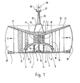
- Fig. 1 shows a vertical cross section through the center of the device of the invention.
- the inner area of the device forms a dome-shaped building 3 made of reinforced concrete, the entrances of which are designated by 2.
- the dome-shaped building 3 is supported by a plurality of pillars 4, which also serve to support the inner part of the superstructure explained below.
- the impeller 5 Above the central part of the dome-shaped building 3 is the impeller 5 with its central axis 6, which pierces the dome-shaped building 3 at the central point.
- the impeller 5 has a plurality of vanes or blades that are curved in the horizontal direction.
- the wings are made of metal, such as aluminum or steel.
- the number of blades of the impeller is not particularly limited. In order to achieve a uniform rotational movement and good use of the wind, a larger number of blades, for example 12, is preferred.
- the vanes of the impeller are connected to each other and to the central axis by means of several horizontally arranged round plates and stiffened.
- the plates 7 are preferably made of steel.
- the number of plates 7 used is also not particularly limited. It depends on the size of the impeller. For example, an embodiment with five horizontal plates 7 is preferred.
- the vertical axis 6 of the impeller 5 is supported at its upper end with the bearing 8 in the covering of the superstructure.
- bearings 9 are provided, the purpose of which, like that of the bearing 8, is to achieve the lowest possible running of the axis.
- the axis 6 transmits the movement of the impeller 5 to the gear 15, which represents the central part of the machine park arranged in the interior of the dome-shaped building 3 for generating the electrical energy.
- a horizontal axis 16 extends from the transmission 15, via which the movement from the transmission 15 is transmitted to the devices 14 for automatic control of the rotational speed and there to the generators 13 for generating the electrical energy.
- 12 denotes AC generators that are connected to the generators. The entire machine part rests on an isolated platform 17, which is used in particular to absorb vibrations.
- the superstructure which in addition to the dome-shaped building and the impeller 5 with its axis 6 represents the third essential part of the device of the invention, consists essentially of columns 18, 19 and 20 as well as beams 22 and the roof structure 21. These parts are preferred made of reinforced concrete. They all rest on the foundation 1.
- the inner columns 18, intermediate columns 19 and outer columns 20 serve to support the roof structure 21 and thus the stability of the entire superstructure.
- the roof structure 21 consists of reinforced concrete ribs which run downwards in a funnel shape towards the center of the superstructure. Its upper limit is designated 33.
- the beams 22 are of particular importance within the superstructure. They also rest on the foundation 1 and extend in the vertical direction to the roof structure 21. Preferably, four of these supports 22 are provided, which divide the device of the invention into four sectors; see. Fig. 3.
- the carrier 22 stelien on the outer periphery of the device is a single wall, which divides radially towards the center of the device and runs as two walls with different shapes in the direction of the space in which the Impeller 5 is located. In front of this space 10, the two walls reunite and thereby form the sections 11 of the delimitation of the space 10 of the impeller 5. In cross section, the carriers 22 accordingly have an approximately teardrop shape.
- the side walls 23 of the supports 22 are straight in the vertical direction, but curved in the horizontal direction. This curvature is on the two sides of a carrier 22 different. It is designed in such a way that the wind is directed in a particularly favorable manner towards the concave surfaces of the blades of the impeller 5.
- the carriers 22 are hollow inside, apart from the necessary stiffeners for their stability. These cavities in the carriers 22 serve, among other things, to accommodate the gates 26, which are provided for controlling the entry and exit of the wind into and out of the space in which the impeller 5 is located.
- the beams 22, which are made of reinforced concrete, are an essential part of the device of the invention due to their outer shape, which serves to concentrate the wind towards the wings of the impeller 5, and because of their function for receiving the gates they also serve to increase the strength of the superstructure.
- Figure 2 is a side view of the device of the invention.
- the dome-shaped building 3 with its entrances 2 and the light and ventilation openings 29 can be seen in the middle lower region.
- Above and around the dome is the superstructure with the inner columns 18, the intermediate columns 19 and the outer columns 20.
- Three supports 22 can also be seen, the different curvature of the side walls being visible on the middle one.
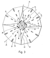
- Fig. 3 is a horizontal cross section through the device of the invention at the level of the impeller 5, i.e. above the dome-shaped building 3.
- the inner, intermediate and outer columns 18, 19 and 20 as well as the supports 22 can also be seen in this figure.
- a possible flow path of the wind is also shown in FIG. 3.
- the wind penetrates from any direction into one (or two) of the four sectors of the superstructure drawn there, which are each formed by two beams 22.
- the wind direction is shown by the arrows 24.
- the wind is concentrated and channeled by the course of the vertical walls 23 of the beams 22 in the horizontal direction, as well as in the vertical direction by the rising profile of the dome-shaped building 3 and the roof structure 21 running downwards in a funnel shape.
- gates 26 are provided with which the entry and exit of the wind into and out of the space 10 in which the impeller 5 is located can be controlled.
- the gates 26 are preferably designed as sliding gates that move on rails 27. When the gates 26 are opened for the entry of the wind, they disappear in slots 28 which are provided within the cavity of the beams 22.
- the direction of the wind emerging from the device of the invention is shown at 25 in FIG. 3.
- Fig. 4 is a horizontal cross section through the device of the invention at ground level.
- the inner area of FIG. 4 shows the circumference of the dome-shaped building 3 with the access. gen 30.
- the dome itself is reinforced by reinforced concrete ribs 31.
- the pillars 4 which bear the weight of the dome-shaped building 3 and the central area of the superstructure, can also be seen in cross section.
- In the center is the machine system with its components identified by 12 to 17.
- Fig. 4, 32 denotes the line of the outer border of the device of the invention.
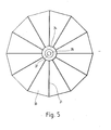
- Figure 5 is a top view of the device of the invention.
- the ribs of the roof structure 21 can be seen in this figure.
- 33 denotes the horizontal covering of the superstructure as reinforced concrete.
- This space is closed by the cover 35.
- the room 34 is surmounted by a column 36 which carries a platform 37 for measuring, news and display instruments. 38 shows a device for measuring the wind speed and 39 an antenna for communication.
- the device of the invention consists of a dome-shaped building with an inner diameter at the bottom of 90 m and a maximum inner height of 27 m. Above the central part of the dome-shaped building there is an impeller made of disassemblable parts with a diameter of 26 m and a height of 22 m, which consists of 12 blades.
- the superstructure has a diameter of approximately 200 m. It is divided into four sectors by four carriers.
- the surface of a sector of the device which is open for penetration is 142 m wide and 84 m high, that is to say has a surface area of 11928 m2.
- the opening at the entrance to the room in which the impeller is located is 8 m wide and 22 m high. Its surface is therefore 198 m 2 . This means that with this device an approximately 60-fold concentration of the wind in the direction of the blades of the impeller is achieved.
Landscapes
- Engineering & Computer Science (AREA)
- Life Sciences & Earth Sciences (AREA)
- Sustainable Development (AREA)
- Sustainable Energy (AREA)
- Chemical & Material Sciences (AREA)
- Combustion & Propulsion (AREA)
- Mechanical Engineering (AREA)
- General Engineering & Computer Science (AREA)
- Power Engineering (AREA)
- Wind Motors (AREA)
- Connection Of Motors, Electrical Generators, Mechanical Devices, And The Like (AREA)
Priority Applications (1)
| Application Number | Priority Date | Filing Date | Title |
|---|---|---|---|
| AT81103757T ATE9382T1 (de) | 1980-09-25 | 1981-05-15 | Vorrichtung zur erzeugung von elektrischer energie durch ausnutzung und steuerung der windenergie. |
Applications Claiming Priority (2)
| Application Number | Priority Date | Filing Date | Title |
|---|---|---|---|
| ES495343A ES495343A0 (es) | 1980-09-25 | 1980-09-25 | Sistema de produccion de energia electrica,mediante el apro-vechamiento y control de la fuerza del viento |
| ES495343 | 1980-09-25 |
Publications (2)
| Publication Number | Publication Date |
|---|---|
| EP0048790A1 EP0048790A1 (de) | 1982-04-07 |
| EP0048790B1 true EP0048790B1 (de) | 1984-09-12 |
Family
ID=8481108
Family Applications (1)
| Application Number | Title | Priority Date | Filing Date |
|---|---|---|---|
| EP81103757A Expired EP0048790B1 (de) | 1980-09-25 | 1981-05-15 | Vorrichtung zur Erzeugung von elektrischer Energie durch Ausnutzung und Steuerung der Windenergie |
Country Status (19)
| Country | Link |
|---|---|
| US (1) | US4415814A (enExample) |
| EP (1) | EP0048790B1 (enExample) |
| JP (1) | JPS57119178A (enExample) |
| AR (1) | AR225533A1 (enExample) |
| AT (1) | ATE9382T1 (enExample) |
| AU (1) | AU7332281A (enExample) |
| BR (1) | BR8105885A (enExample) |
| CA (1) | CA1167770A (enExample) |
| DD (1) | DD200104A5 (enExample) |
| DE (1) | DE3165963D1 (enExample) |
| DK (1) | DK345281A (enExample) |
| ES (1) | ES495343A0 (enExample) |
| GR (1) | GR74677B (enExample) |
| IL (1) | IL63310A0 (enExample) |
| IN (1) | IN154257B (enExample) |
| MA (1) | MA19246A1 (enExample) |
| MX (1) | MX149852A (enExample) |
| PT (1) | PT73472B (enExample) |
| ZA (1) | ZA815281B (enExample) |
Families Citing this family (26)
| Publication number | Priority date | Publication date | Assignee | Title |
|---|---|---|---|---|
| US4486143A (en) * | 1982-09-01 | 1984-12-04 | Mcvey Paul W | Turbine-type wind machine |
| EP0167694A1 (en) * | 1984-06-08 | 1986-01-15 | Alessandro Marinucci | Apparatus for the interception and storage of the eolian energy and for the utilization thereof |
| GB2185786B (en) * | 1986-01-07 | 1990-07-11 | Neil Douglas Warren Parkinson | Wind powered machine |
| DE8708163U1 (de) * | 1987-06-10 | 1987-08-27 | Wilhelm, Alfred, 5000 Köln | Vorrichtung zur Krafterzeugung durch Wind |
| KR910003200B1 (ko) * | 1987-07-13 | 1991-05-22 | 마쯔시다덴기산교 가부시기가이샤 | 중량검출장치 |
| FR2624210B1 (fr) * | 1987-12-04 | 1990-04-13 | Dominique Gual | Module stato-eolien realise par l'assemblage d'une turbine a ecoulement parabolique entre un socle et un dome |
| CA2018199C (fr) * | 1990-06-04 | 1993-07-27 | Gilles Ouellet | Eolienne a stator |
| GB2260372A (en) * | 1992-03-20 | 1993-04-14 | Pak Wing Wong | Wind turbine including alternative power means |
| AU5016493A (en) * | 1992-08-18 | 1994-03-15 | Four Winds Energy Corporation | Wind turbine particularly suited for high-wind conditions |
| GB2273531B (en) * | 1992-12-16 | 1995-11-01 | Joseph Kirkley Hourie | Environment compatible wind motor |
| FR2745040A1 (fr) * | 1996-02-20 | 1997-08-22 | Marques Georges | Eolienne a axe vertical de grande surface de captage sans gouvernail autoregulatrice |
| US6448669B1 (en) | 1998-12-01 | 2002-09-10 | Dillyn M. Elder | Water power generation system |
| US6191496B1 (en) | 1998-12-01 | 2001-02-20 | Dillyn M. Elder | Wind turbine system |
| DE19946389A1 (de) * | 1999-09-28 | 2001-03-29 | Viktor Otte | Wind-Energie-Konverter (WEK) mit vertikaler Rotorachse und Kombinationsströmungsprofilen |
| KR100531220B1 (ko) * | 2003-07-25 | 2005-11-25 | 유영실 | 풍력 발전장치 |
| CA2449575A1 (en) * | 2003-11-18 | 2005-05-18 | John S. Haskill | Wind-driven generator |
| US7771158B2 (en) * | 2006-02-08 | 2010-08-10 | Frank Grassi | Power towers/innovative method of power extraction using static airfoils |
| EP2258940B1 (en) * | 2009-06-02 | 2013-03-13 | Penn Anneliese | Wind power station with a darrieus rotor |
| EP2443341A4 (en) * | 2009-06-19 | 2014-05-14 | Univ Miami | WIND ENERGY SYSTEM |
| ITPI20130067A1 (it) * | 2013-07-12 | 2015-01-13 | Treecube S R L | Turbina eolica ad asse verticale |
| CN107250531A (zh) * | 2014-08-12 | 2017-10-13 | 蒋素芳 | 一种风力发电装置和系统 |
| GB2536618B (en) * | 2015-03-09 | 2019-03-06 | Bell Gordon | Air capture turbine |
| NL2016888B1 (en) | 2016-06-02 | 2018-01-12 | Ibis Power Holding B V | Electric power system for converting wind energy into electric energy and building with system |
| RU181671U1 (ru) * | 2017-07-13 | 2018-07-26 | Федеральное государственное бюджетное образовательное учреждение высшего образования "Казанский национальный исследовательский технический университет им. А.Н. Туполева-КАИ" (КНИТУ-КАИ) | Комбинированный регулируемый ветродвигатель |
| US10975839B2 (en) * | 2018-05-23 | 2021-04-13 | William Olen Fortner | Vertical axis wind turbines with V-cup shaped vanes, multi-turbine assemblies and related methods and systems |
| GB202101747D0 (en) * | 2021-02-09 | 2021-03-24 | Greenwood Warren | Wind driven Electricity Generating Apparatus and Method of Use Thereof |
Family Cites Families (6)
| Publication number | Priority date | Publication date | Assignee | Title |
|---|---|---|---|---|
| FR515331A (fr) * | 1919-04-20 | 1921-03-31 | Adrien Alfred Pache | Moteur atmosphérique actionné par le vent, avec dispositif destiné à augmenter son effet utile, utilisable comme moteur simple, double, triple, quadruple ou plus, suivant les besoins, pour obtenir de grandes puissances et une régularité de fonctionnement aussi complète que possible des appareils à actionner |
| DE922544C (de) * | 1943-10-06 | 1955-01-17 | Siemens Ag | Anordnung zur Erzeugung elektrischer Energie |
| DE867380C (de) * | 1944-06-28 | 1953-02-16 | Oskar Ludwig Kuntz | Windkraftanlage |
| GB667587A (en) * | 1950-01-06 | 1952-03-05 | William James Heppell | Improvements in or relating to wind motors |
| US4164382A (en) * | 1977-07-27 | 1979-08-14 | General Atomic Company | Wind driven power apparatus |
| US4269563A (en) * | 1979-08-09 | 1981-05-26 | Errol W. Sharak | Wind turbine |
-
1980
- 1980-09-25 ES ES495343A patent/ES495343A0/es active Granted
-
1981
- 1981-05-15 AT AT81103757T patent/ATE9382T1/de active
- 1981-05-15 DE DE8181103757T patent/DE3165963D1/de not_active Expired
- 1981-05-15 EP EP81103757A patent/EP0048790B1/de not_active Expired
- 1981-07-15 IL IL63310A patent/IL63310A0/xx unknown
- 1981-07-22 GR GR65592A patent/GR74677B/el unknown
- 1981-07-22 AU AU73322/81A patent/AU7332281A/en not_active Abandoned
- 1981-07-23 US US06/286,188 patent/US4415814A/en not_active Expired - Fee Related
- 1981-07-29 AR AR286251A patent/AR225533A1/es active
- 1981-07-29 CA CA000382771A patent/CA1167770A/en not_active Expired
- 1981-07-30 DD DD81232222A patent/DD200104A5/de unknown
- 1981-07-31 ZA ZA815281A patent/ZA815281B/xx unknown
- 1981-08-03 DK DK345281A patent/DK345281A/da not_active Application Discontinuation
- 1981-08-03 JP JP12233681A patent/JPS57119178A/ja active Pending
- 1981-08-03 PT PT73472A patent/PT73472B/pt unknown
- 1981-08-10 MA MA19446A patent/MA19246A1/fr unknown
- 1981-09-05 IN IN997/CAL/81A patent/IN154257B/en unknown
- 1981-09-15 BR BR8105885A patent/BR8105885A/pt unknown
-
1983
- 1983-07-31 MX MX188558A patent/MX149852A/es unknown
Also Published As
| Publication number | Publication date |
|---|---|
| ATE9382T1 (de) | 1984-09-15 |
| BR8105885A (pt) | 1982-06-08 |
| ZA815281B (en) | 1982-08-25 |
| CA1167770A (en) | 1984-05-22 |
| MA19246A1 (fr) | 1982-04-01 |
| IL63310A0 (en) | 1981-10-30 |
| MX149852A (es) | 1983-12-29 |
| PT73472B (en) | 1982-11-09 |
| DE3165963D1 (en) | 1984-10-18 |
| PT73472A (en) | 1981-09-01 |
| ES8200169A1 (es) | 1981-08-01 |
| EP0048790A1 (de) | 1982-04-07 |
| JPS57119178A (en) | 1982-07-24 |
| ES495343A0 (es) | 1981-08-01 |
| AR225533A1 (es) | 1982-03-31 |
| DD200104A5 (de) | 1983-03-16 |
| US4415814A (en) | 1983-11-15 |
| DK345281A (da) | 1982-03-26 |
| IN154257B (enExample) | 1984-10-13 |
| GR74677B (enExample) | 1984-07-02 |
| AU7332281A (en) | 1982-04-01 |
Similar Documents
| Publication | Publication Date | Title |
|---|---|---|
| EP0048790B1 (de) | Vorrichtung zur Erzeugung von elektrischer Energie durch Ausnutzung und Steuerung der Windenergie | |
| EP0044390A2 (de) | Vorrichtung zur Erzeugung von elektrischer Energie aus Windenergie | |
| DE202021105573U1 (de) | Solar-Carport | |
| DE3012442A1 (de) | Wellenkraftwerk | |
| CH706768A1 (de) | Anlage zur Entnahme von elektrischer Energie aus Wasserkraft. | |
| DD202326A5 (de) | Vorrichtung zur erzeugung von elektrischer energie durch ausnutzung der bewegungsenergie des meereswassers | |
| DE19636240A1 (de) | Maste für Windkraftanlagen | |
| EP0050183A1 (de) | Vorrichtung zur Erzeugung von elektrischer Energie durch Ausnutzung und Steuerung der potentiellen Energie des Meerwassers | |
| EP0235149B1 (de) | Gekapselte windkraftmaschine mit aussermittiger rotorachse | |
| DE3300049C2 (de) | Vorrichtung zum Umwandeln von durch Wind erzeugter Rotationsenergie in elektrische Energie | |
| DE102005041600B3 (de) | Windkraftanlage | |
| DE102014002588A1 (de) | Radial raffbares Membrandach | |
| DE10118407B4 (de) | Schwebeflügel-Windkraftanlage | |
| DD200754A5 (de) | Vorrichtung zur erzeugung von elektrischer energie auf einer schwimmenden basis durch ausnutzung und steuerung der potentiellen energie des meereswassers | |
| DE3844378A1 (de) | Elektrische windkraftanlage und verfahren zu deren herstellung | |
| EP0179260A2 (de) | Drehhotel | |
| CH667308A5 (de) | Mietfachanlage. | |
| DE3017303C2 (de) | Vorrichtung zur Nutzbarmachung von Energie aus der Natur | |
| EP2602479A1 (de) | Kombiwindkraftanlage | |
| DE102017002015B4 (de) | Energieerzeugungsvorrichtung | |
| DE3116396A1 (de) | Windenergiebetriebene generatorvorrichtung | |
| DE3301885A1 (de) | Windgenerator | |
| DE202005009462U1 (de) | Antennenanlage | |
| DE202004015800U1 (de) | Auftriebgestützter Wind- und Gezeitenkraftkonverter | |
| DE4344032A1 (de) | Karusselldrehtür |
Legal Events
| Date | Code | Title | Description |
|---|---|---|---|
| PUAI | Public reference made under article 153(3) epc to a published international application that has entered the european phase |
Free format text: ORIGINAL CODE: 0009012 |
|
| AK | Designated contracting states |
Designated state(s): AT BE CH DE FR GB IT LU NL SE |
|
| 17P | Request for examination filed |
Effective date: 19820916 |
|
| ITF | It: translation for a ep patent filed | ||
| GRAA | (expected) grant |
Free format text: ORIGINAL CODE: 0009210 |
|
| AK | Designated contracting states |
Designated state(s): AT BE CH DE FR GB IT LI LU NL SE |
|
| REF | Corresponds to: |
Ref document number: 9382 Country of ref document: AT Date of ref document: 19840915 Kind code of ref document: T |
|
| REF | Corresponds to: |
Ref document number: 3165963 Country of ref document: DE Date of ref document: 19841018 |
|
| ET | Fr: translation filed | ||
| PGFP | Annual fee paid to national office [announced via postgrant information from national office to epo] |
Ref country code: AT Payment date: 19850523 Year of fee payment: 5 |
|
| PG25 | Lapsed in a contracting state [announced via postgrant information from national office to epo] |
Ref country code: LU Free format text: LAPSE BECAUSE OF NON-PAYMENT OF DUE FEES Effective date: 19850531 |
|
| PGFP | Annual fee paid to national office [announced via postgrant information from national office to epo] |
Ref country code: NL Payment date: 19850531 Year of fee payment: 5 |
|
| PLBE | No opposition filed within time limit |
Free format text: ORIGINAL CODE: 0009261 |
|
| STAA | Information on the status of an ep patent application or granted ep patent |
Free format text: STATUS: NO OPPOSITION FILED WITHIN TIME LIMIT |
|
| 26N | No opposition filed | ||
| PG25 | Lapsed in a contracting state [announced via postgrant information from national office to epo] |
Ref country code: AT Effective date: 19860515 |
|
| PG25 | Lapsed in a contracting state [announced via postgrant information from national office to epo] |
Ref country code: SE Effective date: 19860516 |
|
| PG25 | Lapsed in a contracting state [announced via postgrant information from national office to epo] |
Ref country code: LI Effective date: 19860531 Ref country code: CH Effective date: 19860531 Ref country code: BE Effective date: 19860531 |
|
| BERE | Be: lapsed |
Owner name: MARTINEZ PARRA JOSE Effective date: 19860531 |
|
| PG25 | Lapsed in a contracting state [announced via postgrant information from national office to epo] |
Ref country code: NL Effective date: 19861201 |
|
| NLV4 | Nl: lapsed or anulled due to non-payment of the annual fee | ||
| GBPC | Gb: european patent ceased through non-payment of renewal fee | ||
| PG25 | Lapsed in a contracting state [announced via postgrant information from national office to epo] |
Ref country code: FR Free format text: LAPSE BECAUSE OF NON-PAYMENT OF DUE FEES Effective date: 19870130 |
|
| REG | Reference to a national code |
Ref country code: CH Ref legal event code: PL |
|
| PG25 | Lapsed in a contracting state [announced via postgrant information from national office to epo] |
Ref country code: DE Effective date: 19870203 |
|
| REG | Reference to a national code |
Ref country code: FR Ref legal event code: ST |
|
| PG25 | Lapsed in a contracting state [announced via postgrant information from national office to epo] |
Ref country code: GB Effective date: 19881118 |
|
| EUG | Se: european patent has lapsed |
Ref document number: 81103757.1 Effective date: 19870225 |