EP0047190B1 - Appareil chirurgical pour la découpe précise de la cornée - Google Patents
Appareil chirurgical pour la découpe précise de la cornée Download PDFInfo
- Publication number
- EP0047190B1 EP0047190B1 EP81400745A EP81400745A EP0047190B1 EP 0047190 B1 EP0047190 B1 EP 0047190B1 EP 81400745 A EP81400745 A EP 81400745A EP 81400745 A EP81400745 A EP 81400745A EP 0047190 B1 EP0047190 B1 EP 0047190B1
- Authority
- EP
- European Patent Office
- Prior art keywords
- support
- knife holder
- rotation
- knife
- relation
- Prior art date
- Legal status (The legal status is an assumption and is not a legal conclusion. Google has not performed a legal analysis and makes no representation as to the accuracy of the status listed.)
- Expired
Links
- 210000004087 cornea Anatomy 0.000 title claims description 20
- 241000425571 Trepanes Species 0.000 claims description 28
- 238000013519 translation Methods 0.000 claims description 19
- 210000000887 face Anatomy 0.000 claims description 7
- 239000012530 fluid Substances 0.000 claims description 3
- 230000000670 limiting effect Effects 0.000 claims description 2
- 230000014616 translation Effects 0.000 description 16
- 210000000078 claw Anatomy 0.000 description 10
- 208000031968 Cadaver Diseases 0.000 description 7
- 230000015572 biosynthetic process Effects 0.000 description 6
- 230000000295 complement effect Effects 0.000 description 6
- 230000002093 peripheral effect Effects 0.000 description 5
- 230000009471 action Effects 0.000 description 4
- 230000000694 effects Effects 0.000 description 4
- 238000011144 upstream manufacturing Methods 0.000 description 4
- 230000008901 benefit Effects 0.000 description 3
- 230000036961 partial effect Effects 0.000 description 3
- 230000035515 penetration Effects 0.000 description 3
- 238000001356 surgical procedure Methods 0.000 description 3
- 210000004369 blood Anatomy 0.000 description 2
- 239000008280 blood Substances 0.000 description 2
- 238000010586 diagram Methods 0.000 description 2
- 238000006073 displacement reaction Methods 0.000 description 2
- 238000009434 installation Methods 0.000 description 2
- 238000003973 irrigation Methods 0.000 description 2
- 239000000463 material Substances 0.000 description 2
- 239000004810 polytetrafluoroethylene Substances 0.000 description 2
- 229920001343 polytetrafluoroethylene Polymers 0.000 description 2
- 230000000284 resting effect Effects 0.000 description 2
- 210000002966 serum Anatomy 0.000 description 2
- 201000002287 Keratoconus Diseases 0.000 description 1
- 238000002679 ablation Methods 0.000 description 1
- 238000004026 adhesive bonding Methods 0.000 description 1
- 230000000903 blocking effect Effects 0.000 description 1
- 230000015556 catabolic process Effects 0.000 description 1
- 230000007423 decrease Effects 0.000 description 1
- 238000010494 dissociation reaction Methods 0.000 description 1
- 230000005593 dissociations Effects 0.000 description 1
- 239000000428 dust Substances 0.000 description 1
- 230000008030 elimination Effects 0.000 description 1
- 238000003379 elimination reaction Methods 0.000 description 1
- 239000000284 extract Substances 0.000 description 1
- 238000000605 extraction Methods 0.000 description 1
- 230000001788 irregular Effects 0.000 description 1
- 230000004048 modification Effects 0.000 description 1
- 238000012986 modification Methods 0.000 description 1
- 238000012544 monitoring process Methods 0.000 description 1
- 230000000717 retained effect Effects 0.000 description 1
- 230000002441 reversible effect Effects 0.000 description 1
- 238000010079 rubber tapping Methods 0.000 description 1
- 238000007789 sealing Methods 0.000 description 1
- 238000009964 serging Methods 0.000 description 1
- 230000007704 transition Effects 0.000 description 1
- 230000007306 turnover Effects 0.000 description 1
Images


Classifications
-
- A—HUMAN NECESSITIES
- A61—MEDICAL OR VETERINARY SCIENCE; HYGIENE
- A61F—FILTERS IMPLANTABLE INTO BLOOD VESSELS; PROSTHESES; DEVICES PROVIDING PATENCY TO, OR PREVENTING COLLAPSING OF, TUBULAR STRUCTURES OF THE BODY, e.g. STENTS; ORTHOPAEDIC, NURSING OR CONTRACEPTIVE DEVICES; FOMENTATION; TREATMENT OR PROTECTION OF EYES OR EARS; BANDAGES, DRESSINGS OR ABSORBENT PADS; FIRST-AID KITS
- A61F9/00—Methods or devices for treatment of the eyes; Devices for putting in contact-lenses; Devices to correct squinting; Apparatus to guide the blind; Protective devices for the eyes, carried on the body or in the hand
- A61F9/007—Methods or devices for eye surgery
- A61F9/013—Instruments for compensation of ocular refraction ; Instruments for use in cornea removal, for reshaping or performing incisions in the cornea
Definitions
- the present invention relates to a surgical device or "drill bit" for the precise cutting of the cornea.
- Keratoplasty requires the removal of the cornea part of the affected eye to replace it with a transplant, that is to say by a healthy part of the cornea.
- a generally circular incision is first made around the affected part.
- the incised part is then removed in a known manner. These operations are carried out under a microscope because they require very high precision and the cutting or lateral incision is carried out using a device called a drill bit.
- Such drill bits are also used in refractive surgery, to make a circular incision on the cornea, which allows, by controlling the suture, to apply stresses to the cornea resulting in a modification of its curvature.
- the invention relates to a new apparatus of the drill bit type.
- the first type includes a knife with a cylindrical blade, the circular cutting part of which is applied to the eye and is rotated to incise.
- French patent application FR-A-2 364 646 comprises a pointed and laterally sharp blade, which is fixed in an axially adjustable manner on a support having a support on the eye, to the outside of the incision line, and an internal transparent lens around which the blade can be rotated.
- the incision is made gradually by alternating rotations and depressions of the blade, and it is possible to standardize the penetration depth of the latter to a predetermined value by rotating the blade without translating that -this.
- the object of the invention is to make a perfectly circular incision with precise and equal depth over its entire perimeter, preferably with adjustment before the device is placed on the eye, knife retracted.
- the present invention offers the possibility of making one succeed directly, by action of the operator on single drive means, a phase of rotation of the blade with translation then a phase of rotation without translation with transition between the two phases when the blade forms a predetermined projection relative to other elements of the drill bit, which makes it possible to standardize the depth of the incision obtained.
- the trepan according to the invention makes it possible to make on the cornea at least two concentric incisions, with or without removal of the intermediate ring, to modify the curvature of the cornea; it also allows, thanks to its circular blade, to take a preserved graft.
- the body is provided on its outer surface with a thread cooperating with an internal thread carried by the support, and said drive means are engaged directly with the body; then, advantageously, said internal thread is carried by an element movable in rotation about the axis in the support, between two stops spaced angularly by a predetermined angle and means are provided between the body and said element on the one hand, and between said element and the support on the other hand, so that the friction forces tending to oppose the rotation of the knife holder relative to said element are different from the friction forces tending to oppose the rotation of said element relative to the support; or again, said internal thread is carried by a movable element around the axis in the support, and means are provided between the body and said element on the one hand and between said element and the support on the other hand, so that the friction forces tending to oppose the rotation of the knife holder relative to said element are less than the friction forces tending to oppose the rotation of said element relative to the support and that said element is nevertheless capable of rotation relative to the support,
- the support and the knife holder are each equipped with a first and a second stop, the first stops being fixedly carried by the support and the knife holder to constitute a limit when they come into abutment.
- one of the second stops being fixedly carried by one of the above-mentioned parts (support or knife holder) while the other of the second stops is brought to be adjustable by the other part, to constitute during their mutual contact an adjustable limit to the movement of the knife holder relative to the support in the direction of the eye, this limit corresponding to the depth of the incision to be made, a display device of the position of said stop relative to the part, consisting of an index and a graduation expressed in units of incision depth, being associated with said part and adjustable stop.
- a preferred embodiment consists in that the above-mentioned part is the knife holder, provided with a second thread and with a notched crown which is integral with it, while the adjustable stop is constituted by a shoulder d 'a threaded sleeve cooperating with said second thread, provided with an elastic pawl cooperating with said toothed crown.
- the graduation of the above display device is carried by the neck protrusions. notched ronne while the end of the aforementioned pawl defines, with the end of a mask secured to the socket, a window for reading said graduation constituting said index.
- the support is provided with a fixed wall inside the body of the knife holder, forming a fixing element for a removable lens, supplemented if necessary by an annular lens interposed between the knife and the support. .
- a drill bit which has an external support 1 comprising a rear part 1 a of substantially cylindrical shape and a foot part 1 b of substantially conical shape screwed and centered on part 1a.
- This support is hollow and has a longitudinal axis 2.
- Part 1 b is open at 3.
- the opening 3 is bordered by an anterior face 4 forming a substantially spherical crown to rest on the patient's eye and is provided of a plurality of claws 5 having dimensions sufficient to prevent the sliding of the drill bit over the eye, but nevertheless weak enough not to mark the eye; in a variant, the claws 5 are circumferentially distributed at a pitch compatible with the number of stitches to be made when the graft is placed, and have dimensions such that they form marks on the eye which indicate the points where the suture is to be performed.
- the rear part 1a of the support 1 is equipped laterally with a bearing 6 in which a rod 7 parallel to the axis 2 is capable of rotating.
- the rod 7 carries a pinion 8 while its other end is equipped with a conical bevel gear 8a, engaged with a similar pinion 8b secured to the lower end of a rod 7a, preferably oblique to the axis 2, capable of rotating in a second lateral bearing 6a of the rear part 1a of the support 1;
- the other end of the rod 7a is equipped with a manual operating button 9 fixed in rotation on the rod 7a by means of a pin 10.
- the button 9 is capable of sliding along the rod 7a and being guided in its sliding by notches 11 in which the ends of the pin 10 can move.
- a spring 12 tends to push the button 9 downwards, which has at its lower part a part 9a having side panels.
- this part 9a When this part 9a is in the position of the figure, it is placed and maintained under the effect of the spring 12 in a housing of the bearing 6a, in which it can rotate.
- This housing has an upper opening 13 having a shape complementary to that of said part 9a to allow this part 9a to pass through this opening, if it is correctly angularly oriented, when the button 9 is pulled against the effect of the spring 12.
- the bearing 6a ends in an outer face 14 in which a recess 15 has been formed also having a shape complementary to that of the part 9a but nevertheless oriented perpendicular to the opening 13 to receive the part 9a of the button in a position in which this part 9a is locked in rotation, and in which the pinion 8 can therefore no longer rotate.
- This locking can be released at any time by lifting the button 9 against the effect of the spring 12 and by replacing the part 9a in its housing located under the opening 13, in which it can freely rotate.
- a lining 16 has been placed which ensures minimal friction of the button 9 during its rotation; similarly, between the bearing 6a and the pinion 8b and between the bearing 6 and the pinions 8a and 8 are interposed with the linings, respectively 16a, 16b, 16c, ensuring minimal friction and, in the case of the linings 16b and 16c, a sealing of the rod 7 relative to the bearing 6.
- the rod 7a further carries a pinion capable of meshing with the output pinion of a geared motor assembly, for example in step-by-step advance, to allow motorization of the drill bit; in in this case, the motor can advantageously be controlled and / or controlled by a microprocessor, which displays at all times a value for the descent of the cutting edge of the knife, or the depth of incision reached.
- annular ring 17 Inside the posterior part 1 a of the support, an annular ring 17 has been placed which can rotate there.
- This ring is immobilized axially in the support by two ball bearings 18, 19 which can be replaced or supplemented by surfaces with a low coefficient of friction; in particular, between the respective balls of the bearings 18 and 19 may be interposed sections of an O-ring made of a material such as PTFE joining two by two the neighboring balls to prevent the penetration, between them, of dust liable to impede their turnover.
- the ring 17 has an outer surface 17a from which radially protrudes a radial pin 20 of small width.
- the part 1a of the support has a pin 21 projecting internally opposite the external surface 17a to serve as a stop for the pin 20.
- the ring 17 also carries an internal thread 22.
- the internal thread 22 is intended to receive an external thread 24 produced on the body 23 of a knife holder.
- the general shape of this knife holder is conical to correspond to the general shape of the support.
- the body 23 is provided with a toothed crown 25 which meshes with the pinion 8 above.
- the lower (or anterior) part of the body 23 has a transverse face 26 which forms a bearing face for a knife 27, essentially cylindrical of revolution around the axis 2, held on the knife holder by means of a clamping and centering nut 28, having a thread by which it is screwed onto a thread of the knife holder; advantageously, an arrow engraved on the outside of the nut 6 indicates the direction of rotation when screwing (FIG. 6).
- FIGS 2 and 3 illustrate an embodiment of the knife according to the invention
- Figures 4, 5, 6 show in detail the locking nut of this knife on the support face 26 above.
- the knife 27 has a wall 59 essentially cylindrical of revolution ending in a circular cutting edge 58 defining the blade of the knife, and a posterior shoulder 29 defined by a plurality of regularly distributed radial branches, here three in number, whose ends are rounded and located on the same virtual circle 30.
- Knives of different sizes can be fixed on the drill bit of the invention, depending in particular on the geometrical characteristics of the eye to be treated.
- the diameter d of the cutting edge 58 could, for example, vary between 7 and 9.5 mm with a pitch of 0.25 mm, the cutting of the shoulder 20 being identical from one knife to another.
- the knives By providing the knives with complementary threads or with suitable mutual interlocking means, it is also possible to have two knives concentrically, one inside the other, in perfectly predetermined relative positions, in particular as regards their cutting edges, for simultaneously practicing on the eye two concentric circular incisions in refractive surgery.
- the nut 28 has for its part a lower face 32 having a cut substantially or approximately complementary to that of the shoulder 29 of the knife so as to allow this shoulder to be introduced into a cylindrical interior housing 33 of the nut 28.
- This housing 33 has a diameter equal to the diameter of the circle 30, which allows, by screwing the nut, to offset its cutout relative to that of the shoulder 29 of the knife and to tighten this shoulder against the face 26 (which will include preferably a slight counterbore of shape complementary to the shape of the shoulder 29 to retain the knife against rotation when tightening the nut).
- the cylindrical peripheral face of this housing 33 serves at the same time to center the nut on the body 23, that is to say relative to the axis 2.
- the nut 28 has at its threading a recessed or unhooked part 34 whose edges spaced angularly by about 100 to 120 ° cooperate with a radial pin 35 ( Figure 1) carried by the body 23.
- the setting place of this pin is of course carried out after adjusting the nut so that the partial rotation that it allows authorizes the tightening and loosening of the knife and its extraction through the cutting of the nut.
- This arrangement makes the nut 28 impossible to dismantle and facilitates the positioning of the knife.
- Notches 36 external to the nut allow it to be maneuvered by means of a key designed for this purpose.
- FIG. 1 it can be seen that between the crown 25 and the face 26 the body 23 of the knife holder, the latter is fitted with a socket 37 provided with an internal thread by which it is screwed onto a thread 38 of the body 23.
- This socket which is shown in bottom view in FIG. 7 and in section in FIG. 8, comprises an upper flange 37a and a lower pawl 37b which is a curvilinear elastic arm cut in a skirt 37c extending the socket in its lower part.
- This arm has an internal radial protuberance 39 which cooperates with the notches of a notched crown 40 secured to the knife holder (in one piece or attached).
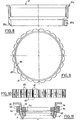
- This crown is shown in detail in Figures 9 and 10. Between its notches 41, it poses projections 42 which bear marks 43 indicating for example in tenths and half-tenths of a millimeter the depth of incision.
- the skirt 37c of the socket 37 defines with the pawl 37a a window 44 ( Figure 7) in which only one of the pins 43 appears, corresponding to the desired depth of incision.
- the support 1 has an inner wall 45 coupled to the part 1a by means of fastening elements 46 (pins).
- This inner wall on the one hand constitutes the upper raceway 18a of the balls 18, on the other hand comprises a shoulder 45a produced opposite a shoulder 23a of the knife holder to constitute fixed stops for limiting the retraction of the door -knife in the support; finally, it is internally threaded at its front end 45b to receive a lens holder part 47.
- a ring 56 of a material with a low coefficient of friction such as a split PTFE ring, to avoid jamming of the body 23, in the extreme position of retraction, against the wall 45 by mutual friction of the shoulders 45a and 23a.
- the extreme position of retraction of the body 23 relative to the wall 45 and to the part 1a of the drill bit can also be defined, in addition to or in replacement of the coming of the shoulders 45a and 23a in abutment, if necessary by means of the ring 56, by coming into contact with one of the teeth of the crown 25 of the body 23, extended above this crown (relative to the other teeth), with a pin 57 carried by the wall 45 and projecting radially outwardly relative to the latter, on the forced passage of this tooth when the body 23 reaches the position of extreme retraction; the distance, measured parallel to the axis 2, the tooth of which is thus extended relative to the other teeth of the crown 25, is less than the pitch of the thread 22 and the thread 24 so that, after the body 23 has performed one revolution relative to the ring 17 from the extreme retraction position thus defined, the extended tooth escapes the pin 57 and does not hamper the downward movement of the body 23.
- the lens-holding part 47 carries a conical lens 48 filling almost completely the interior space defined by the wall 45.
- This lens 48 permanently coupled to the part 47 by gluing or the like, has an anterior extension 48a of smaller diameter co-axial with the knife, inside the latter, and terminated by a concave face 48b.
- the face 48b is placed approximately or substantially in the spherical extension, inside the knife, of the face 4 of the base part of the support, at the same time than this one to fit the surface of the eye.
- Notches 48c provided in the lens allow its assembly or disassembly by means of a key.
- FIG. 1 In the right-hand part of FIG. 1, there is shown in section another type of lens 49 integral with a part 47 ′ similar to part 47.
- This lens 49 has a central recess 50 which, surrounded by an anterior face 49b curvature and position identical to those of the aforementioned face 48b, allows to perform operations on non-spherical corneas, having for example a cone deformation.
- This lens has two wires 49a which cross at the center of the space 50 to form a centering reticle.
- the lens 48-49 is fixed relative to the support 1.
- the anterior extension 48a of the lens 48 (or the similar extension of the lens 49) is connected to the upper part of the lens by a face 48b oriented approximately transversely to the axis 2 , and turned downwards, that is to say towards the knife 27, above the latter; in the example illustrated, this face 48d has a frustoconical shape of revolution around the axis 2, the top of the cone being turned downward, to facilitate the evacuation of air when, when using a lens of the type illustrated at 47 in the left-hand part of FIG.
- the interior of the drill bit is placed in depression with respect to the exterior by means of arrangements which will be described later;
- the face 48b could however have other shapes, and for example a planar shape or a concave shape similar to that of the face 48b.
- the outside diameter of the cylindrical wall 59 of the knife 27 is sufficiently smaller than the inside diameter of the annular surface 4, which defines the minimum inside diameter of the part 1b
- the annular lens 61 advantageously has a concave face 61a extending the face 48b of the lens 48 to the face 4 to bear on the eye simultaneously to these, by marrying her; towards the inside of the drill bit, it may have a flat face 61 b, perpendicular to the axis 2 as illustrated, which allows the assembly formed by the lens 48 (or 49) and the lens 61 to provide two different magnifications respectively for the inside and the outside of the circular knife, or a face having a complementary shape from that of face 48d to provide uniform magnification.
- the support 1 is provided with end pieces 51 (two, only one of which is visible in the figure) to connect the interior space of the drill bit (between walls 45 and walls 1a, 1b) to, on the one hand, a source of fluid, on the other hand, a source of aspiration making it possible to create a partial vacuum in the operating field, to thus press the drill bit on the eye and immobilize it as well as possible, and a circulation of aseptic fluid in this field, when using a non-hollow lens of the type illustrated for example at 48 in the left part of FIG. 1; this depression and this circulation are facilitated by an appropriate conformation of the interior space of the drill bit.
- a microprocessor continuously monitors and controls the pressure prevailing inside the drill bit to detect the presence of any air bubbles and control their elimination.
- the respective refractive indices of the lenses 48 and 61 are different, lower for the main lens 48 and higher for the lens 61; by way of nonlimiting example, the lens 48 may have a refractive index of the order of 140 to 150, and the lens 61 a refractive index of the order of 180.
- claws 5 ′ of the type mentioned above are supported by a washer 5a which can slide freely in the nose of the support 1b.
- a washer 52 is screwed into the nose of the support with a large pitch (2.5 to 3 mm) and is connected by pins 53 through openings 54 formed in part 1 to an external operating ring 55.
- the claws 5' can go up and retract into the surface 4.
- the claws come out from 6 to 7 tenths of a millimeter and they are kept pressed into the eye under the action of the washer 52.
- the operator placed the knife 27 on the face 26 of the knife holder 23 and locked it there by means of the nut 28. This operation was only possible after removing part 1b of the holder. part 1a. To achieve this blocking, he will have used a key acting on the notches 36 of the nut 28 having previously placed the button 9 in its fully locked or blocked position of the device.
- the 5 'claw version retractable it will carry out this installation after having retracted the claws. Thanks to these means, the positioning precision can be very high, the lens being a fixed element of the drill bit and resting directly on the eye.
- the drill bit is then gripped by its claws 5 or 5 'on the surface of the eye.
- the subjugation is strengthened by switching on the suction-irrigation device which extracts the air from the space closed by the knife holder, the support 1 and the eye and replaces it with a physiological serum.
- This rotation is also slightly less than 360 ° and stops when the stops 20 and 21 cooperate again. It made it possible to equalize the depth of the incision over its entire periphery by easing the torsional and shear stresses which the cornea underwent during cutting.
- the knife is then raised by continuing the rotation in the same direction of the button 9 until the end of travel stop 45a, 23a, 56 and / or 25, 57.
- any suitable means can be used so that the frictional forces tending to oppose the rotation of the part 23 relative to the part 17 are different from the frictional forces tending to oppose the rotation of the part 17 relative to the support 1, in order to obtain such a sequence.
- FIGS. 12 to 14 where the same references have been used as for the preceding figures to designate parts or the like, show an alternative embodiment in which the stops 20, 21 and 57 are eliminated and the bearings at balls 18 and 19 replaced by surfaces with low coefficient of friction, any other mode of axial immobilization of the annular ring 17 in the support 1 with the possibility of relative rotation around the axis 2 can be chosen in the context of this variant as in the previous one.
- the peripheral face 17a that the ring 17 has in the direction of a distance relative to the axis 2 is cylindrical of revolution around the latter, and the part 1a of the support 1 has a face 1 facing it. c facing the axis 2, and also cylindrical of revolution around it, with a diameter greater than that of the face 17a.
- an intermediate ring 63 having an outer peripheral face 63a cylindrical of revolution around the axis 2, with a diameter substantially identical to that of the face 1c of the support 1, with which it is in contact with the possibility of relative rotation, the friction forces tending to oppose this rotation being greater than the friction forces tending to oppose the rotation of the body 23 of the knife holder relative to the ring 17, at the thread 24 and tapping 22; for example, the intermediate ring 63 is split at 64, and forced into the interior of part 1a of the support, to come into intimate contact, under prestressing, by its face 63a with the face 1c of this part 1 at.
- the intermediate ring 63 Opposite the face 17a of the ring 17, the intermediate ring 63 has an inner peripheral face 63b of cylindrical revolution around the axis 2 with a diameter preferably significantly higher than that of the face 17a to allow free relative rotation.
- the intermediate ring 63 is also freely mounted between the surfaces with a low coefficient of friction replacing, in this variant, the respective bearing surfaces, on the support 1, of the balls 19 and 20 of the variant illustrated in FIG. 1.
- the ring 63 is drilled radially right through the housing for balls whose diameter is greater than the thickness of the ring 63.
- One of these holes is advantageously constituted by the slot 64; in the example illustrated, two holes 64a and 64b are also provided, the three holes 64, 64a, 64b being arranged at 120 ° relative angular deviation, and receiving balls at the rate of one hole, respectively 65 , 65a, 65b, free mounted.
- each of these balls is received in a notch, respectively 66, 66a, 66b, arranged in the cylindrical outer face 17a.
- notches are identical and have, seen in section through a transverse plane with respect to the axis 2, as in particular in FIGS. 13 and 14, an approximately triangular shape defined by two plane faces parallel to the axis 2, for example substantially or approximately perpendicular to each other, one of which is located upstream if one refers to a predetermined direction 67 of rotation of the body 23 of the knife holder relative to the support 1 in the direction of descent of the knife, towards the eye of the patient, is entirely located downstream of a plane joining the axis 2 at its junction with the face 17a of the ring 17 by forming with this plane a dihedral of an angle // less than 90 "but greater than 0 ° and the other of which, located downstream of the first, is entirely located upstream of a plane joining the axis 2 to its junction with the face 17a of the ring 17, forming with this plane a dihedral of angle ⁇ greater than 90 ° but less than 180 °.
- the dimensions of the notches are such that, when engaged as much as possible in such a notch, the corresponding ball protrudes from the face 17a and has, inside the corresponding bore of the intermediate ring 63, a zone located in the immediate vicinity of face 1 c of part 1 a of the support without, however, coming into contact with this face 1 a.
- the shoulder 37a of the sleeve 37 abuts against the shoulder 17b of the ring 17 and the continued driving of the body 23 in rotation in the direction 67 causes this makes a joint rotation of the ring 17, and of the ring 63 by means of the balls 65a, 65b in abutment, with friction of the face 63a of the latter against the face 1c of the part 1a of the support; in the case of this variant, therefore, the rotation of the knife without lowering is carried out by driving the body 23 of the knife holder in the same direction as during the descent, with a slightly greater force since the rotation of the ring 63 relative to the support 1 then replaces the rotation of the body 23 relative to the ring 17.
- angle of rotation without lowering the knife is not limited in this case.
- each ball 65, 65a, 65b is then pushed outwards by a cam effect which is applied to it by the face of the corresponding notch placed downstream if we refer to direction 67, and therefore comes to the pressure contact of face 1 c of part 1 a of support 1.
- FIG. 14 diagrams the breakdown of the forces then occurring at the level of the ball 65, an identical phenomenon occurring at the level of the balls 65a and 65b.
- IX designates the angle formed by said downstream face of the notch 66 (if one refers to the direction 67) with the tangent to the face 1c at the point of contact of the ball with the latter.
- F designates the force applied to the ball 65 by the ring 17, via the notch 66, along the bisector of the angle (x.
- the drill bit according to the present invention allows optimal conditions to be met to ensure good trepanning of the cornea. Indeed, the adjustment of the depth of incision is carried out before the installation of the device, which eliminates a large number of false operations and misadjustments during operation.
- the depth of the incision can for example be adjusted from 0 to 1.2 mm from five to five hundredths. Therefore, one can practice lamellar trepanations, even deep, because the depth of the incision is uniform thanks to the rotation without axial movement at the end of the operation.
- the imprints left by the claws will mark the overlock to be produced and may constitute pilot holes well perpendicular to the surface of the eye over most of the thickness crossed by the wire, which decreases the tendency of the overlocking thread to locally incise the edges of its penetration holes with the consequence of a relaxation of its tension.
- the knives apart from being disposable, are interchangeable. It is thus possible, using a single drill bit, to make trepanations of different diameters (for example 7 to 9.5 mm from 25 hundredths to 25 hundredths).
- the lenses fixed to the drill bit can be adapted to the shape of the diseased eye (for example having a keratoconus) and the whole drill bit can be sterilized in an autoclave.
- the invention finds an interesting application in the field of opthalmological surgery.
Landscapes
- Health & Medical Sciences (AREA)
- Ophthalmology & Optometry (AREA)
- Heart & Thoracic Surgery (AREA)
- Surgery (AREA)
- Engineering & Computer Science (AREA)
- Biomedical Technology (AREA)
- Nuclear Medicine, Radiotherapy & Molecular Imaging (AREA)
- Vascular Medicine (AREA)
- Life Sciences & Earth Sciences (AREA)
- Animal Behavior & Ethology (AREA)
- General Health & Medical Sciences (AREA)
- Public Health (AREA)
- Veterinary Medicine (AREA)
- Surgical Instruments (AREA)
- Prostheses (AREA)
Priority Applications (2)
| Application Number | Priority Date | Filing Date | Title |
|---|---|---|---|
| AT81400745T ATE12345T1 (de) | 1980-09-03 | 1981-05-11 | Chirurgisches geraet zum genauen herausschneiden der hornhaut des auges. |
| CA000382117A CA1175314A (en) | 1980-09-03 | 1981-07-21 | Surgical apparatus for precisely cutting out the cornea |
Applications Claiming Priority (2)
| Application Number | Priority Date | Filing Date | Title |
|---|---|---|---|
| FR8019014A FR2489141A1 (fr) | 1980-09-03 | 1980-09-03 | Appareil chirurgical pour la decoupe precise de la cornee |
| FR8019014 | 1980-09-03 |
Publications (3)
| Publication Number | Publication Date |
|---|---|
| EP0047190A2 EP0047190A2 (fr) | 1982-03-10 |
| EP0047190A3 EP0047190A3 (en) | 1982-03-24 |
| EP0047190B1 true EP0047190B1 (fr) | 1985-03-27 |
Family
ID=9245615
Family Applications (1)
| Application Number | Title | Priority Date | Filing Date |
|---|---|---|---|
| EP81400745A Expired EP0047190B1 (fr) | 1980-09-03 | 1981-05-11 | Appareil chirurgical pour la découpe précise de la cornée |
Country Status (5)
| Country | Link |
|---|---|
| US (1) | US4429696A (show.php) |
| EP (1) | EP0047190B1 (show.php) |
| JP (1) | JPS5778853A (show.php) |
| DE (1) | DE3169511D1 (show.php) |
| FR (1) | FR2489141A1 (show.php) |
Families Citing this family (58)
| Publication number | Priority date | Publication date | Assignee | Title |
|---|---|---|---|---|
| FR2556953B1 (fr) * | 1983-12-21 | 1986-05-16 | Hanna Khalil | Appareil chirurgical pour keratotomie radiaire |
| DE3433581C2 (de) * | 1984-09-13 | 1986-08-07 | Fa. Carl Zeiss, 7920 Heidenheim | Vorrichtung zur lamellierenden, refraktiven Hornhautchirurgie |
| US4763651A (en) * | 1984-11-08 | 1988-08-16 | Allergan, Inc. | Trephine and method |
| EP0208950A3 (de) * | 1985-06-27 | 1987-12-16 | Patrik Dr. med. Gründler | Vorrichtung zur Transplantation der Cornea des menschlichen Auges |
| US4718420A (en) * | 1986-03-06 | 1988-01-12 | Lemp Michael A | Method and apparatus for trephining corneal tissue in preparation for keratoplasty |
| EP0239409A1 (en) * | 1986-03-28 | 1987-09-30 | Life Technology Research Foundation | Robot for surgical operation |
| US4807623A (en) * | 1986-05-30 | 1989-02-28 | David M. Lieberman | Device for simultaneously forming two incisions along a path on an eye |
| DE3707004A1 (de) * | 1987-03-05 | 1988-09-15 | Krumeich Joerg H | Schneidgeraet zum ausschneiden einer kreisrunden hornhautscheibe |
| US6051023A (en) * | 1987-06-15 | 2000-04-18 | Keravision, Inc. | Corneal curvature adjustment ring and apparatus for making a cornea |
| US4766897A (en) * | 1987-06-16 | 1988-08-30 | Heinz Smirmaul | Capsulectomy surgical instrument |
| US4796623A (en) * | 1987-07-20 | 1989-01-10 | The Cooper Companies, Inc. | Corneal vacuum trephine system |
| FR2648702A1 (fr) * | 1989-06-23 | 1990-12-28 | Hanna Khalil | Lentille pour epikeratophakie et keratotome notamment destine a la realisation d'une incision de reception d'une telle lentille |
| US5133726A (en) * | 1990-02-14 | 1992-07-28 | Ruiz Luis A | Automatic corneal shaper |
| FR2660547B1 (fr) * | 1990-04-09 | 1993-07-09 | Guerin Daniel | Appareil chirurgical pour realiser une decoupe conique de la cornee. |
| FR2660859B1 (fr) * | 1990-04-12 | 1992-07-10 | Hanna Khalil | Keratotome destine a la realisation d'incisions arciformes. |
| GB9009411D0 (en) * | 1990-04-26 | 1990-06-20 | Mahmud Ahmed S | Contact lens knife for cataract surgery |
| FR2670670B1 (fr) * | 1990-12-20 | 1997-11-14 | Khalil Hanna | Instrument de chirurgie corneenne. |
| FR2670669B1 (fr) * | 1990-12-20 | 1993-03-12 | Hanna Khalil | Instrument de correction chirurgicale de l'astigmatisme. |
| US5290301A (en) * | 1991-09-10 | 1994-03-01 | Lieberman David M | Cam guided corneal trephine |
| US5312428A (en) * | 1991-10-10 | 1994-05-17 | Lieberman David M | Corneal punch and method of use |
| CA2121036A1 (en) * | 1991-10-11 | 1993-04-15 | Clarence E. Giraud | Improved sectioning device for lamellar surgery |
| US6565584B1 (en) | 1992-04-10 | 2003-05-20 | Addition Technology, Inc. | Device and method for inserting a biocompatible material into the corneal stroma |
| ATE206031T1 (de) * | 1992-04-10 | 2001-10-15 | Keravision Inc | Zentrierende, mit vakuum arbeitende führungsvorrichtung und dissektor für die hornhaut |
| US6966927B1 (en) | 1992-08-07 | 2005-11-22 | Addition Technology, Inc. | Hybrid intrastromal corneal ring |
| JP2789134B2 (ja) * | 1992-09-28 | 1998-08-20 | ファイザー・インク. | 糖尿病の合併症を制御する置換ピリミジン類 |
| US5486188A (en) * | 1993-11-15 | 1996-01-23 | Smith; Alan D. | Keratoscopic surgical instrument for making radial and arcuate corneal incisions |
| EP0738128B1 (en) * | 1994-01-07 | 2004-09-01 | Addition Technology, Inc | System for inserting material into corneal stroma |
| US5649944A (en) * | 1994-08-12 | 1997-07-22 | Collins; Joseph Patrick | Apparatus for preparing cornea material for tabbed (sutureless) transplantation |
| US5755785A (en) * | 1994-08-12 | 1998-05-26 | The University Of South Florida | Sutureless corneal transplantation method |
| US5584881A (en) * | 1994-08-12 | 1996-12-17 | Rowsey; J. James | Sutureless corneal transplantation apparatus and method |
| US6175754B1 (en) | 1995-06-07 | 2001-01-16 | Keravision, Inc. | Method and apparatus for measuring corneal incisions |
| US6051009A (en) | 1996-02-07 | 2000-04-18 | Hellenkamp; Johann F. | Automatic surgical device for cutting a cornea and a cutting blade assembly and control assembly |
| US20070244496A1 (en) * | 1996-02-07 | 2007-10-18 | Hellenkamp Johann F | Automatic surgical device and control assembly for cutting a cornea |
| US7166117B2 (en) * | 1996-02-07 | 2007-01-23 | Hellenkamp Johann F | Automatic surgical device and control assembly for cutting a cornea |
| US5624456A (en) * | 1996-02-07 | 1997-04-29 | Hellenkamp; Johann F. | Automatic surgical device for cutting a cornea |
| US6007553A (en) * | 1996-02-07 | 1999-12-28 | Hellenkamp; Johann F. | Automatic surgical device control assembly for cutting a cornea |
| US6143010A (en) * | 1997-07-18 | 2000-11-07 | Kera Vision Inc. | Corneal vacuum centering device |
| US6582445B1 (en) * | 1998-03-11 | 2003-06-24 | Visx, Incorporated | Trephine for lamellar keratectomy |
| US6358260B1 (en) | 1998-04-20 | 2002-03-19 | Med-Logics, Inc. | Automatic corneal shaper with two separate drive mechanisms |
| US6183488B1 (en) | 1998-11-06 | 2001-02-06 | Med-Logics, Inc. | Vacuum ring with linear bearings for an automated corneal shaper |
| US6702832B2 (en) | 1999-07-08 | 2004-03-09 | Med Logics, Inc. | Medical device for cutting a cornea that has a vacuum ring with a slitted vacuum opening |
| US6699285B2 (en) | 1999-09-24 | 2004-03-02 | Scieran Technologies, Inc. | Eye endoplant for the reattachment of a retina |
| US6428508B1 (en) | 2000-02-01 | 2002-08-06 | Enlighten Technologies, Inc. | Pulsed vacuum cataract removal system |
| US6663644B1 (en) | 2000-06-02 | 2003-12-16 | Med-Logics, Inc. | Cutting blade assembly for a microkeratome |
| US6613061B1 (en) * | 2000-09-08 | 2003-09-02 | Randall J. Olson | Device for transplanting a cornea on a patient's eye |
| EP1186281B1 (en) * | 2000-09-08 | 2006-11-15 | Luigi Olivieri | Apparatus for corneal surgery |
| FR2815247B1 (fr) * | 2000-10-12 | 2002-12-20 | Moria Sa | Dispositif de chirurgie corneenne |
| US6425905B1 (en) | 2000-11-29 | 2002-07-30 | Med-Logics, Inc. | Method and apparatus for facilitating removal of a corneal graft |
| US7311700B2 (en) | 2000-11-29 | 2007-12-25 | Med-Logics, Inc. | LASIK laminar flow system |
| KR100410729B1 (ko) * | 2001-05-28 | 2003-12-18 | 에이스전자(주) | 잠금장치를 갖는 진공청소기용 스위치모듈의 일체화 구조 |
| AU2003216546A1 (en) * | 2002-03-07 | 2003-09-22 | Stephen Glenn Slade | Ultrasonic microkeratome |
| US7780689B2 (en) * | 2003-04-07 | 2010-08-24 | Technolas Perfect Vision Gmbh | Bar-link drive system for a microkeratome |
| US20070083221A1 (en) * | 2005-10-12 | 2007-04-12 | Sismed, Llc | Precision trephine |
| US20070083087A1 (en) * | 2005-10-12 | 2007-04-12 | Sismed, Llc | Fixator with membrane |
| GB2465758B (en) * | 2008-11-27 | 2012-09-12 | Philip Douglas Weston | Trephine with transparent casing |
| US10149785B2 (en) | 2016-01-04 | 2018-12-11 | Kyle Thistle | Device and method for trephine alignment |
| EP3661466B1 (en) * | 2017-08-04 | 2024-10-16 | CorneaGen Inc. | Device for tissue dissection in corneal transplants |
| EP3768205B1 (en) | 2018-03-20 | 2023-05-03 | The Regents Of The University Of California | Docking system to stabilize eyeball during intraocular surgery |
Family Cites Families (7)
| Publication number | Priority date | Publication date | Assignee | Title |
|---|---|---|---|---|
| FR1106449A (fr) * | 1954-08-12 | 1955-12-19 | Trépan chirurgical | |
| US2838050A (en) * | 1956-01-11 | 1958-06-10 | George P Pilling & Son Company | Trephine for corneal grafting |
| US3074407A (en) | 1956-09-17 | 1963-01-22 | Marguerite Barr Moon Eye Res F | Surgical devices for keratoplasty and methods thereof |
| CH620111A5 (show.php) * | 1976-09-17 | 1980-11-14 | Univ Melbourne | |
| DE2811869C2 (de) * | 1978-03-17 | 1985-10-31 | Volker 6900 Heidelberg Geuder | Trepan für die Keratoplastik |
| US4236519A (en) | 1978-04-06 | 1980-12-02 | Russa Joseph A | Corneal punch |
| US4336805A (en) | 1979-03-05 | 1982-06-29 | Heinz Smirmaul | Corneal trephine |
-
1980
- 1980-09-03 FR FR8019014A patent/FR2489141A1/fr active Granted
-
1981
- 1981-05-11 DE DE8181400745T patent/DE3169511D1/de not_active Expired
- 1981-05-11 EP EP81400745A patent/EP0047190B1/fr not_active Expired
- 1981-07-21 US US06/285,684 patent/US4429696A/en not_active Expired - Lifetime
- 1981-09-03 JP JP56139214A patent/JPS5778853A/ja active Pending
Also Published As
| Publication number | Publication date |
|---|---|
| EP0047190A3 (en) | 1982-03-24 |
| EP0047190A2 (fr) | 1982-03-10 |
| JPS5778853A (en) | 1982-05-17 |
| FR2489141B1 (show.php) | 1985-05-03 |
| DE3169511D1 (en) | 1985-05-02 |
| FR2489141A1 (fr) | 1982-03-05 |
| US4429696A (en) | 1984-02-07 |
Similar Documents
| Publication | Publication Date | Title |
|---|---|---|
| EP0047190B1 (fr) | Appareil chirurgical pour la découpe précise de la cornée | |
| EP0147318B1 (fr) | Appareil chirurgical pour kératotomie radiaire | |
| EP0525098B1 (fr) | Keratotome destine a la realisation d'incisions arciformes | |
| EP0404689B1 (fr) | Lentille pour épikératophakie et kératotome notamment destiné à la réalisation d'une incision de réception d'une telle lentille | |
| EP2449985B1 (fr) | Fraiseuse orthopédique de préparation osseuse, en particulier de préparation glénoïdienne | |
| EP1335672B1 (fr) | Dispositif de forage comprenant un trepan recuperateur d'os | |
| FR2768917A1 (fr) | Poignee reutilisable d'instrument | |
| EP1189547A2 (fr) | Dispositif de securite comportant une butee pour outil de forage utilisable notamment en chirurgie dentaire et dispositif de precalibrage et de memorisation de la profondeur de forage | |
| EP0308410B1 (fr) | Dispositif d'acces atraumatique au circuit sanguin a fonctionnement rotatif | |
| EP0340698A2 (fr) | Instrument ophtalmologique | |
| EP3419530A1 (fr) | Dispositif pour le couplage stérile d'un instrument chirurgical percutané et d'un outil d'entrainement et méthode pour réaliser un tel couplage | |
| EP3772346B1 (fr) | Fixateur de volet crânien | |
| EP0895765A1 (fr) | Appareil chirugical pour réaliser une découpe lamellaire de cornée | |
| EP2364125B1 (fr) | Dispositif dentaire pour combler temporairement l'edentement consecutif a l'extraction d'une dent | |
| FR2665356A1 (fr) | Cornee artificielle. | |
| FR2935255A1 (fr) | Ensemble d'osteosynthese et systeme chirurgical pour pratiquer l'osteosynthese comprenant un tel ensemble. | |
| FR2676353A1 (fr) | Plaque d'osteotomie tibiale ou analogue. | |
| FR2595243A1 (fr) | Couteau pour la chirurgie du segment anterieur de l'oeil | |
| EP0895464A1 (fr) | Emballage pour le pliage des implants intraoculaires | |
| FR2631545A1 (fr) | Applicateur pour l'implantation epicorneenne de lentilles souples | |
| FR2676358A1 (fr) | Dispositif intra-oculaire implantable dans le sac capsulaire. | |
| FR2818119A1 (fr) | Trepan pour le prelevement d'une calotte corneosclerale d'un oeil de donneur | |
| WO2005072663A1 (fr) | Pince de prehension gastrique | |
| FR3141852A1 (fr) | Punch de découpe partitionnée d’un greffon cornéal et porte-lame correspondant | |
| EP2389903B1 (fr) | Système pour réaliser une arthrodèse entre deux vertèbres et ancillaires de pose |
Legal Events
| Date | Code | Title | Description |
|---|---|---|---|
| PUAI | Public reference made under article 153(3) epc to a published international application that has entered the european phase |
Free format text: ORIGINAL CODE: 0009012 |
|
| PUAL | Search report despatched |
Free format text: ORIGINAL CODE: 0009013 |
|
| AK | Designated contracting states |
Designated state(s): AT BE CH DE FR GB IT LI LU NL SE |
|
| AK | Designated contracting states |
Designated state(s): AT BE CH DE FR GB IT LI LU NL SE |
|
| 17P | Request for examination filed |
Effective date: 19820416 |
|
| RAP1 | Party data changed (applicant data changed or rights of an application transferred) |
Owner name: LABORATOIRES HYDRON |
|
| ITF | It: translation for a ep patent filed | ||
| GRAA | (expected) grant |
Free format text: ORIGINAL CODE: 0009210 |
|
| AK | Designated contracting states |
Designated state(s): AT BE CH DE FR GB IT LI LU NL SE |
|
| PG25 | Lapsed in a contracting state [announced via postgrant information from national office to epo] |
Ref country code: NL Effective date: 19850327 Ref country code: AT Effective date: 19850327 |
|
| REF | Corresponds to: |
Ref document number: 12345 Country of ref document: AT Date of ref document: 19850415 Kind code of ref document: T |
|
| PG25 | Lapsed in a contracting state [announced via postgrant information from national office to epo] |
Ref country code: SE Effective date: 19850330 |
|
| REF | Corresponds to: |
Ref document number: 3169511 Country of ref document: DE Date of ref document: 19850502 |
|
| PG25 | Lapsed in a contracting state [announced via postgrant information from national office to epo] |
Ref country code: LU Free format text: LAPSE BECAUSE OF NON-PAYMENT OF DUE FEES Effective date: 19850531 |
|
| NLV1 | Nl: lapsed or annulled due to failure to fulfill the requirements of art. 29p and 29m of the patents act | ||
| PLBE | No opposition filed within time limit |
Free format text: ORIGINAL CODE: 0009261 |
|
| STAA | Information on the status of an ep patent application or granted ep patent |
Free format text: STATUS: NO OPPOSITION FILED WITHIN TIME LIMIT |
|
| 26N | No opposition filed | ||
| PG25 | Lapsed in a contracting state [announced via postgrant information from national office to epo] |
Ref country code: GB Effective date: 19890511 |
|
| PG25 | Lapsed in a contracting state [announced via postgrant information from national office to epo] |
Ref country code: LI Effective date: 19890531 Ref country code: CH Effective date: 19890531 Ref country code: BE Effective date: 19890531 |
|
| REG | Reference to a national code |
Ref country code: FR Ref legal event code: TP |
|
| REG | Reference to a national code |
Ref country code: GB Ref legal event code: 732 |
|
| GBPC | Gb: european patent ceased through non-payment of renewal fee | ||
| REG | Reference to a national code |
Ref country code: CH Ref legal event code: PL |
|
| REG | Reference to a national code |
Ref country code: FR Ref legal event code: CL |
|
| PGFP | Annual fee paid to national office [announced via postgrant information from national office to epo] |
Ref country code: FR Payment date: 20000510 Year of fee payment: 20 |
|
| PGFP | Annual fee paid to national office [announced via postgrant information from national office to epo] |
Ref country code: DE Payment date: 20000512 Year of fee payment: 20 |