EP0046484A2 - Multi-axle articulated vehicle - Google Patents
Multi-axle articulated vehicle Download PDFInfo
- Publication number
- EP0046484A2 EP0046484A2 EP81104302A EP81104302A EP0046484A2 EP 0046484 A2 EP0046484 A2 EP 0046484A2 EP 81104302 A EP81104302 A EP 81104302A EP 81104302 A EP81104302 A EP 81104302A EP 0046484 A2 EP0046484 A2 EP 0046484A2
- Authority
- EP
- European Patent Office
- Prior art keywords
- articulated
- brake
- primary
- vehicle according
- car
- Prior art date
- Legal status (The legal status is an assumption and is not a legal conclusion. Google has not performed a legal analysis and makes no representation as to the accuracy of the status listed.)
- Granted
Links
Images


Classifications
-
- B—PERFORMING OPERATIONS; TRANSPORTING
- B62—LAND VEHICLES FOR TRAVELLING OTHERWISE THAN ON RAILS
- B62D—MOTOR VEHICLES; TRAILERS
- B62D47/00—Motor vehicles or trailers predominantly for carrying passengers
- B62D47/02—Motor vehicles or trailers predominantly for carrying passengers for large numbers of passengers, e.g. omnibus
- B62D47/025—Motor vehicles or trailers predominantly for carrying passengers for large numbers of passengers, e.g. omnibus articulated buses with interconnecting passageway, e.g. bellows
-
- B—PERFORMING OPERATIONS; TRANSPORTING
- B62—LAND VEHICLES FOR TRAVELLING OTHERWISE THAN ON RAILS
- B62D—MOTOR VEHICLES; TRAILERS
- B62D53/00—Tractor-trailer combinations; Road trains
- B62D53/04—Tractor-trailer combinations; Road trains comprising a vehicle carrying an essential part of the other vehicle's load by having supporting means for the front or rear part of the other vehicle
- B62D53/06—Semi-trailers
Definitions
- the invention relates to an articulated vehicle with a plurality of axles, in particular an articulated bus, which has a primary and secondary car, in which at least the axis of the secondary car is driven via a drive motor, in particular associated with the secondary car, and in which the secondary car is connected to the primary car via an articulated connection , in particular the front axle of the primary car being provided for steering the vehicle.
- Articulated vehicles of this type are known as articulated buses.
- a slewing ring is arranged between the primary carriage and the secondary carriage, which forms the pivot point of the secondary carriage to the primary carriage, the vehicle bodies being replaced laterally by bellows in this area.
- the secondary car forms an articulation angle with the primary car and therefore the thrust forces of the secondary car, depending on the articulation angle, act differently on the primary car along a tangent that is to be thought of as the circle formed by the curve to be driven . Without special support between the primary and secondary cars, this would result in the primary car being severely impaired in its cornering position.
- the invention has for its object to design an articulated vehicle, in particular an articulated bus so that it can be safely controlled even on wet or slippery road surfaces, even when cornering heavily, without the vehicle breaking out or kinking between the secondary and the primary car needs to be feared.
- the invention consists in that an articulated brake is provided which acts on the articulated connection as a function of the articulation angle between the primary and secondary car.
- an articulated brake acts on the articulated connection as a function of the articulation angle between the primary and secondary car.
- the articulated brake can develop its maximum braking force so that the articulation angle can be determined beforehand, so that a further increase in the articulation angle can no longer occur.
- the articulated brake is inefficient and increases its braking force to the extent by the bend angle is increased by a ven mars originally K.
- the braking forces perpendicular to the direction of thrust of the secondary carriage can only act on the primary carriage between surfaces suitably provided on the joint. Only significantly smaller braking forces are required for this.
- the joint brake can be for example a pneumatically operated R egg environment brake.
- Articulated vehicles of this type are usually equipped with compressed air units, which can therefore also be used to actuate the articulated brake without the need to provide an additional auxiliary power supply to a vehicle with the articulated brake according to the invention.
- a friction brake can be effectively arranged in the area of the connection between the two car halves and act in such a way that it can prevent a further increase in this angle at the largest permitted articulation angle.
- the brake can of course also be an oil pressure-actuated disc brake.
- a mechanical step switch is provided in the area of the slewing ring, which consists of a step wheel that increases its circumference in steps and comes into contact with mechanical switching points when the appropriate kink angle is reached.
- the switching points can control the compressed air supply to the friction brake via solenoid valves when acted on by the stepped wheel. In most cases, such a tap change will suffice to allow the braking effect to occur constantly within the angle range defined by the tap changer. It can also be inexpensive to provide a stepless switch that enables angle-dependent control.
- This configuration also opens up the possibility of triggering other control processes. For example, it is possible to trigger a warning signal for the driver when the maximum articulation angle is reached or, for automatic transmissions and reverse driving, where the maximum articulation angle can be reached, to automatically switch the reverse gear into neutral. This avoids overloading the chassis.
- the articulated brake is applied when the service brake is actuated. This can prevent the secondary car from breaking out compared to the primary car when the brakes are applied hard. In particular, it is fixed in its position in relation to the primary carriage by fully applying the articulated brake. Rolling movements or a lateral displacement can then no longer occur.
- both the service brake and the articulated brake are applied via the switches.
- the result of this is that no greater than the maximum articulation angle can occur, since the vehicle is braked immediately in this case. Damage that would be caused to the body of both the primary and the secondary car when this angle is exceeded can be effectively avoided in this way.
- steering shock absorbers can also be provided in a favorable manner between the primary and the secondary vehicle, each of which is located on the opposite vehicle support sides and can be arranged at an angle to the longitudinal axis of the vehicle.
- These steering shock absorbers have the advantage that they can dampen a rolling movement of the secondary carriage when driving straight ahead.
- the articulated brake can be controlled in such a way that it occurs at small articulation angles, such as, for example. caused by rolling movements, does not respond. This control could also be carried out while driving straight ahead by means of a corresponding control of the articulated brake according to the invention, but this would require a more extensive control.
- the steering shock absorbers can also be designed such that they block when a predetermined buckling speed is exceeded, so that a further kinking of primary and secondary cars is avoided .
- the tank and / or all other heavy attachments between the rear axle and the joint are attached as close as possible to the joint.
- the support load of the secondary carriage in the joint can be greater. This prevents lurching movements and makes the connection between the two vehicles more secure.
- the invention also opens up the possibility of applying a partial brake pressure to the articulated brake at high driving speeds, so that straight-ahead driving is also stabilized.
- the design according to the invention has the advantage that the articulated brake can be provided with an axle bolt fixedly connected to the primary carriage via a fastening arm, which is anyway required for the articulated brake, and that this axle bolt on the side facing away from the fastening arm can be used to provide an actuating arm for the handlebar to the steered axles of the secondary carriage to fix.
- This embodiment allows a space-saving arrangement in which there are no difficulties for the accommodation of the articulated brake, the shock absorber and the actuation for the additional steering on the secondary carriage.
- the secondary carriage 1 shows an articulated bus, in which 1 denotes a secondary car and 2 a primary car, which are connected to one another via an articulated connection 3.
- the secondary carriage 1 carries the drive unit 6 and can be controlled from the primary carriage via the steerable axle 5.
- the two carriages are laterally connected to each other via bellows in the area of the articulated connection, as is the case with articulated buses, for example.
- an articulated cable is usually equipped with a service brake 21, which is shown only schematically in FIG Axis 5a is shown. It is provided that such a service brake 21 interacts with the articulated brake 11 arranged in the area of the articulated connection 3 in such a way that it is fully acted upon when the service brake 21 is actuated.
- the drive unit as a central motor 6 'for driving the axis 5a. However, the load in the area of the articulated connection 3 becomes lower when the drive unit 6 is arranged in the secondary carriage.
- Such an articulated vehicle is shown schematically in cornering in FIG. 2.
- the secondary carriage 1 and the primary carriage 2 form an articulation angle 0 (with one another, which is established as a function of the steering deflection of the steering wheels 5.
- articulation angle 0 With one another, which is established as a function of the steering deflection of the steering wheels 5.
- shear forces occur on the primary carriage, which originate from the secondary carriage 1 and are not completely in the direction of the Act longitudinal axis of the primary carriage 2.
- an articulated brake 11 in the articulated connection 3 which is indicated in FIGS. 1 and 2 and can be seen schematically from FIG. 3 and is designed, for example, in the manner of a pressure-actuated disc or multi-disc brake is.
- the articulation is between the two opposite ends 1a and 2a of the two carriages 1 and 2 are manufactured in such a way that a fastening arm 8, which is fastened to the primary carriage 2, is connected in a rotationally fixed manner to an axle bolt 9, on which brake disks 9a and 9b can be provided.
- the articulated brake can be, for example, a compressed air-actuated friction brake, which is acted upon via a compressed air line 17 by one of the two carriages, which also carries the compressed air unit usually located on such articulated vehicles, in a manner not shown in detail.
- Adherence to a certain articulation angle can then be ensured by the articulated brake 11 with considerably lower forces, the articulated brake being able to be controlled such that it develops an ever increasing braking force with increasing articulation angles.
- the occurring thrust forces of the secondary carriage 1 can therefore no longer cause blocking forces which could have negative effects on the chassis and the body.
- the axle pin 9 which coincides with the hinge axis in the exemplary embodiment, can also be used to force the steering of one - or more - axis 7 of the secondary carriage to effect.
- the axle pin 9 With increasing total length of the articulated bus, it becomes necessary with a view to complying with certain prescribed curve radii in addition to the axis 5 of the primary car 2 and the axle 7 of the secondary car 1, which in a conventional manner via a steerable arrangement of the wheels Axis 7 and via a tie rod 25 assigned to this and a steering rod 26 leading to the primary carriage 2.
- the handlebar 26 can now be hinged in a very simple manner to an actuating arm 27 which is connected in a rotationally fixed manner to the axle pin 9. Since this axle pin 9 is firmly connected to the primary carriage 2 via the fastening arm 8, the wheels of the axle 7 are inevitably steered when cornering (FIG. 2). There are no space problems when accommodating the linkage of the steering rod 26 on the primary car, although in the area of the articulated connection 3 the articulated brake 11 and, as will be explained below, a control device for the articulated brake 11 and shock absorber 15 are arranged.
- axle pin 9 penetrates the brake housing 10 in a sealed manner upwards and on this, its end facing away from the fastening arm 8, is firmly provided with the actuating arm 27 which has a ball joint pin 28 for articulating the handlebar 26 can carry.
- a stepped washer 12 which is arranged, for example, in the region of a swivel ring 14 which forms the joint between primary carriage 2 and secondary carriage 1 and is shown in FIG. 4 and which is fixed with one of the two Carriages, for example the primary carriage 2, are connected via the axle bolts 9 which are fixedly arranged thereon.
- switches 18 can then be actuated in a simple manner, depending on the articulation angle, which are mounted on a holder 19, which in turn is firmly connected to the other carriage, that is to say in the case of the secondary carriage 1, in a manner not shown.
- the signals emanating from the switches 18 can then be sent to known solenoid valves 20, which can regulate the compressed air supply via the supply line 17 into the articulated brake 11 accordingly.
- the control takes place so that the articulated brake becomes ineffective in straight-ahead travel and its braking force increases with increasing articulation angles by opening the stepped disc by the rotary movement in one of the arrow directions of the switch 18 and one with increasing angles several solenoid valves 20, so that at maximum braking force, the sum of the pressures passed through the individual valves is present in the compressed air line 17 and applies the brake.
- the articulated brake can then have developed its maximum braking force, as a result of which a further kinking and thus an increase in the articulation angle ⁇ between the two carriages 1 and 2 can no longer take place.
- This blocking takes place in such a way that the secondary carriage 1 does not support itself on the primary carriage 2 mechanically via shock absorbers which are under maximum tension in this case, but prevents a further rotational movement in the joint 3 itself.
- the articulated brake can remain switched off within a certain, small angular range.
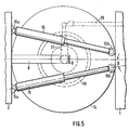
- the rolling movements of the secondary carriage 1 in relation to the primary carriage 2 which then occur when driving straight ahead can be absorbed in a simple manner via two steering shock absorbers 15, the arrangement of which in the region of the turntable 14 is also shown schematically in FIG. 5.
- They can be arranged, for example, above the articulated brake 11 in such a way that they are supported at one end 15a on a carriage, for example 2, and with the other end 15b on the carriage 1.
- the shock absorbers 15 can be arranged in such a way that they are r. it the connecting axis of the two carriage halves 1 and 2 form an angle ⁇ .
- the damper functions are then increasingly taken over by the articulated brake 11. It is also advantageous if a partial brake pressure is generated in the articulated brake 11 at high driving speeds, which is used for stabilization when driving straight ahead.
- control can be carried out via the switch 18 in such a way that the service brake 21 is also acted on at the same time. This makes it impossible for this maximum articulation angle ⁇ to be exceeded, as a result of which the body of both the primary and the secondary car would be damaged.
- the articulated brake significantly increases the ability of articulated vehicles to corner, even on wet and slippery roads.
- an articulated brake operating according to the invention can also be advantageously used in the joints of other vehicles which are connected to one another via an articulation. If the articulated brake is applied via the service brake, the secondary carriage can be effectively prevented from breaking out in relation to the primary carriage, both when driving straight ahead and when cornering.
Landscapes
- Engineering & Computer Science (AREA)
- Chemical & Material Sciences (AREA)
- Combustion & Propulsion (AREA)
- Transportation (AREA)
- Mechanical Engineering (AREA)
- Vehicle Body Suspensions (AREA)
- Steering-Linkage Mechanisms And Four-Wheel Steering (AREA)
- Body Structure For Vehicles (AREA)
- Air-Conditioning For Vehicles (AREA)
- Steering Control In Accordance With Driving Conditions (AREA)
- Arrangement Or Mounting Of Propulsion Units For Vehicles (AREA)
Abstract
Description
Die Erfindung betrifft ein Gelenkfahrzeug mit mehreren Achsen, insbesondere einen Gelenkomnibus, der einen Primär- und Sekundärwagen aufweist, bei dem über einen insbesondere den Sekundärwagen zugeordneten Antriebsmotor zumindest die Achse des Sekundärwagens angetrieben ist und bei dem der Sekundärwagen über eine Gelenkverbindung mit dem Primärwagen verbunden ist, wobei zur Lenkung des Fahrzeuges insbesondere die Vorderachse des Primärwagens vorgesehen ist.The invention relates to an articulated vehicle with a plurality of axles, in particular an articulated bus, which has a primary and secondary car, in which at least the axis of the secondary car is driven via a drive motor, in particular associated with the secondary car, and in which the secondary car is connected to the primary car via an articulated connection , in particular the front axle of the primary car being provided for steering the vehicle.
Solche Gelenkfahrzeuge sind als Gelenkomnibusse bekannt. Dabei ist zwischen dem Primärwagen und dem Sekundärwagen ein Drehkranz angeordnet, der den Schwenkpunkt des Sekundärwagens zum Primärwagen bildet, wobei in diesem Bereich die Fahrzeugkarosserien seitlich von Faltenbälgen ersetzt sind. Bei Kurvenfahrten sind solche Fahrzeuge insbesondere dadurch problematisch, daß der Sekundärwagen mit dem Primärwagen einen Knickwinkel bildet und daher die Schubkräfte des Sekundärwagens je nach Knickwinkel unterschiedlich auf den Primärwagen entlang einer Tangente, die an den von der zu fahrenden Kurve gebildeten Kreis zu denken ist, wirken. Das würde ohne besondere Abstützung zwischen Primär- und Sekundärwagen dazu führen, daß der Primärwagen in seiner Kurvenlage stark beeinträchtigt wird. Deshalb ist es bekannt (DE-OS 27 48 713) den Knickwinkel für ein Gelenkfahrzeug dadurch zu beeinflussen, daß zwischen dem Primär- und dem Sekundärwagen Zylinder angeordnet sind, die in Richtung auf die Strecklage des Gelenkzuges vorgespannt sind. Mit solchen Dämpferzylindern läßt sich ein ungehindertes Einknicken des Sekundärwagens gegenüber dem Primärwagen über einen bestimmten Bereich verhindern, da diese Zylinder wegen der ihnen aufgeprägten Vorspannung stabilisierend und insbesondere bei schnellen, größeren Einknickbewegungen entgegen den dabei auftretenden Kräften wirken. Durch eine solche hydraulische Regelung können aber Blockierkräfte auf das Fahrgestell und den Aufbau wirken, da die Dämpfer im wesentlichen in derselben Richtung wie die Schubkräfte wirken und daher im Falle ihrer Beaufschlagung die vollen Schubkräfte kompensieren müssen. Hierdurch bleibt es unvermeidlich, daß die mit dem Fahrgestell verbundenen Dämpfer die Kräfte auch auf dieses und damit auch auf den Aufbau übertragen. Solche Dämpfer können auch nicht verhindern, daß der Sekundärwagen gegenüber dem Primärwagen bei starker Kurvenfahrt Schlingerbewegungen ausführt.Articulated vehicles of this type are known as articulated buses. In this case, a slewing ring is arranged between the primary carriage and the secondary carriage, which forms the pivot point of the secondary carriage to the primary carriage, the vehicle bodies being replaced laterally by bellows in this area. When cornering, such vehicles are particularly problematic in that the secondary car forms an articulation angle with the primary car and therefore the thrust forces of the secondary car, depending on the articulation angle, act differently on the primary car along a tangent that is to be thought of as the circle formed by the curve to be driven . Without special support between the primary and secondary cars, this would result in the primary car being severely impaired in its cornering position. Therefore it is known (DE-OS 27 48 713) to influence the articulation angle for an articulated vehicle in that cylinders are arranged between the primary and the secondary car, which are biased towards the extended position of the articulated cable. With such damper cylinders, an unimpeded buckling of the secondary carriage relative to the primary carriage can be prevented over a certain area, since these cylinders have a stabilizing effect against the forces occurring due to the preload impressed on them, and in particular with rapid, larger buckling movements. Such a hydraulic control can, however, have blocking forces acting on the chassis and the body, since the dampers act essentially in the same direction as the thrust forces and therefore have to compensate for the full thrust forces when applied. As a result, it remains inevitable that the dampers connected to the chassis also transmit the forces to the chassis and thus to the body. Such dampers also cannot prevent the secondary car from making wobbling movements when cornering heavily when cornering.
Der Erfindung liegt die Aufgabe zugrunde, ein Gelenkfahrzeug, insbesondere einen Gelenkomnibus so zu gestalten, -― daß es auch auf nasser oder glatter Fahrbahn selbst bei starker Kurvenlage sicher gesteuert werden kann, ohne daß ein Ausbrechen des Fahrzeuges oder ein Abknicken zwischen dem Sekundär- und dem Primärwagen befürchtet zu werden braucht.The invention has for its object to design an articulated vehicle, in particular an articulated bus so that it can be safely controlled even on wet or slippery road surfaces, even when cornering heavily, without the vehicle breaking out or kinking between the secondary and the primary car needs to be feared.
Die Erfindung besteht darin, daß eine Gelenkbremse vorgesehen ist, die in Abhängigkeit des Knickwinkels zwischen Primär- und Sekundärwagen auf die Gelenkverbindung wirkt. Mit einer solchen Gelenkbremse kann erreicht werden, daß je nach Knickwinkel eine weitere Drehbewegung des Gelenkes zu größeren Winkeln hin erschwert wird. Beim maximalen, vorher bestimmbaren Knickwinkel kann die Gelenkbremse ihre maximale Bremskraft entfalten, so daß eine weitere Vergrößerung des Knickwinkels nicht mehr eintreten kann. Bei Geradeausfahrt, also wenn sowohl der Sekundär- als auch der Primärwagen entlang der Achse gesteuert werden, wird die Gelenkbremse wirkungslos und steigert ihre Bremskraft in dem Maße, indem der Knickwinkel durch eine Kur- venfahrt vergrößert wird. Dabei können die Bremskräfte senkrecht zur Schubrichtung des Sekundärwagens auf den Primärwagen nur zwischen geeignet am Gelenk vorgesehenen Flächen wirken. Hierzu werden nur wesentlich kleinere Bremskräfte benötigt.The invention consists in that an articulated brake is provided which acts on the articulated connection as a function of the articulation angle between the primary and secondary car. With such an articulated brake it can be achieved that, depending on the articulation angle, a further rotational movement of the articulation toward larger angles is made more difficult. At the maximum, The articulated brake can develop its maximum braking force so that the articulation angle can be determined beforehand, so that a further increase in the articulation angle can no longer occur. When driving straight ahead, that is if both of the secondary can be controlled as well as the primary carriage along the axis, the articulated brake is inefficient and increases its braking force to the extent by the bend angle is increased by a venfahrt originally K. The braking forces perpendicular to the direction of thrust of the secondary carriage can only act on the primary carriage between surfaces suitably provided on the joint. Only significantly smaller braking forces are required for this.
Die Gelenkbremse kann z.B. eine druckluftbetätigte Rei- bungsbremse sein. Solche Gelenkfahrzeuge sind üblicherweise mit Druckluftaggregaten ausgestattet, die daher auch, ohne daß eine zusätzliche Hilfsenergieversorgung an einem Fahrzeug mit der erfindungsgemäßen Gelenkbremse vorgesehen zu sein braucht, zum Betätigen der Gelenkbremse eingesetzt werden können. Eine Reibungsbremse kann im Bereich der Verbindung der beiden Wagenhälften wirkungsvoll angeordnet werden und so wirken, daß sie bei dem größten zugelassenen Knickwinkel eine weitere Vergrößerung dieses Winkels verhindern kann. Die Bremse kann natürlich auch eine öldruckbetätigte Scheibenbremse sein.The joint brake can be for example a pneumatically operated R egg environment brake. Articulated vehicles of this type are usually equipped with compressed air units, which can therefore also be used to actuate the articulated brake without the need to provide an additional auxiliary power supply to a vehicle with the articulated brake according to the invention. A friction brake can be effectively arranged in the area of the connection between the two car halves and act in such a way that it can prevent a further increase in this angle at the largest permitted articulation angle. The brake can of course also be an oil pressure-actuated disc brake.
Um die Bremswirkung in Abhängigkeit von dem Knickwinkel steuern zu können, ist es günstig, wenn z.B. im Bereich des Drehkranzes ein mechanischer Stufenschalter vorgesehen ist, der aus einem Stufenrad besteht, das seinen Umfang stufenförmig vergrößert und mit mechanischen Schaltpunkten dann in Berührung kommt, wenn der entsprechende Knickwinkel erreicht ist. Dabei können die Schaltpunkte bei einer Beaufschlagung durch das Stufenrad die Druckluftzufuhr zur Reibungsbremse über Magnetventile steuern. Eine solche Stufenschaltung wird in den meisten Fällen ausreichen, die Bremswirkung innerhalb der durch den Stufenschalter definierten Winkelbereicle konstant auftreten zu lassen. Es kann aber auch günstig sein, einen stufenlosen Schalter vorzusehen, der die winkelabhängige Regelung ermöglicht. Dies kann z.B. mit Hilfe einer elektrischen Regelung von Ventilen vorgenommen werden, wobei dabei der Abgriff winkelabhängig über Potentiometer erfolgen kann. Diese Ausgestaltung eröffnet auch die Möglichkeit, andere Steuervorgänge auszulösen. So ist es z.B. möglich, bei Erreichen des maximalen Knickwinkels ein Warnsignal für den Fahrer auszulösen oder z.B. bei Automatikgetrieben und Rückwärtsfahrt, wo der maximale Knickwinkel erreicht werden kann, den Rückwärtsgang selbsttätig in den-Leerlauf umzuschalten. Eine überbelastung des Fahrgestelles wird so vermieden.In order to be able to control the braking effect as a function of the articulation angle, it is advantageous if, for example, a mechanical step switch is provided in the area of the slewing ring, which consists of a step wheel that increases its circumference in steps and comes into contact with mechanical switching points when the appropriate kink angle is reached. The switching points can control the compressed air supply to the friction brake via solenoid valves when acted on by the stepped wheel. In most cases, such a tap change will suffice to allow the braking effect to occur constantly within the angle range defined by the tap changer. It can also be inexpensive to provide a stepless switch that enables angle-dependent control. This can be done, for example, with the aid of an electrical control of valves, with the tap being able to be tapped depending on the angle using potentiometers. This configuration also opens up the possibility of triggering other control processes. For example, it is possible to trigger a warning signal for the driver when the maximum articulation angle is reached or, for automatic transmissions and reverse driving, where the maximum articulation angle can be reached, to automatically switch the reverse gear into neutral. This avoids overloading the chassis.
Sehr vorteilhaft ist es, wenn die Gelenkbremse bei Betätigung der Betriebsbremse beaufschlagt wird. Dadurch kann vermieden werden, daß bei einem starken Abbremsen der Sekundärwagen gegenüber dem Primärwagen ausbricht. Er wird insbesondere durch eine volle Beaufschlagung der Gelenkbremse in seiner Lage gegenüber dem Primärwagen fixiert. Schlingerbewegungen oder eine seitliche Versetzung können dann nicht mehr auftreten.It is very advantageous if the articulated brake is applied when the service brake is actuated. This can prevent the secondary car from breaking out compared to the primary car when the brakes are applied hard. In particular, it is fixed in its position in relation to the primary carriage by fully applying the articulated brake. Rolling movements or a lateral displacement can then no longer occur.
Weiterhin ist es günstig, wenn beim Erreichen des maximalen Knickwinkels sowohl die Betriebs- als auch die Gelenkbremse über die Schalter beaufschlagt werden. Das hat zur Folge, daß kein größerer als der maximale Knickwinkel auftreten kann, da das Fahrzeug in diesem Falle sofort abgebremst wird. Beschädigungen, bei beim Überschreiten dieses Winkels an der Karosserie sowohl des Primär- aus auch des Sekundärwagens hervorgerufen werden würden, können hierdurch wirkungsvoll vermieden werden.Furthermore, it is advantageous if, when the maximum articulation angle is reached, both the service brake and the articulated brake are applied via the switches. The result of this is that no greater than the maximum articulation angle can occur, since the vehicle is braked immediately in this case. Damage that would be caused to the body of both the primary and the secondary car when this angle is exceeded can be effectively avoided in this way.
Zusätzlich zu der die Änderung des Knickwinkels hemmenden Bremswirkung können in günstiger Weise noch Lenkstoßdämpfer zwischen dem Primär- und dem Sekundärfahrzeug vorgesehen sein, die sich jeweils an den gegenüberliegenden Fahrzeugseiten abstützen und in einem Winkel zur Längsachse des Fahrzeuges angeordnet sein können. Diese Lenkstoßdämpfer haben den Vorteil, daß sie eine Schlingerbewegung des Sekundärwagens in Geradeausfahrt dämpfen können. Gleichzeitig kann dadurch die Gelenkbremse so gesteuert werden, daß sie bei kleinen auftretenden Knickwinkeln, wie sie z..B. durch Schlingerbewegungen hervorgerufen werden, nicht anspricht. Man könnte diese Steuerung in Geradeausfahrt auch über eine entsprechende Steuerung der erfindungsgemäßen Gelenkbremse vornehmen, dazu wäre aber eine umfangreichere Regelung notwendig. Eine Lösung'mit den Lenkstoßdämpfern ist aber für die kleinen Knickwinkel vollkommen ausreichend und stellt die einfachere Möglichkeit dar. Die Lenkstoßdämpfer können auch so ausgelegt werden, daß sie bei Überschreiten einer vorgegebenen Einknickgeschwindigkeit blockieren, so daß ein weiteres Abknicken von Primär- und Sekundärwagen vermieden wird.In addition to the braking effect which inhibits the change in the articulation angle, steering shock absorbers can also be provided in a favorable manner between the primary and the secondary vehicle, each of which is located on the opposite vehicle support sides and can be arranged at an angle to the longitudinal axis of the vehicle. These steering shock absorbers have the advantage that they can dampen a rolling movement of the secondary carriage when driving straight ahead. At the same time, the articulated brake can be controlled in such a way that it occurs at small articulation angles, such as, for example. caused by rolling movements, does not respond. This control could also be carried out while driving straight ahead by means of a corresponding control of the articulated brake according to the invention, but this would require a more extensive control. A solution with the steering shock absorbers is, however, completely sufficient for the small articulation angles and represents the simpler possibility. The steering shock absorbers can also be designed such that they block when a predetermined buckling speed is exceeded, so that a further kinking of primary and secondary cars is avoided .
Um die Kurvenlage noch sicherer zu machen, ist es günstig, wenn der Tank und/oder alle anderen schweren Zubaugeräte zwischen Hinterachse und dem Gelenk so nahe wie möglich am Gelenk angebracht sind. Dadurch kann die Auflagelast des Sekundärwagens im Gelenk größer sein. Schlingerbewegungen werden dadurch verhindert und machen die Verbindung zwischen den beiden Fahrzeugwagen sicherer.In order to make cornering even safer, it is advantageous if the tank and / or all other heavy attachments between the rear axle and the joint are attached as close as possible to the joint. As a result, the support load of the secondary carriage in the joint can be greater. This prevents lurching movements and makes the connection between the two vehicles more secure.
Die Erfindung eröffnet auch die Möglichkeit, die Gelenkbremse bei hohen Fahrgeschwindigkeiten mit einem Teilbremsdruck zu beaufschlagen, so daß auch die Geradeausfahrt stabilisiert ist.The invention also opens up the possibility of applying a partial brake pressure to the articulated brake at high driving speeds, so that straight-ahead driving is also stabilized.
Bei Gelenkomnibussen großer Länge ist es im Hinblick auf Einhaltung der gesetzlich vorgeschriebenen maximalen Kurvenradien zum Teil notwendig, neben der Lenkung einer Achse des Primärwagens auch die Achse oder die Achsen des Sekundärwagens zu lenken. Hier bietet die Ausgestaltung nach der Erfindung den Vorteil, daß die Gelenkbremse mit einem über einen Befestigungsarm fest mit dem Primärwagen verbundenen Achsbolzen versehen werden kann, der ohnehin für die Gelenkbremse benötigt wird, und daß dieser Achsbolzen auf der vom Befestigungsarm abgewandten Seite dazu ausgenutzt werden kann, um einen Betätigungsarm für die Lenkerstange zu den gelenkten Achsen des Sekundärwagens zu befestigen. Diese Ausführungsform läßt eine raumsparende Anordnung zu, bei der keine Schwierigkeiten für die Unterbringung der Gelenkbremse, der Stoßdämpfer und der Betätigung für die Zusatzlenkung am Sekundärwagen auftreten.In the case of articulated buses of long length, in order to comply with the legally prescribed maximum curve radii, it is sometimes necessary to steer the axle or the axles of the secondary car in addition to steering an axle of the primary car. Here, the design according to the invention has the advantage that the articulated brake can be provided with an axle bolt fixedly connected to the primary carriage via a fastening arm, which is anyway required for the articulated brake, and that this axle bolt on the side facing away from the fastening arm can be used to provide an actuating arm for the handlebar to the steered axles of the secondary carriage to fix. This embodiment allows a space-saving arrangement in which there are no difficulties for the accommodation of the articulated brake, the shock absorber and the actuation for the additional steering on the secondary carriage.
Die Merkmale der Erfindung sollen anhand der in den Figuren beispielsweise gezeigten schematischen Darstellungen im folgenden näher erläutert werden. Es zeigt
- Figur 1 eine schematische Darstellung eines mehrachsigen Gelenkomnibusses in Geradeausfahrt, Figur 2 eine schematische Darstellung eines mehrachsigen Gelenkomnibusses in Kurvenfahrt,
Figur 3 eine schematische Darstellung einer erfindungsgemäß angeordneten Gelenkbremse, Figur 4 eine schematische Darstellung eines Steuerschalters undFigur 5 eine schematische Darstellung der Gelenkverbindung mit Lenkstoßdämpfern.
- 1 shows a schematic illustration of a multi-axle articulated bus in straight-ahead driving, FIG. 2 shows a schematic illustration of a multi-axle articulated bus in cornering, FIG. 3 shows a schematic illustration of an articulated brake arranged according to the invention, FIG. 4 shows a schematic illustration of a control switch and FIG.
In der Fig. 1 ist ein Gelenkomnibus dargestellt, bei welchem mit 1 ein Sekundärwagen bezeichnet ist und mit 2 ein Primärwagen, die über eine Gelenkverbindung 3 miteinander in Verbindung stehen. In dem gezeigten Beispiel trägt der Sekundärwagen 1 das Antriebsaggregat 6 und kann vom Primärwagen aus über die lenkbare Achse 5 gesteuert werden. Die beiden Wagen sind über Faltenbälge im Bereich der Gelenkverbindung seitlich miteinander verbunden, wie dies bei Gelenkomnibussen z.B. der Fall ist. Weiterhin ist ein solcher Gelenkzug üblicherweise mit einer Betriebsbremse 21 ausgestattet, die in der Fig. 1 nur schematisch für die Achse 5a gezeigt ist. Es ist vorgesehen, daß eine solche Betriebsbremse 21 mit der im Bereich der Gelenkverbindung 3 angeordneten Gelenkbremse 11 so zusammenwirkt, daß diese voll beaufschlagt wird, wenn die Betriebsbremse 21 betätigt wird. Es ist auch möglich, das Antriebsaggregat als Mittelmotor 6' zum Antrieb der Achse 5a vorzusehen. Die Belastung im Bereich der Gelenkverbindung 3 wird aber bei Anordnung des Antriebsaggregates 6 im Sekundärwagen geringer.1 shows an articulated bus, in which 1 denotes a secondary car and 2 a primary car, which are connected to one another via an articulated
In der Fig. 2 ist ein solches Gelenkfahrzeug in Kurvenfahrt schematisch dargestellt. Dabei bilden der Sekundärwagen 1 und der Primärwagen 2 einen Knickwinkel 0( miteinander, der in Abhängigkeit des Lenkausschlages der Steuerräder 5 sich einstellt. In dieser Fahrtstellung treten am Primärwagen 2 Schubkräfte auf, die vom Sekundärwagen 1 herrühren und entsprechend einem Kräfteparallelogramm nicht vollständig in Richtung der Längsachse des Primärwagens 2 wirken. Diese Tatsache ist für die problematische Kurvenlage solcher Gelenkfahrzeuge verantwortlich und kann dazu führen, daß auf nasser oder glatter Fahrbahn der Sekundärwagen gegenüber dem Primärwagen abknickt. Um dies zu verhindern, sind bei bekannten Bauarten zwischen den sich gegenüberliegenden Enden 1a und 2a der beiden Wagen Stoßdämpfer so angebracht, daß sie entlang der auftretenden Kraftkomponenten wirken. Dadurch müssen von solchen Stoßdämpfern die vollen Schubkräfte aufgenommen werden, die dann auf das Fahrgestell und auf den Aufbau weitergeleitet werden, wodurch diese Teile sehr beansprucht werden.Such an articulated vehicle is shown schematically in cornering in FIG. 2. The secondary carriage 1 and the primary carriage 2 form an articulation angle 0 (with one another, which is established as a function of the steering deflection of the
Um dies zu verhindern, ist es erfindungsgemäß vorgesehen, in der Gelenkverbindung 3 eine Gelenkbremse 11 vorzusehen, die in Fig. 1 und 2 angedeutet und schematisch dargestellt aus der Fig. 3 zu ersehen ist und z.B. in der Art einer druckmittelbetätigten Scheiben- oder Lamellenbremse ausgebildet ist. Die Gelenkverbindung wird dabei zwischen den beiden sich gegenüberliegenden Enden 1a und 2a der beiden Wagen 1 und 2 so hergestellt, daß ein Befestigungsarm 8, der an dem Primärwagen 2 befestigt ist, mit einem Achsbolzen 9 drehfest verbunden ist, an welchem Bremsscheiben 9a und 9b vorgesehen sein können. Diese Bremsschreiben können mit an einem Bremsgehäuse 10 vorgesehenen Bremsflächen 10a und 10b zusammenwirken, wobei das Bremsgehäuse 10 und die Bremsflächen 10a und 10b fest mit dem anderen Wagen, hier also mit dem Sekundärwagen 1, in Verbindung stehen. Die Gelenkbremse kann z.B. eine druckluftbetätigte Reibungsbremse sein, die über eine Druckluftleitung 17 von einem der beiden Wagen, der auch das sich üblicherweise an solchen Gelenkfahrzeugen befindende Druckluftaggregat trägt, in nicht näher dargestellter Weise beaufschlagt werden. Die dadurch hervorgerufenen Bremskräfte KB wirken mit einer solchen Gelenkbremse senkrecht zu den von einem Wagen auf den anderen übertragenen Schubkräften KS. Die Einhaltung eines bestimmten Knickwinkels kann von der Gelenkbremse 11 dann mit wesentlich geringeren Kräften besorgt werden, wobei die Gelenkbremse so angesteuert werden kann, daß sie eine immer größer werdende Bremskraft mit zunehmenden Knickwinkeln entfaltet. Die auftretenden Schubkräfte des Sekundärwagens 1 können somit keine Blockierkräfte mehr hervorrufen, die auf das Fahrgestell und den Aufbau negative Einflüsse haben könnten.In order to prevent this, it is provided according to the invention to provide an articulated
Wie in den Fig. 1 und 2 und in den Fig. 4 und 5 gestrichelt gezeigt ist, kann der Achsbolzen 9, der im Ausführungsbeispiel mit der Gelenkachse zusammenfällt, auch dazu ausgenützt werden, um die Zwangslenkung einer - oder mehrerer - Achse 7 des Sekundärwagens zu bewirken. Mit größer werdender Gesamtlänge des Gelenkomnibusses nämlich wird es im Hinblick auf die Einhaltung gewisser vorgeschriebener Kurvenradien notwendig, neben der Achse 5 des Primärwagens 2 auch die Achse 7 des Sekundärwagens 1 mitzulenken, was in üblicher Art über eine lenkbare Anordnung der Räder der Achse 7 und über eine diesen zugeordnete Spurstange 25 sowie eine zum Primärwagen 2 führende Lenkstange 26 geschieht. Die Lenkstange 26 kann nun in sehr einfacher Weise an einem Betätigungsarm 27 angelenkt sein, der drehfest mit dem Achsbolzen 9 verbunden ist. Da dieser Achsbolzen 9 fest mit dem Primärwagen 2 über den Befestigungsarm 8 in Verbindung steht, werden die Räder der Achse 7 bei Kurvenfahrt (Fig. 2) zwangsläufig mitgelenkt. Platzschwierigkeiten bei der Unterbringung der Anlenkung der Lenkstange 26 am Primärwagen treten nicht auf, obwohl im Bereich der Gelenkverbindung 3 die Gelenkbremse 11 und, wie noch erläutert werden wird, eine Steuereinrichtung für die Gelenkbremse 11 und Stoßdämpfer 15 angeordnet sind.As shown in FIGS. 1 and 2 and in FIGS. 4 and 5 in dashed lines, the axle pin 9, which coincides with the hinge axis in the exemplary embodiment, can also be used to force the steering of one - or more - axis 7 of the secondary carriage to effect. With increasing total length of the articulated bus, it becomes necessary with a view to complying with certain prescribed curve radii in addition to the
Aus den Fig. 4 und 5 geht hervor, daß der Achsbolzen 9 das Bremsgehäuse 10 möglichst abgedichtet nach oben durchdringt und an diesem, seinem von dem Befestigungsarm 8 abgewandten Ende fest mit dem Betätigungsarm 27 versehen ist, der einen Kugelgelenkzapfen 28 zur Anlenkung der Lenkstange 26 tragen kann.4 and 5 that the axle pin 9 penetrates the
Die Steuerung der Bremskraft in Abhängigkeit des Knickwinkels< läßt sich recht einfach über eine z.B. im Bereich eines das Gelenk zwischen Primärwagen 2 und Sekundärwagen 1 bildenden Drehkranzes 14 angeordnete und in Fig. 4 prinzi - piell gezeigten Stufenscheibe 12 erreichen, die fest mit einem der beiden Wagen, z.B. dem Primärwagen 2, über den fest an diesem angeordneten Achsbolzen 9 verbunden ist. Mit dieser Stufenscheibe können in einfacher Weise dann knickwinkelabhängig Schalter 18 betätigt werden, die sich auf einer Halterung 19, welche ihrerseits fest mit dem anderen Wagen, also in dem Fall dem Sekundärwagen 1, in nicht näher gezeigter Weise verbunden ist. Die von den Schaltern 18 ausgehenden Signale können dann auf bekannte Magnetventile 20 gegeben werden, die die Druckluftzufuhr über die Zufuhrleitung 17 in die Gelenkbremse 11 entsprechend regeln kann. Die Steuerung erfolgt dabei so, daß die Gelenkbremse in Geradeausfahrt wirkungslos wird und ihre Bremskraft mit größer werdenden Knickwinkeln erhöht, indem die Stufenscheibe durch die von der Drehbewegung in eine der Pfeilrichtungen hervorgerufene Schaltung der Schalter 18 eines und mit größer werdenden Winkeln mehrere Magnetventile 20 öffnet, so daß bei maximaler Bremskraft die Summe der über die einzelnen Ventile geleiteten Drucke in der Druckluftleitung 17 vorliegen und die Bremse beaufschlagen. Bei einem maximal vorgebbaren Knickwinkel kann die Gelenkbremse dann ihre maximale Bremskraft entfaltet haben, wodurch ein weiteres Abknicken und damit ein Vergrößern des Knickwinkels α zwischen den beiden Wagen 1 und 2 nicht mehr stattfinden kann. Dabei erfolgt dieses Blockieren so, daß der Sekundärwagen 1 sich nicht ..ehr mechanisch über in diesem Fall unter maximaler Spannung stehenden Stoßdämpfern am Primärwagen 2 abstützt, sondern eine weitere Drehbewegung im Gelenk 3 selbst verhindert wird.The control of the braking force as a function of the articulation angle <can be achieved quite simply via a stepped
Um die Steuerung einfacher zu machen, kann die Gelenkbremse in einem bestimmten, kleinen Winkelbereich ausgeschaltet bleiben. Die dann bei Geradeausfahrt auftretenden Schlingerbewegungen des Sekundärwagens 1 gegenüber dem Primärwagen 2 können in einfacher Weise über zwei Lenkstoßdämpfer-15 aufgefangen werden, deren Anordnung im Bereich des Drehkranzes 14 in Fig. 5 noch schematisch gezeigt ist. Sie können z.B. über der Gelenkbremse 11 so angeordnet sein, daß sie sich mit einem Ende 15a an einem Wagen, z.B. 2, abstützen und mit dem anderen Ende 15b am Wagen 1. Die Anordnung der Stoßdämpfer 15 kann dabei so erfolgen, daß sie r.it der Verbindungsachse der beiden Wagenhälften 1 und 2 einen Winkel β bilden. Mit größer werdendem Knickwinkel werden dann immer mehr die Dämpferfunktionen von der Gelenkbremse 11 übernommen. Es ist auch vorteilhaft, wenn bei hohen Fahrgeschwindigkeiten ein Teilbremsdruck in der Gelenkbremse 11 erzeugt wird, der zur Stabilisierung bei Geradeausfahrt entscheidend beiträgt.To make control easier, the articulated brake can remain switched off within a certain, small angular range. The rolling movements of the secondary carriage 1 in relation to the primary carriage 2 which then occur when driving straight ahead can be absorbed in a simple manner via two
Bei Erreichen des maximalen Knickwinkels kann die Steuerung über den Schalter 18 so ausgeführt werden, daß gleichzeitig auch die Betriebsbremse 21 mit beaufschlagt wird. Somit wird es unmöglich gemacht, daß dieser maximale Knickwinkel α überschritten wird, wodurch die Karosserie sowohl des Primär- als auch des Sekundärwagens beschädigt werden würde.When the maximum articulation angle is reached, control can be carried out via the
TEine Verbesserung der Kurvenlage kann noch dadurch erzielt werden, wenn der Tank 16, wie dies in Fig. 2 schematisch dargestellt ist, zwischen der Hinterachse des Sekundärwagens 1 und dem Gelenk 3 so nahe wie möglich am Gelenk 3 angebracht ist.An improvement in the cornering position can also be achieved if the
Durch die Gelenkbremse wird die Kurvenfahrttauglichkeit von Gelenkfahrzeugen auch auf nasser und glatter Fahrbahn erheblich erhöht. Selbstverständlich kann eine erfindungsgemäß arbeitende Gelenkbremse auch in Gelenken anderer Fahrzeuge, die miteinander über ein Gelenk in Verbindung stehen, vorteilhaft angewendet werden. Mit einer Beaufschlagung der Gelenkbremse über die Betriebsbremse kann weiterhin ein Ausbrechen des Sekundärwagens gegenüber dem Primärwagen sowohl in Geradeausfahrt als auch in Kurvenfahrt wirkungsvoll verhindert werden.The articulated brake significantly increases the ability of articulated vehicles to corner, even on wet and slippery roads. Of course, an articulated brake operating according to the invention can also be advantageously used in the joints of other vehicles which are connected to one another via an articulation. If the articulated brake is applied via the service brake, the secondary carriage can be effectively prevented from breaking out in relation to the primary carriage, both when driving straight ahead and when cornering.
Claims (14)
dadurch gekennzeichnet,
daß eine Gelenkbremse (11) vorgesehen ist, die in Abhängigkeit des Knickwinkels (α) zwischen Primär-(2) und Sekundärwagen (1) auf die Gelenkverbindung (3) wirkt.1. articulated vehicle with several axles, in particular articulated bus, which has a primary and a secondary car, in which at least the axis of the secondary car is driven via a drive motor, in particular, assigned to the secondary car, and in which the secondary car is connected to the primary car via an articulated connection, wherein in particular the front axle of the primary car is provided for steering the vehicle,
characterized,
that an articulated brake (11) is provided which acts as a function of the articulation angle (α) between the primary (2) and secondary car (1) on the articulation (3).
dadurch gekennzeichnet,
daß die Gelenkbremse eine druckmittelbetätigte. Reibungs- bremse (11) ist.2. articulated vehicle according to claim 1,
characterized,
that the articulated brake is operated by a pressure medium. R eibungs- brake (11).
dadurch gekennzeichnet,
daß zur knickwinkelabhängigen Steuerung Schalter (18) vorgesehen sind, die dem Primär- oder Sekundärwagen fest zugeordnet sind und von einer dem anderen Wagen zugeordneten Stufensteuerscheibe (12) betätigbar sind.3. Articulated vehicle according to claim 1 and 2, -
characterized,
that switches (18) are provided for articulation-dependent control, which are permanently assigned to the primary or secondary carriage and can be actuated by a stepped control disk (12) assigned to the other carriage.
dadurch gekennzeichnet,
daß die Gelenkbremse (11) bei Betätigung der Betriebsbremse beaufschlagt wird.4. articulated vehicle according to at least one of claims 1 to 3,
characterized,
that the articulated brake (11) is applied when the service brake is actuated.
dadurch gekennzeichnet,
daß bei Erreichen des maximalen Knickwinkels (cC) sowohl die Betriebs- (21) als auch die Gelenkbremse (11) über die Schalter (18) beaufschlagt werden.5. Articulated vehicle according to at least one of claims 1 to 4,
characterized,
that when the maximum articulation angle (cC) is reached, both the service brake (21) and the articulated brake (11) are applied via the switches (18).
dadurch gekennzeichnet,
daß die Druckluftzufuhr zur Gelenkbremse (11) über Magnetventile gesteuert wird, die von den Schaltern (18) betätigbar sind.6. articulated vehicle according to at least one of claims 1 to 4,
characterized,
that the compressed air supply to the articulated brake (11) is controlled via solenoid valves which can be actuated by the switches (18).
dadurch gekennzeichnet,
daß die winkelabhängige Regelung über Drosselventile erfolgt.7. Articulated vehicle according to claim 1 and 2,
characterized,
that the angle-dependent control takes place via throttle valves.
dadurch gekennzeichnet,
daß die winkelabhängige Regelung stufenlos elektrisch über Potentiometer erfolgt.8. articulated vehicle according to claim 1 and 2,
characterized,
that the angle-dependent regulation takes place continuously and electrically via potentiometers.
dadurch gekennzeichnet,
daß Lenkstoßdämpfer (15) zwischen Primär- (2) und Sekundärfahrzeug (1) vorgesehen sind, die sich jeweils an den gegenüberliegenden Fahrzeugseiten (1a, 2a) abstützen und unter einem Winkel (β) zur Längsachse des Fahrzeuges angeordnet sind.9. articulated vehicle according to at least one of claims 1 to 8,
characterized,
that steering shock absorbers (15) are provided between the primary (2) and secondary vehicle (1), which are each supported on the opposite vehicle sides (1a, 2a) and are arranged at an angle (β) to the longitudinal axis of the vehicle.
dadurch gekennzeichnet,
daß alle schweren Zubaugeräte, wie Kraftstofftank (16), Klimagerät, Heizung, Batterien o.dgl. zwischen Hinterachse (7) und Gelenk (3) am Sekundärwagen (1) angeordnet ist.10. articulated vehicle according to at least one of claims 1 to 9,
characterized,
that all heavy accessories, such as fuel tank (16), air conditioner, heating, batteries or the like. between the rear axle (7) and joint (3) on the secondary carriage (1) is arranged.
dadurch gekennzeichnet,
daß zur Fahrtstabilisierung bei hohen Geschwindigkeiten ein Teilbremsdruck in der Gelenkbremse erzeugt wird.11. Articulated vehicle according to one of claims 1 to 10,
characterized,
that a partial brake pressure is generated in the articulated brake for travel stabilization at high speeds.
dadurch gekennzeichnet,
daß die Gelenkbremse (11) mit einer über einen Befestigungsarm (8) fest mit dem Primärwagen (2) verbundenen Achsbolzen (9) versehen ist, der auf der vom Befestigungsarm (8) abgewandten Seite mit einem Betätigungsarm (27) für die Lenkstange zu der gelenkten Achse (7) versehen ist.12. Articulated vehicle according to claim 1 with a steered front axle on the primary carriage and at least one steered axle on the secondary carriage,
characterized,
that the articulated brake (11) is provided with an axle bolt (9) connected to the primary carriage (2) via an attachment arm (8), which on the side facing away from the attachment arm (8) has an actuating arm (27) for the handlebar to the steered axis (7) is provided.
dadurch gekennzeichnet,
daß der Achsbolzen (9) mit den Bremsscheiben (9a, 9b) versehen ist, mit einem Ende das Gehäuse (10) der Gelenkbremse (11) durchdringt und daß an diesem Ende der Betätigungsarm (27) befestigt ist.13. Articulated vehicle according to claim 12,
characterized,
that the axle pin (9) is provided with the brake discs (9a, 9b), with one end penetrates the housing (10) of the articulated brake (11) and that the actuating arm (27) is fastened to this end.
dadurch gekennzeichnet,
daß der Achsbolzen (9) abgedichtet das Gehäuse (10) der Gelenkbremse (11) durchdringt.14. Articulated vehicle according to claim 13,
characterized,
that the axle bolt (9) seals the housing (10) of the articulated brake (11) penetrates.
Priority Applications (1)
| Application Number | Priority Date | Filing Date | Title |
|---|---|---|---|
| AT81104302T ATE33801T1 (en) | 1980-08-23 | 1981-06-04 | ARTICULATED VEHICLE WITH MULTIPLE AXLES. |
Applications Claiming Priority (2)
| Application Number | Priority Date | Filing Date | Title |
|---|---|---|---|
| DE3031862 | 1980-08-23 | ||
| DE3031862A DE3031862C2 (en) | 1980-08-23 | 1980-08-23 | Articulated vehicle with several axles |
Publications (3)
| Publication Number | Publication Date |
|---|---|
| EP0046484A2 true EP0046484A2 (en) | 1982-03-03 |
| EP0046484A3 EP0046484A3 (en) | 1982-11-10 |
| EP0046484B1 EP0046484B1 (en) | 1988-04-27 |
Family
ID=6110262
Family Applications (1)
| Application Number | Title | Priority Date | Filing Date |
|---|---|---|---|
| EP81104302A Expired EP0046484B1 (en) | 1980-08-23 | 1981-06-04 | Multi-axle articulated vehicle |
Country Status (6)
| Country | Link |
|---|---|
| US (1) | US4469347A (en) |
| EP (1) | EP0046484B1 (en) |
| AT (1) | ATE33801T1 (en) |
| CA (1) | CA1164498A (en) |
| DE (2) | DE3031862C2 (en) |
| HU (1) | HU193631B (en) |
Cited By (6)
| Publication number | Priority date | Publication date | Assignee | Title |
|---|---|---|---|---|
| WO1984000730A1 (en) * | 1982-08-18 | 1984-03-01 | Falkenried Fahrzeug Gmbh | Method for adjusting the resistance to the lateral pivoting of road vehicles comprising at least two vehicle portions connected by an articulation unit, and articulation unit for implementing such method |
| EP0161472A3 (en) * | 1984-05-16 | 1987-08-26 | AUTOTRASPORTI PADOVA ATP S.p.A. | Device for controlling the relative angle between two parts of a semitrailer vehicle |
| US4763916A (en) * | 1984-02-24 | 1988-08-16 | Autoipari Kutato Es Fejleszto Vallalat | Hydraulic jackknifing-affecting apparatus for articulated vehicles |
| EP0381930A3 (en) * | 1989-02-07 | 1991-09-04 | MAURI & C. S.a.s. di MAURI Ambrogio e ZORLONI Costanza | Control unit for a rotatable platform for a three-axle articulated vehicle |
| EP0475340A1 (en) * | 1990-09-10 | 1992-03-18 | HYMER LEICHTMETALLBAU GmbH & Co. KG | Articulated connection for low floor articulated omnibus |
| EP2570335A3 (en) * | 2011-09-16 | 2018-10-17 | Samco Agricultural Manufacturing Limited | A trailer and a method and apparatus for coupling a trailer to a three-point linkage of a tractor |
Families Citing this family (17)
| Publication number | Priority date | Publication date | Assignee | Title |
|---|---|---|---|---|
| DE3623668A1 (en) * | 1986-07-12 | 1988-01-14 | Man Nutzfahrzeuge Gmbh | Kink protection brake for articulated bus |
| US5016899A (en) * | 1989-12-14 | 1991-05-21 | Leonard Euteneier | No-slack restricted-drum stabilizer for commercial multitrailer combinations |
| US5957476A (en) * | 1996-02-28 | 1999-09-28 | Simpson; William A. | Anti-jackknife system for tractor-trailers |
| AU770359B2 (en) | 1999-02-26 | 2004-02-19 | Shell Internationale Research Maatschappij B.V. | Liner hanger |
| FI117795B (en) * | 2001-12-21 | 2007-02-28 | John Deere Forestry Oy | Articulated vehicle stabilization |
| ATE325737T1 (en) * | 2003-11-15 | 2006-06-15 | Huebner Gmbh | TOWING VEHICLE WITH A PARTICULAR DOUBLE AXLE TRAILER |
| KR100892715B1 (en) | 2007-12-07 | 2009-04-15 | 현대자동차주식회사 | Large refractive bus lane control assistance system |
| HU229757B1 (en) * | 2011-11-02 | 2014-06-30 | Istvan Dr Szabo | Articulation with two pivoting poinisand carriage for vehicles |
| US9848954B2 (en) | 2013-12-20 | 2017-12-26 | Corbin E. Barnett | Surgical system and related methods |
| EP3227169B1 (en) | 2014-12-02 | 2020-08-12 | Husqvarna AB | All wheel drive robotic mower |
| CN105361983B (en) * | 2015-09-14 | 2017-05-10 | 张英华 | Robot and robot control method |
| US10040327B2 (en) * | 2016-05-10 | 2018-08-07 | Deere & Company | Oscillation control system and method |
| EP3484265A1 (en) | 2016-07-12 | 2019-05-22 | Husqvarna AB | All wheel drive robotic vehicle with steering brake |
| DE102017003148A1 (en) * | 2017-03-31 | 2018-10-04 | Scania Cv Ab | Method and system for controlling an articulated vehicle |
| DE102019127269A1 (en) * | 2019-10-10 | 2021-04-15 | Schaeffler Technologies AG & Co. KG | Articulated vehicle and method for safe steering and tracking of an articulated vehicle |
| US11548573B1 (en) * | 2021-08-20 | 2023-01-10 | David M Regen | Jackknife prevention apparatus |
| JP7758611B2 (en) * | 2022-03-23 | 2025-10-22 | 株式会社ジェイテクト | Control device for connected vehicles |
Family Cites Families (19)
| Publication number | Priority date | Publication date | Assignee | Title |
|---|---|---|---|---|
| US2201353A (en) * | 1938-03-19 | 1940-05-21 | Harold A Soulis | Motor vehicle construction |
| US2213221A (en) * | 1939-07-26 | 1940-09-03 | Clarence B Johnson | Fifth-wheel mechanism |
| DE847256C (en) * | 1950-08-03 | 1952-08-21 | Erhard Huebner | Roll brake for truck trailers |
| US3093713A (en) * | 1959-11-06 | 1963-06-11 | Grigsby Company Inc | Electrical component assembly |
| US3005643A (en) * | 1960-11-04 | 1961-10-24 | Frank C Dugan | Braking system for truck trailers |
| GB1075802A (en) * | 1963-08-29 | 1967-07-12 | Frederick John Charles Hope | Anti jack-knife device for use with fifth-wheel couplings particularly on articulated vehicles |
| GB1240554A (en) * | 1967-07-20 | 1971-07-28 | Isuzu Motors Ltd | Tractor-trailer combinations comprising anti-jack-knife devices |
| US3512803A (en) * | 1967-10-02 | 1970-05-19 | Mather Co | Stabilizing device for articulated vehicles |
| GB1307061A (en) * | 1969-01-31 | 1973-02-14 | Monnery D W | Articulated vehicle control system |
| US3580610A (en) * | 1969-05-06 | 1971-05-25 | Robert C Warren | Automatic antijackknifing control for articulated vehicles |
| US3819234A (en) * | 1972-03-06 | 1974-06-25 | Kelsey Hayes Co | Trailer sway control system |
| DE2420203C3 (en) * | 1974-04-26 | 1987-09-10 | Hamburger Hochbahn Ag, 2000 Hamburg | Device for protecting an articulated road vehicle against excessive buckling |
| HU173149B (en) * | 1975-07-14 | 1979-03-28 | Autoipari Kutato Intezet | Buckle hindering device for motor vehicle train |
| DE2547487A1 (en) * | 1975-10-23 | 1977-04-28 | Bosch Gmbh Robert | Steering control for rear drive articulated vehicle - with selective braking in response to bend angle and steering lock |
| DE2748713C2 (en) * | 1977-10-29 | 1986-11-27 | Daimler-Benz Ag, 7000 Stuttgart | Device for influencing the articulation angle for an articulated pull |
| DE2810651A1 (en) * | 1978-03-11 | 1979-09-13 | Maschf Augsburg Nuernberg Ag | TWO-PIECE OMNIBUS |
| DE2919831A1 (en) * | 1979-05-16 | 1980-11-20 | Maschf Augsburg Nuernberg Ag | Anti-jack-knife control for articulated vehicle - has trailer angle monitor and relative wheel speed control |
| US4313616A (en) * | 1979-05-18 | 1982-02-02 | Howard D U | Speed responsive trailer stabilizer with zero slack |
| HU179667B (en) * | 1979-12-28 | 1982-11-29 | Autoipari Kutato Intezet | Turn angle limiting device for jointed vehicle |
-
1980
- 1980-08-23 DE DE3031862A patent/DE3031862C2/en not_active Expired
-
1981
- 1981-06-04 EP EP81104302A patent/EP0046484B1/en not_active Expired
- 1981-06-04 DE DE8181104302T patent/DE3176720D1/en not_active Expired
- 1981-06-04 AT AT81104302T patent/ATE33801T1/en not_active IP Right Cessation
- 1981-08-18 US US06/294,060 patent/US4469347A/en not_active Expired - Fee Related
- 1981-08-18 HU HU812422A patent/HU193631B/en unknown
- 1981-08-19 CA CA000384161A patent/CA1164498A/en not_active Expired
Cited By (7)
| Publication number | Priority date | Publication date | Assignee | Title |
|---|---|---|---|---|
| WO1984000730A1 (en) * | 1982-08-18 | 1984-03-01 | Falkenried Fahrzeug Gmbh | Method for adjusting the resistance to the lateral pivoting of road vehicles comprising at least two vehicle portions connected by an articulation unit, and articulation unit for implementing such method |
| US4688818A (en) * | 1982-08-18 | 1987-08-25 | Juergen Grassmuck | Method for regulating the bending stability of road vehicles |
| US4763916A (en) * | 1984-02-24 | 1988-08-16 | Autoipari Kutato Es Fejleszto Vallalat | Hydraulic jackknifing-affecting apparatus for articulated vehicles |
| EP0161472A3 (en) * | 1984-05-16 | 1987-08-26 | AUTOTRASPORTI PADOVA ATP S.p.A. | Device for controlling the relative angle between two parts of a semitrailer vehicle |
| EP0381930A3 (en) * | 1989-02-07 | 1991-09-04 | MAURI & C. S.a.s. di MAURI Ambrogio e ZORLONI Costanza | Control unit for a rotatable platform for a three-axle articulated vehicle |
| EP0475340A1 (en) * | 1990-09-10 | 1992-03-18 | HYMER LEICHTMETALLBAU GmbH & Co. KG | Articulated connection for low floor articulated omnibus |
| EP2570335A3 (en) * | 2011-09-16 | 2018-10-17 | Samco Agricultural Manufacturing Limited | A trailer and a method and apparatus for coupling a trailer to a three-point linkage of a tractor |
Also Published As
| Publication number | Publication date |
|---|---|
| EP0046484A3 (en) | 1982-11-10 |
| HU193631B (en) | 1987-11-30 |
| ATE33801T1 (en) | 1988-05-15 |
| DE3031862A1 (en) | 1982-03-04 |
| EP0046484B1 (en) | 1988-04-27 |
| DE3031862C2 (en) | 1983-11-03 |
| CA1164498A (en) | 1984-03-27 |
| DE3176720D1 (en) | 1988-06-01 |
| US4469347A (en) | 1984-09-04 |
Similar Documents
| Publication | Publication Date | Title |
|---|---|---|
| EP0046484B1 (en) | Multi-axle articulated vehicle | |
| DE3342355C2 (en) | ||
| EP0141093B1 (en) | Suspension for steerable front wheels of motor vehicles | |
| DE3926665C2 (en) | Wheel suspension for motor vehicles | |
| DE3507141C2 (en) | ||
| WO2007118629A1 (en) | Steering knuckle for a vehicle | |
| DD203706A5 (en) | STABILIZATION DEVICE FOR VEHICLE AXLES | |
| DE3441560C2 (en) | ||
| DE3514823A1 (en) | INDEPENDENT WHEEL SUSPENSION FOR MOTOR VEHICLES | |
| DE3744089C1 (en) | Motor vehicle steering | |
| EP1565370B1 (en) | Swivel bearing and a steering axle equipped therewith | |
| DE69310779T2 (en) | Rear wheel steering device | |
| DE69013517T2 (en) | FOUR-WHEEL STEERING SYSTEM. | |
| DE60004214T2 (en) | SELF-DRIVING AXLE | |
| EP4598758A1 (en) | Wheel suspension system for a vehicle wheel of a motor vehicle, and motor vehicle | |
| DE3912520B4 (en) | Rear axle for a motor vehicle | |
| CH670426A5 (en) | ||
| DE102022104584A1 (en) | Steering system and steerable axle for a motor vehicle | |
| DE4134501A1 (en) | Semi-trailer lorry - has steering axle with steering servo unit, with generated steering force limited by e.g. pressure limitation valve | |
| DD202121A5 (en) | DEVICE FOR INFLUENCING THE KNUCKLE ANKLE BY MEANS OF FRICTION BRAKES FOR A JOINT TRAIN | |
| DE2332387A1 (en) | Independent front wheel suspension - effective suspension spring length is altered by a screw link when wheels are steered | |
| DE102020123524B4 (en) | Wheel module for a motor vehicle | |
| DE2263506A1 (en) | CONTROL DEVICE FOR A TRAILED CAR | |
| EP2871114B1 (en) | Steering axle | |
| DD244316A5 (en) | ANCHORING SYSTEM FOR RIGID AXLES OF VEHICLES WITH STAIRR ON THE CHASSIS FIXED, VERTICALLY MOVABLE ANCHORAGES |
Legal Events
| Date | Code | Title | Description |
|---|---|---|---|
| PUAI | Public reference made under article 153(3) epc to a published international application that has entered the european phase |
Free format text: ORIGINAL CODE: 0009012 |
|
| AK | Designated contracting states |
Designated state(s): AT BE CH DE FR GB IT LI LU NL SE |
|
| PUAL | Search report despatched |
Free format text: ORIGINAL CODE: 0009013 |
|
| AK | Designated contracting states |
Designated state(s): AT BE CH DE FR GB IT LI LU NL SE |
|
| 17P | Request for examination filed |
Effective date: 19830413 |
|
| RAP1 | Party data changed (applicant data changed or rights of an application transferred) |
Owner name: DIAMOIL S.A. |
|
| RAP1 | Party data changed (applicant data changed or rights of an application transferred) |
Owner name: SCHENK FAHRZEUGWERK GMBH |
|
| RAP1 | Party data changed (applicant data changed or rights of an application transferred) |
Owner name: SCHENK FAHRZEUGWERK GMBH |
|
| RAP1 | Party data changed (applicant data changed or rights of an application transferred) |
Owner name: HYMER-LEICHTMETALLBAU |
|
| RAP1 | Party data changed (applicant data changed or rights of an application transferred) |
Owner name: HYMER-LEICHTMETALLBAU |
|
| GRAA | (expected) grant |
Free format text: ORIGINAL CODE: 0009210 |
|
| AK | Designated contracting states |
Kind code of ref document: B1 Designated state(s): AT BE CH DE FR GB IT LI LU NL SE |
|
| REF | Corresponds to: |
Ref document number: 33801 Country of ref document: AT Date of ref document: 19880515 Kind code of ref document: T |
|
| ITF | It: translation for a ep patent filed | ||
| REF | Corresponds to: |
Ref document number: 3176720 Country of ref document: DE Date of ref document: 19880601 |
|
| ET | Fr: translation filed | ||
| PG25 | Lapsed in a contracting state [announced via postgrant information from national office to epo] |
Ref country code: LU Free format text: LAPSE BECAUSE OF NON-PAYMENT OF DUE FEES Effective date: 19880630 |
|
| GBT | Gb: translation of ep patent filed (gb section 77(6)(a)/1977) | ||
| PLBE | No opposition filed within time limit |
Free format text: ORIGINAL CODE: 0009261 |
|
| STAA | Information on the status of an ep patent application or granted ep patent |
Free format text: STATUS: NO OPPOSITION FILED WITHIN TIME LIMIT |
|
| 26N | No opposition filed | ||
| PG25 | Lapsed in a contracting state [announced via postgrant information from national office to epo] |
Ref country code: SE Effective date: 19890605 |
|
| PG25 | Lapsed in a contracting state [announced via postgrant information from national office to epo] |
Ref country code: BE Effective date: 19890630 |
|
| BERE | Be: lapsed |
Owner name: HYMER-LEICHTMETALLBAU Effective date: 19890630 |
|
| PG25 | Lapsed in a contracting state [announced via postgrant information from national office to epo] |
Ref country code: NL Effective date: 19900101 |
|
| NLV4 | Nl: lapsed or anulled due to non-payment of the annual fee | ||
| PG25 | Lapsed in a contracting state [announced via postgrant information from national office to epo] |
Ref country code: FR Free format text: LAPSE BECAUSE OF NON-PAYMENT OF DUE FEES Effective date: 19900228 |
|
| REG | Reference to a national code |
Ref country code: FR Ref legal event code: ST |
|
| PGFP | Annual fee paid to national office [announced via postgrant information from national office to epo] |
Ref country code: GB Payment date: 19920616 Year of fee payment: 12 |
|
| PG25 | Lapsed in a contracting state [announced via postgrant information from national office to epo] |
Ref country code: GB Effective date: 19930604 |
|
| PGFP | Annual fee paid to national office [announced via postgrant information from national office to epo] |
Ref country code: AT Payment date: 19930618 Year of fee payment: 13 |
|
| ITTA | It: last paid annual fee | ||
| PGFP | Annual fee paid to national office [announced via postgrant information from national office to epo] |
Ref country code: CH Payment date: 19930827 Year of fee payment: 13 |
|
| GBPC | Gb: european patent ceased through non-payment of renewal fee |
Effective date: 19930604 |
|
| PG25 | Lapsed in a contracting state [announced via postgrant information from national office to epo] |
Ref country code: AT Effective date: 19940604 |
|
| PG25 | Lapsed in a contracting state [announced via postgrant information from national office to epo] |
Ref country code: LI Effective date: 19940630 Ref country code: CH Effective date: 19940630 |
|
| EUG | Se: european patent has lapsed |
Ref document number: 81104302.5 Effective date: 19900412 |
|
| REG | Reference to a national code |
Ref country code: CH Ref legal event code: PL |
|
| PGFP | Annual fee paid to national office [announced via postgrant information from national office to epo] |
Ref country code: DE Payment date: 19950704 Year of fee payment: 15 |
|
| PG25 | Lapsed in a contracting state [announced via postgrant information from national office to epo] |
Ref country code: DE Effective date: 19970301 |